Table of Contents
Quick Links
Table of Contents
Troubleshooting

Related Manuals for Honeywell ENCAL 3000


Summary of Contents for Honeywell ENCAL 3000
- Page 1 • GASCHROMATOGRAPH ENCAL 3000 HARDWARE MANUAL...
- Page 2 2018 Elster GmbH All rights reserved. Elster GmbH is part of the Honeywell Group and the manufacturer of the device described in the following. Use only documentation published by the manufacturer. The amendment or translation of this manual requires the written consent of the manufacturer.
-
Page 3: Table Of Contents
Processor Board installed ......................41 Interconnection Board ..........................41 Internal sample system ........................... 43 5.4.1 Double Block and Bleed Function ................... 44 5.4.2 Internal Sample Bypass ........................ 45 ......................45 ARDWARE NSTALLATION Installation specifications ........................46 EnCal 3000 Hardware Manual 73022344 o... - Page 4 Cable glands cables andwires ....................55 6.4.2 Making the electrical and signal connections ..............58 6.4.3 Connections on the EnCal 3000 Interconnection board Version 1.x ....60 6.4.4 Connections on the EnCal 3000 Interconnection board Version 2.x ....64 6.4.5 Electrical device test to verify correct installation ............
- Page 5 Nomenclature/Abbreviations......................117 12.2 Definitions and explanations ......................120 12.3 CERTIFICATE EC-Type Examination ..................... 125 12.4 DECLARATION OF CONFORMITY ENCAL 3000..............127 12.5 IECEx Certificate ENCAL 3000 ......................128 12.6 FM Certificate of Conformity ......................132 ......................135 EYWORDS AND FIGURES 13.1...
-
Page 6: About This Manual And Device Delivery
Encal3000 controller). Figure 1.1: Parts of the Gas quality measurement system The enCal 3000 is suitable for worldwide use. You should use a manual in your mother tongue or a language with which you are extremely familiar to ensure that you understand all the information. -
Page 7: How To Use This Manual
It contains the explosion-relevant information as well as a summary of relevant safety and warning notices. In addition to general expertise, it enables the enCal 3000 to be handled safely and efficiently. Compliance with all given information and instructions is a requirement for safe working practice and correct handling of the device. -
Page 8: Symbols
/ Prohibited action) Prohibited action means that you must not complete the action described unless the specified conditions and requirements are satisfied and you are qualified for this work. 73022344 o EnCal 3000 Hardware Manual... - Page 9 This symbol on the device designates the connection for the functional earth (FE). Device symbol Denotes tips and recommendations which are interesting and useful for a certain topic, but which have no bearing on safety. EnCal 3000 Hardware Manual 73022344 o...
-
Page 10: Device Delivery
The packages may only be stored in enclosed rooms. • Avoid mechanical impacts during storage. • The storage time with a battery is up to one year, 2 years if the battery is then • replaced. 73022344 o EnCal 3000 Hardware Manual... -
Page 11: Intended Use Of Device
CAUTION If the device is transported in cold weather or extreme temperature fluctuations have occurred, the EnCal 3000 must be returned to room temperature (temperature at the place of use) slowly to prevent damage caused by the formation of condensation. -
Page 12: Additional Technical Help And Repairs
TAC or our customer service department will be delighted to help. The contact details are provided at the start of this manual Training classes Honeywell holds technical training classes that are taught by process control systems experts. For more information about these classes, contact your Honeywell representative, or see http://www.automationcollege.com... -
Page 13: Safety Information And Warnings
Direct contact with hot or cold surfaces can cause heat and ice burns. Prevent this by using your personal protective equipment (for example, CAUTION wear gloves). EnCal 3000 Hardware Manual 73022344 o... -
Page 14: Information For Handling The Device
EN 60079-0 2012 EN 60079-1 2014 United States standards Class 3600 2011 Class 3615 2006 Class 3810 2005 ANSI/ISA 60079-0 2013 ANSI/UL 60079-1 2015 NEC: Detailed information on this certificate can be found in ANNEX 73022344 o EnCal 3000 Hardware Manual... - Page 15 ANSI: ANSI/ISA 60079-0 2013 ANSI/UL 60079-1 2015 Detailed information on this certificate can be found in ANNEX The device may only be installed and used in the potentially dangerous zones specified on it. CAUTION EnCal 3000 Hardware Manual 73022344 o...
- Page 16 TAC. When carrying out mechanical work (transport, assembly, etc.), use your personal protective equipment (safety footwear, gloves, etc.) to avoid CAUTION injury. Never lift weights which may jeopardize your health. 73022344 o EnCal 3000 Hardware Manual...
-
Page 17: Authorized (Hardware) Personnel
Assembly, electrical installation, commissioning and inspection and maintenance work (opening the housing) may only be carried out by ATTENTION trained personnel authorized by Honeywell. The appropriate personnel have the expertise set out in Annex A of EN IEC 60079-14 or has comparable expertise, including: General safety rules •... -
Page 18: Information And Warnings On The Device Housing
Figure 2.1: Warning and information labels on the device Information on the device must be noted and obeyed in all circumstances. You must have adequate language skills to understand their meaning. ATTENTION 73022344 o EnCal 3000 Hardware Manual... -
Page 19: Safety Information About Gases
The breather valve must not be sealed or blocked. It may only be replaced by personnel authorized by Honeywell. ATTENTION EnCal 3000 Hardware Manual... -
Page 20: Electrical Information Connecting With Earth And Emergency Stop
Honeywell cannot accept any responsibility for compliance with provisions and regulations unless the work was carried out by Honeywell. We recommend that you read through the appropriate regulations again before installation. Compliance with standards and directives on the following topics, in particular, is... - Page 21 Use cables or wires and cable entries suitable at least up to 70°C (158°F / 343 K) ambient temperature. ATTENTION Utilisez des câbles ou des fils et des entrées de câbles adaptés à une température ambiante d'au moins 70°C (158°F / 343 K). EnCal 3000 Hardware Manual 73022344 o...
- Page 22 Connecting the device only when the power supply is off ATTENTION Fuses and batteries may only be replaced by trained personnel authorized by Honeywell. Les fusibles et les batteries ne peuvent être remplacés que par du personnel qualifié et autorisé par Honeywell. CAUTION The installation must comply with the local standards which apply to electrical and explosion protection (e.g.
-
Page 23: Explosion Protection
These screw- in parts must be suitable for the IIC Zone and have explosion-protection certification. The enCal 3000 may only be connected using cable glands. These must comply with local explosion-protection regulations and be installed or replaced by authorized trained personnel. - Page 24 ATTENTION! ELECTROSTATIC DANGER! ELECTROSTATIC HAZARD Because of the potential electrostatic charging of the paint layer, the housing should only be cleaned by using a damp cloth to prevent lectrostatic charging, CAUTION since otherwise sparks are possible 73022344 o EnCal 3000 Hardware Manual...
-
Page 25: Functional Design Of Encal 3000
FUNCTIONAL DESIGN OF ENCAL 3000 Recommissioning must not be carried out in a potentially explosive gas atmosphere and before you switch on the device, ensure that all the gas connections are sealed and the earthing or protective conductor has been CAUTION installed correctly. -
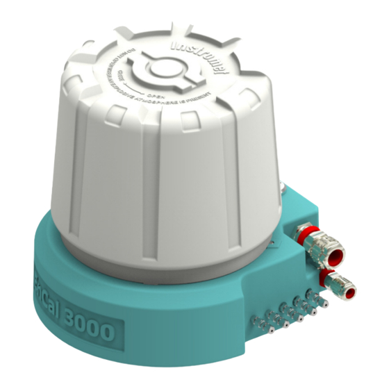
Page 26: Introduction /Enclosure/Hausing
FUNCTIONAL DESIGN OF ENCAL 3000 Introduction /Enclosure/Hausing The EnCal 3000 is an on-line gas chromatograph. The device is fully automatic and is enclosed in a tailor-made Ex-d housing which contains the electrical and analytical equipment. The explosion-proof aluminium housing essentially consists of a low base on to which a relatively high hood/cap is screwed using an M270 thread It can be positioned close to the sampling unit. -
Page 27: Most Important Features And Functions
FUNCTIONAL DESIGN OF ENCAL 3000 Most important features and functions Compact EX-d design allows for the harshest conditions imaginable in natural • gas applications installation clearance Ø 55 cm x 70 cm height, weight <30 kg • Complete stand-alone operation •... -
Page 28: Process Gas Chromatography - General Introduction
The concentration of each component is then measured at the end of the column by a detector. From the knowledge of the concentrations of each component, any property of the gas can be calculated. EnCal 3000 Hardware Manual 73022344 o... -
Page 29: Column
(for example type M5S mole sieve) Porous layer open tubular column: the stationary phase is a porous layer on • the inner wall of the column (for example type PPU) EnCal 3000 Hardware Manual 73022344 o... -
Page 30: Detector
TCDs newer design in MEMS technology (MEMS = Micro-Electro-Mechanical System), which are also used in the EnCal 3000 are much smaller in terms of volume. The components can be integrated at the same time much more accurately, so that the analytical precision is for example 1 ppm for n-pentane. -
Page 31: Sample Injector
This injector allows for a very precise control of the injection volume and temperature, on a remote base. Figure 4.4: MEMS Sample Injector EnCal 3000 Hardware Manual 73022344 o... -
Page 32: Result Findig And Presentation
The figure below shows examples of what chromatograms look like. Figure 4.5: Chromatograms All the main gas components can therefore be recorded directly and can undergo further processing. EnCal 3000 Hardware Manual 73022344 o... -
Page 33: Housing Interior With Major Internal Components
The following figure shows the exploded view of the different internal components of the Master Unit of the EnCal3000, the individual parts and variations are explained in detail with the functionalities of each component in the following paragraphs. EnCal 3000 Hardware Manual 73022344 o... -
Page 34: The Channel
The Channel A channel consists of the following subcomponents: Analytical Module: This is the heart of the EnCal 3000: it contains the column, sample • injector, detector and the heaters for the columns and the injector AMI (Analytical Module Interface): electronic circuit which controls the analytical •... - Page 35 Therefore, the retention times of the measured components would reduce always so that the separation of the measured components is deteriorated and a heating up of the column would be required after about 3 months. EnCal 3000 Hardware Manual 73022344 o...
- Page 36 For the carrier gas argon always an additional external humidity filter should be used. Figure 5.2: Overview of Channel Components The next page shows the internal gas flow configuration of the channels. EnCal 3000 Hardware Manual 73022344 o...
- Page 37 HOUSING INTERIOR WITH MAJOR INTERNAL COMPONENTS Figure 5.3: Internal Gas Flow Circuit for each Analytical Channel of the EnCal 3000, during Normal Operation (top) and sample Injection (below) EnCal 3000 Hardware Manual 73022344 o...
- Page 38 BF vent Pump sample valve Sample vent Sample Figure 5.4: Internal Gas Flow Circuit for each Analytical Channel with backflush of the EnCal 3000, before activating backflush valve (top) and after activating backflush valve (below) EnCal 3000 Hardware Manual 73022344 o...
-
Page 39: Processor Board
Data communication ports (COM1-4) for serial Modbus, Analogue and Digital I/O • USB Port • I/O Controller for Communication to the analytical channels • Pressure- and Temperature Sensor • Figure 5.5: Processor Board connections EnCal 3000 Hardware Manual 73022344 o... -
Page 40: Save Parameters In The Measuring Unit
The setting of the jumper, can be checked on the display of the “instrument status” page. See Section 3.2 of the software manual. How to set the jumper is shown in below. Figure 5.6: Save parameters in the measuring unit all bord versions EnCal 3000 Hardware Manual 73022344 o... -
Page 41: Processor Board Installed
HOUSING INTERIOR WITH MAJOR INTERNAL COMPONENTS 5.2.2 Processor Board installed When installed in the EnCal 3000, a flat cable makes the connection between the communication ports of the Processor Board and the Interconnection Board, which provides field connections (Phoenix connector) for the data communication signals. - Page 42 HOUSING INTERIOR WITH MAJOR INTERNAL COMPONENTS Figure 5.8: Interconnection Board in different variations The following diagram shows the overall electrical configuration EnCal3000 in a rough overview. Figure 5.9: Overall Electrical Configuration of the EnCal 3000 EnCal 3000 Hardware Manual 73022344 o...
-
Page 43: Internal Sample System
Helium the chance of internal damage is also reduced significantly. The purge and the small amount of helium that is vented into the housing also protects the internal components against moisture or other aggressive components entering the housing through the breather. EnCal 3000 Hardware Manual 73022344 o... -
Page 44: Double Block And Bleed Function
1 up to 5 pairs used for the streams. Depending on the configuration the manifold can support up to 3 or up to 6 streams (including the calibration gas stream). Unused positions on the manifold are blocked. EnCal 3000 Hardware Manual 73022344 o... -
Page 45: Internal Sample Bypass
The vent outputs from both modules return to the manifold and are combined to two venting outputs. 6 Hardware Installation All safety and warning notes in this document must be observed before further workis done CAUTION EnCal 3000 Hardware Manual 73022344 o... -
Page 46: Installation Specifications
(MV) must always be discharged separately. The power supply and the communication cables must be connected and installed as usual in industrial environments. The following diagram shows a typical system layout in simplified form: EnCal 3000 Hardware Manual 73022344 o... -
Page 47: Mechanical Installation (Assembly)
Do not carry out any unauthorized modifications or technical changes. If the product is modified or changed without authorization, its CE declaration will immediately become void. This may result in a safety risk! ATTENTION EnCal 3000 Hardware Manual 73022344 o... - Page 48 Select an installation height between 1.00 m and 1.50 m above the floor which is suitable for maintenance work. We recommend that you use larger gaps to make installation and maintenance work easier. The following sketch shows these requirements. Figure 6.2: Minimum installation gaps EnCal 3000 Hardware Manual 73022344 o...
-
Page 49: Device Dimensions
Figure 6.3: Side view with dimensions (without couplings and connections) Depending on local regulations, the weight of the EnCal 3000 (28kg) may exceed the allowable manual lifting limit for one person. -
Page 50: Place Of Use And Installation Site (Protection From Environmental Influences, Etc.)
Obey the explosion-protection rules at all times when working with tools or on items in hazardous zones CAUTION The EnCal 3000 must be installed as close as possible to the process gas sampling point to avoid having long supply lines and to ensure that you obtain current measurements. - Page 51 TAC. The measuring instrument weighs around 28 kg. Before installing it, ensure that the installation surface is strong enough to support it. The EnCal 3000 can be installed on a flat vertical surface (wall/measuring board) or on a horizontal surface.
-
Page 52: Assembly Hints
Prevent dirt and/or moisture getting into the device as it could possibly falsify the measurements or cause damage. Surfaces which come into contact with gas must be free of grease, oil, solvents and other impurities. EnCal 3000 Hardware Manual 73022344 o... -
Page 53: Electrical Installation
A functioning, effective lightning protection system must exist at the place of use to protect personnel, equipment and the device. CAUTION All input, output signals and power connections shall be of non- hazardous voltage and reinforced isolated from main CAUTION EnCal 3000 Hardware Manual 73022344 o... - Page 54 When connecting the earthing cable, ensure that it has a good, permanent, stable electrical contact. When making the contact and ATTENTION selecting the fastening materials, comply with the appropriate regulations, for example IEC/EN 60079-14. Figure 6.7: Example of earthing points on the device EnCal 3000 Hardware Manual 73022344 o...
-
Page 55: Cable Glands Cables Andwires
The device can also be fitted with bespoke cable glands, for example with ½" NPT threads, using adapters. Please contact your TAC for further details if you wish to change the standard equipment. Figure 6.8: Position of the cable end glands on the housing base EnCal 3000 Hardware Manual 73022344 o... - Page 56 18 inches. See below table for use of gland or conduit Approval Glands / Conduits Additional info ATEX Glands Use Barrier glands IECEx Glands Use Barrier glands NEC (US) Conduit seal within 18 inches (45 cm) EnCal 3000 Hardware Manual 73022344 o...
- Page 57 3000 and other devices. They should be selected on the basis of the requirements at the place of use. Honeywell generally recommends a signal cable with a conductor-to- conductor capacitance of less than 120 pF/m and an inductance of less than H/m.
-
Page 58: Making The Electrical And Signal Connections
It must be ensured that enclosure IP 66 is maintained and therefore the parts used must comply with this or a better (higher) rating. Openings which are not required must be fitted with appropriate blind plugs. EnCal 3000 Hardware Manual 73022344 o... - Page 59 Check that the connectors are secure when all the work has been ATTENTION completed. In addition to the wiring work, special parameterization may be required e.g. for Modbus communication. Detailed information is given in the software manual. EnCal 3000 Hardware Manual 73022344 o...
-
Page 60: Connections On The Encal 3000 Interconnection Board Version 1.X
HARDWARE INSTALLATION 6.4.3 Connections on the EnCal 3000 Interconnection board Version 1.x The drawing below shows the top lay-out of the Interconnection Board Version 1.x at the bottom of the unit. It contains all the connectors for external cables (marked with grey). - Page 61 LED (internal 12 V- circuit) LD102 LED (activation valves stream selection) LK 301-304 4 jumper for selection between RS232 and RS485 LK 305-307 jumper for selection of analogue input (4-20 mA or 0-10 V) EnCal 3000 Hardware Manual 73022344 o...
- Page 62 The Ethernet connection is used for connection with a PC or ModBus TCP/IP clients. It uses 4 wires, connected to connector J7. See picture below for location and wiring scheme. Figure 6.12: Location of Ethernet connector and wiring scheme EnCal 3000 Hardware Manual 73022344 o...
- Page 63 They are both independently configurable for RS232 or RS485 communication through link settings 301 to 304 (see pictures below for location, wiring scheme and link settings). Figure 6.13: Location of Serial ModBus connector (J6) Figure 6.14: Modbus Connection and Link settings EnCal 3000 Hardware Manual 73022344 o...
-
Page 64: Connections On The Encal 3000 Interconnection Board Version 2.X
HARDWARE INSTALLATION 6.4.4 Connections on the EnCal 3000 Interconnection board Version 2.x The drawing below shows the top lay-out of the Interconnection Board at the bottom of the unit. It contains all the connectors for external cables. For flame retardant wiring use cables according an ISO norm. - Page 65 LED 12V Supply for analytical modules and Vents LD3-6 LEDs Diagnostic of Analogue Outputs LD7-8 LEDs Diagnostic of internal Heating LK1-6 Jumper-Connections for RS232 and RS485 LK7-12 Jumper-Connections for data communication cable between IC-Board and processor board EnCal 3000 Hardware Manual 73022344 o...
- Page 66 The Ethernet connection is used for connection with a PC or ModBus TCP/IP clients. It uses 4 wires, connected to connector J7. See picture below for location and wiring scheme. Figure 6.17: Location of Ethernet connector (J7) and wiring scheme EnCal 3000 Hardware Manual 73022344 o...
- Page 67 HARDWARE INSTALLATION EnCal 3000 Hardware Manual 73022344 o...
- Page 68 RS485 communication through link settings LK1-3 and LK4-6 (see pictures below for location, wiring scheme and link settings). Figure 6.18: Location of Serial ModBus connector (J8) Figure 6.19: Modbus Connection and Link settings EnCal 3000 Hardware Manual 73022344 o...
-
Page 69: Electrical Device Test To Verify Correct Installation
Position the hood with the sealing ring and fully tighten the thread. Then ATTENTION turn the countersunk security screws upwards to the edge of the hood to prevent the hood being removed accidentally or through ignorance. EnCal 3000 Hardware Manual 73022344 o... -
Page 70: Fluidic Installation
The device has multiple gas connections for various functions. They are always fitted by the manufacturer. All gas and vent lines do have a 1/8” Swagelok connection to the EnCal 3000. On request also 3 mm connections are available. Figure 6.20: Fluidic connections... - Page 71 ) to a 1/16" pipe and connected to the internal sample gas system. This pipe is used as a flame arrester and must not be reduced in size. It must be more than 25 cm (19") in length and its maximum internal diameter may be 0.015". EnCal 3000 Hardware Manual 73022344 o...
- Page 72 HARDWARE INSTALLATION WARNING! DO NOT LOOSEN THE CONNECTORS FROM THE ENCAL 3000 HOUSING. THE SOLDERED TUBE WILL BE DAMAGED! THE JOINT BETWEEN CONNECTOR AND HOUSING IS AN INTEGRAL PART OF THE ENCAL 3000’s ATTENTION SAFETY APPROVAL To prevent loosening the connectors use a second key wrench to prevent the coupling from turning.
- Page 73 Use only tight, clean stainless steel gas pipes. Prevent dirt and/or moisture getting into the device as it could possibly falsify the measurements or cause damage. Controls and pipe couplings with low dead spaces are to be given preference. EnCal 3000 Hardware Manual 73022344 o...
- Page 74 Prevent the ingress of dirt and moisture if the connection is not made immediately. * Not part of the measuring instrument and not included in the delivery; use only suitable standard types. ** This time must be extended accordingly in very long pipelines. EnCal 3000 Hardware Manual 73022344 o...
- Page 75 NEVER OPEN THE GAS SUPPLY IF THE COUPLING HAS BEEN DETACHED. In this case; you should always contact your TAC. Carefully open all the shut-off controls, valves and regulators in the process gas route to slowly increase the pressure up to operating conditions. EnCal 3000 Hardware Manual 73022344 o...
-
Page 76: Configuration With Two Carrier Gases
PPU Helium is used as carrier gas. In the following picture this configuration is shown. The two connections for the two different carrier gases are marked on the housing. Figure 6.23: Configuration with two Carrier Gases EnCal 3000 Hardware Manual 73022344 o... -
Page 77: Connecting And Replacing Gas Cylinders
Regular automatic calibration/adjustment with a calibration gas is required for the EnCal 3000 to operate correctly. A gas cylinder containing the calibration gas mixture is required for this purpose. A gas cylinder containing helium or argon to act as the carrier gas is also required for operation. - Page 78 Open the main valve on the gas cylinder. Set the outlet pressure to the operating pressure recommended in section 1 of the User Manual. Carefully check the tightness by means of a tightness test. EnCal 3000 Hardware Manual 73022344 o...
-
Page 79: System Tightness Test
CAUTION safety steps before powering up the EnCal 3000. This chapter describes the main points for commissioning and decommissioning the measuring instrument. All new devices are supplied with default parameter set. This default parameter set should generally be sufficient. - Page 80 Do not carry out any of the work described in this section if you do not have permission and have not received the required training from the manufacturer or its agents. (Honeywell can provide the required device-specific service and CAUTION...
-
Page 81: Requirements For Commissioning And Operation
Adjust to 5.5 barg (80 psig). Purge the tubing before connecting to the EnCal 3000 for about 30 s. Make the connection with Helium inlet. Check for leaks. -
Page 82: Hardware Start-Up
TAC. The device can be fitted with an optional additional heating system for use in temperatures below freezing. Further details of this option is listet in the annex. EnCal 3000 Hardware Manual 73022344 o... -
Page 83: Checking The Device Settings And Signals
Data will be lost if there is no power supply and no internal power supply from the battery (for example archive data and time settings). The device will no longer start correctly. You will then require a Honeywell service visit. ATTENTION... - Page 84 Removed devices should generally be stored in the same way as new devices. We recommend replacing the battery by Honeywell service personnel before using again. At the end of the period of use of this device, the manufacturer offers professional, environmentally compatible disposal.
-
Page 85: Dismantling
As the operator, you are responsible for ensuring that the installation and maintenance work described in this document is carried out correctly. Honeywell will be delighted to help you with this work. Please contact your TAC. To ensure long-term use, in addition to the regular calibration work described in separat manual , the device must undergo annual maintenance/cleaning and repair work if necessary. -
Page 86: Troubleshooting (Identifying Hardware Errors)
The causes of these faults can be localized and rectified by checking the input. Honeywell can provide assistance with troubleshooting work. You’re TAC or the service helpdesk can be contacted using the contact details at the start of this manual. - Page 87 Protect all open pipelines and connections from dirt. • Before the device is switched on again, ensure that all the gas • connections are sealed and the earthing or PE wire is correctly installed. EnCal 3000 Hardware Manual 73022344 o...
-
Page 88: Troubleshooting In The Gas Supply
24 V DC Fluctuations, including mains fluctuations ± 15%, for example with Quint-PS-100-240AC / Quint-PS-24DC/24DC/10 / Siemens SITOP Power / Siemens Logo or equivalent power supply units with safe electrical supply isolation A rating of up to 5 A/120 W can be supplied. EnCal 3000 Hardware Manual 73022344 o... - Page 89 Please contact your TAC to check the internal fuse. The housing must be opened to replace it and this should only be done by service personnel or appropriately trained personnel for safety reasons. EnCal 3000 Hardware Manual 73022344 o...
-
Page 90: Maintenance And Remote Maintenance
CAUTION Furthermore, the operator must check all safety devices at regular • intervals, possibly independently of the maintenance work, to ensure that it all functions correctly. EnCal 3000 Hardware Manual 73022344 o... -
Page 91: Visual Inspection Of The Connections
If you require any spare parts, you can simply order them at your TAC. Do not carry out any measurements or work using the device before the repair work has been completed. EnCal 3000 Hardware Manual 73022344 o... -
Page 92: Checking The Gas Connections With A Tightness Test
Take care not to block the flow of the line, this can happen if you tighten the line connections too much. In this case the GCM module flashes red CAUTION and in enSuite unusual pressures are displayed for EBC and PPC. EnCal 3000 Hardware Manual 73022344 o... -
Page 93: Checking The Cylinder Pressures (Visual Inspection)
If you cannot complete step 2, disconnect the gas and voltage supply. Do not proceed with any further action or work unless step 2 is correct. Attempt the repair work described in sections 5 and 6 of this manual. If necessary, notify your TAC. EnCal 3000 Hardware Manual 73022344 o... -
Page 94: Checking The Flow Rates (Optional Visual Inspection)
Refit the fittings and pipelines to the device. Open the gas supply to the supply line. It is essential that you conduct a tightness test. Ensure that no gas escapes. If everything is tight, switch on the device or restart operations. EnCal 3000 Hardware Manual 73022344 o... -
Page 95: Checking The Housing Parts
Do not complete any further action or work until the damaged parts have been (4.) replaced and the hood has been closed again. Only connect the device to the power supply when all the required steps have been completed and are OK. EnCal 3000 Hardware Manual 73022344 o... -
Page 96: Inspecting And Cleaning The Breather Valve
If the dirt is located on the actual breather valve, you must unscrew the valve using a suitable tool (tool available from Honeywell). Clean the component without liquid cleaning products. Use a vacuum cleaner or compressed air to remove the dirt from the outside or blow it out from the inside. -
Page 97: Consumables (Carrier And Calibration Gas Cylinder)
8.3 Consumables (carrier and calibration gas cylinder) A gas cylinder with the calibration gas is required to ensure that the enCal 3000 operates correctly. A gas cylinder containing helium (and or argon) to act as the carrier gas is also required for operation. -
Page 98: Honeywell Service Work
DATA COMMUNICATION Honeywell service work If you have the annual maintenance work carried out by a Honeywell service technician, any errors can be rectified immediately. Naturally, you will also receive detailed documentation of the work. Then you only have to archive these documents. -
Page 99: Security Considerations For Your Network
As soon as you identify a possible vulnerability in a Honeywell product, please report it direct to Honeywell. A vulnerability is if an error or a weakness in the software can be exploited to adversely affect or reduce the operation or security of the parameterization or device software. -
Page 100: Prevent Unauthorized External Access Using A Firewall
NTP time server. Example of a router and firewall between the metering system and control room and data exchange via Modbus TCP in a trustworthy network Figure 9.1: Example of a router and firewall EnCal 3000 Hardware Manual 73022344 o... -
Page 101: Local Tcp/Ip Data Communication
DATA COMMUNICATION Local TCP/IP Data Communication The main Data Communication Port of the EnCal 3000 is the TCP/IP port, although 2 serial ModBus ports are also available (see next paragraph). The TCP/IP Port (Ethernet UTP 10 Base-T) is necessary for connection with RGC 3000 (Windows based interface... -
Page 102: Local Serial Modbus Data Communication
Local Serial ModBus Data Communication Flow computers or another ModBus host could also be directly connected to one of the 2 serial ModBus ports internally integrated in the EnCal 3000. Figure 9.3: Typical Data Communication Set-up for TCP/IP combined with Serial... -
Page 103: Remote Access
DATA COMMUNICATION Remote Access The schematic below shows the different options for remote access to the EnCal 3000: Through Internet: Or through a direct connection of the Ethernet switch with Internet (through cable or • ADSL modem, or wireless) Or through a VPN connection with the customer’s network, if the Ethernet switch or the •... -
Page 104: Modbus Communication
DATA COMMUNICATION ModBus Communication The picture below shows the ModBus Configuration screen for the EnCal 3000 (see also Software Manual) Figure 9.5: ModBus Configuration Screen The ModBus registers are user configurable: Figure 9.6: ModBus Register Details For further details concerning the Modbus communication please refer to... -
Page 105: Technical Specifications
24DC/24DC/10 / Siemens SITOP / Siemens Logo or equivalent power current/rating supply units with safe electrical isolation Battery back-up Button battery, Panasonic Type BR 2032 3V EMC strength to EN 61000-6-2 and EN 61000-6-4 EnCal 3000 Hardware Manual 73022344 o... - Page 106 Gas group The gases must be technically free of dust and liquids. Concentrations outside these ranges and other components on request Analysis time 3 minutes for C6+ analysis, 5 minutes for biogas or C9 analysis EnCal 3000 Hardware Manual 73022344 o...
- Page 107 -40 °C to 60 °C (-40 to 140 °F) range for devices with FM-Approval: 0 °C to 55 °C (32 to 130 °F), extendable to -40 °C to 55 °C (-40 to 130 °F) Humidity 0 – 100% RH EnCal 3000 Hardware Manual 73022344 o...
-
Page 108: Possible Hardware Options And Type Plates
At a pressure below 2 MPa, keep a replacement cylinder available. Other accessories required: pressure regulators and connection lines 11 Possible hardware options and type plates The EnCal 3000 can be delivered with several options. These options are described in the following segments of this appendix. Option... - Page 109 The figure shows the positions of the type labels. Figure 11.1: Positions of the type labels EnCal 3000 Hardware Manual 73022344 o...
- Page 110 These labels always contain the following data, possibly spread over multiple labels: Example: Example for Type plate for devices with FM-Approval for Group C and D: EnCal 3000 Hardware Manual 73022344 o...
- Page 111 POSSIBLE HARDWARE OPTIONS AND TYPE PLATES Example for Type plate for devices with FM-Approval for Group B: Example for Type plate for devices with ATEX/IECEx Approval (extended to 60°C in 2018) The images are showing the IIC version EnCal 3000 Hardware Manual 73022344 o...
-
Page 112: Option Ht: Heaters Installed
10 °C (50 °F). Figure 2.10 shows the location of the cabinet heaters. Figure 11.2: Cut-out of an EnCal 3000 showing heaters installed For the regulation of the heaters standard thermostats with a fixed setting are used. -
Page 113: Option Sc: Single Channel Analyser
This is the case when, for instance, the EnCal 3000 is used to measure a single component only (like H2S or THT). Figure 11.3: Cut-out of an EnCal 3000 showing one channel installed... -
Page 114: Option Qs : Quad Slave
11.3 Option QS : Quad Slave The Encal 3000 Quad is the combination of two housings in one measurement System. The two housing each have an explosion safety approval label. In the two housings is place for up to four analytical channels that are controlled by one processor board. This System is especially developed for extended analysis applications which cannot be solved with just two channels. -
Page 115: Option H2: Hydrogen Carrier Gas
As such it needs venting of the carrier to safe area. There is a vent connection marked “column vent” that should be connected to a vent going to safe area without restriction or back pressure. EnCal 3000 Hardware Manual 73022344 o... -
Page 116: Annex
Since the device is used in different areas and regions, not all certificates are always appropriate. Current versions can always be found in our Docuthek ( www.docuthek.com The documents for the Encal3000 chromatograph can be found at the following link: http://docuthek.kromschroeder.com/documents/index.php?menuid=31&topmenu=3 1&lang=en&selclass=&sellang=&folder=400079 EnCal 3000 Hardware Manual 73022344 o... -
Page 117: Nomenclature/Abbreviations
EN/IEC 60079-14 Standard on explosive atmospheres Electronic pressure control Functional earth Gas chromatograph Hi/HiM/HiV Lower heating value; molar/Lower heating value; mass/Lower heating value; volume Hs/HsM/HsV Higher heating value; molar/Higher heating value; mass/Higher heating value; volume EnCal 3000 Hardware Manual 73022344 o... - Page 118 Neopentane Switch/output which is open when de-energized (NO contact) National Pipe Thread (self-sealing (pipe) thread) Network Time Protocol (standard for clock synchronization in computer systems) P1-11K PTB calibration gas mixture (EnCal MLC gas) EnCal 3000 Hardware Manual 73022344 o...
- Page 119 Honeywell Technical Assistance Center Thermal conductivity detector Transmission Control Protocol (Internet) German Association for Electrical, Electronic & Information Technologies WEEE Waste of Electrical and Electronic Equipment (directive of the EU) Inferior Wobbe index Superior Wobbe index EnCal 3000 Hardware Manual 73022344 o...
-
Page 120: Definitions And Explanations
This gas, for Carrier gas example helium, carries the sample through the separation column of the gas chromatograph. Chromatogram s the visual representation of the measurement results from a chromatograph EnCal 3000 Hardware Manual 73022344 o... - Page 121 DBB technology to be used. Logbook also known as the system audit trail is a log archive which can be used by all software parts and records every extraordinary situation, for example faults in the measuring equipment. EnCal 3000 Hardware Manual 73022344 o...
- Page 122 (safety isolation transformer) and complies with IEC 61558-2-6. Live parts of circuits must not be earthed or connected to live parts or PE wires of other circuits. All bodies of electrical equipment cannot be earthed (for example for electromagnetic compatibility). EnCal 3000 Hardware Manual 73022344 o...
- Page 123 It is used to measure the knock resistance of gaseous fuels. If, therefore, a natural gas knocks as strongly as a mixture comprising 85% methane and 15% hydrogen, it has a methane number of 85. EnCal 3000 Hardware Manual 73022344 o...
- Page 124 The gas is also known as carbonic anhydride or colloquially carbonic acid. Cable To ensure greater differentiation between gas and electrical lines, electrical lines are always referred to as “cables” in the following. EnCal 3000 Hardware Manual 73022344 o...
-
Page 125: Certificate Ec-Type Examination
ANNEX 12.3 CERTIFICATE EC-Type Examination EnCal 3000 Hardware Manual 73022344 o... - Page 126 ANNEX EnCal 3000 Hardware Manual 73022344 o...
-
Page 127: Declaration Of Conformity Encal 3000
ANNEX 12.4 DECLARATION OF CONFORMITY ENCAL 3000 EnCal 3000 Hardware Manual 73022344 o... -
Page 128: Iecex Certificate Encal 3000
ANNEX 12.5 IECEx Certificate ENCAL 3000 EnCal 3000 Hardware Manual 73022344 o... - Page 129 ANNEX EnCal 3000 Hardware Manual 73022344 o...
- Page 130 ANNEX EnCal 3000 Hardware Manual 73022344 o...
- Page 131 ANNEX EnCal 3000 Hardware Manual 73022344 o...
-
Page 132: Fm Certificate Of Conformity
ANNEX 12.6 FM Certificate of Conformity EnCal 3000 Hardware Manual 73022344 o... - Page 133 ANNEX EnCal 3000 Hardware Manual 73022344 o...
- Page 134 ANNEX EnCal 3000 Hardware Manual 73022344 o...
-
Page 135: Keywords And Figures
DBB technology 120 Calibration gas cylinder 76, 92 Decommissioning 82 Calibration officer 119 Default parameter set 79 Carbon dioxide (CO2) 123 Detection limit 106 Carrier gas 76, 81, 107, 119 Device dimensions 49, 104 EnCal 3000 Hardware Manual 73022344 o... - Page 136 Inlet pressure range 69 Functional earth (FE) 9 Inlet pressures 92 Functional earthing point 54 Inspection of device interior 94 Fuse 87 Installation gaps 52 Fuses 22 Installation guideline 58 Fuses (internal) 54, 59 Installation position 52 EnCal 3000 Hardware Manual 73022344 o...
- Page 137 Modbus 99, 105, 123 Process gas sampling line Mounting plate 52, 54, 59 -Preparation 73 Production site 2, 109 Property damage 13 Network 98, 99 Protective equipment 50 Note 121 Protective equipment (personal) 13, 16 EnCal 3000 poChain GC Service Manual...
- Page 138 Waste gas line return effect 74 Supplies check 89 WEEE directive 9, 83, 123 Supply voltage 54, 59, 68, 87 Weight 16, 104 Switch 22 Switching on 86 Symbol 8, 9 Year of manufacture 110 System operator 53 EnCal 3000 Hardware Manual 73022344 o...
-
Page 139: List Of Figures
OCATION OF ERIAL US CONNECTOR 6.14: M ................. 63 IGURE ODBUS ONNECTION AND INK SETTINGS 6.15: I ............64 IGURE NTERCONNECTION OARD TOP VIEW LAY 6.16: L (J14)............. 66 IGURE OCATION OF OWER UPPLY CONNECTOR EnCal 3000 poChain GC Service Manual... - Page 140 12.3: C 3000 ....... 113 IGURE OUT OF AN SHOWING ONE CHANNEL INSTALLED 12.3: E 3000 Q ) ............114 IGURE RIGHT MASTER LEFT SLAVE 12.5: Q ......................114 IGURE UAD WITH OPEN COVERS EnCal 3000 Hardware Manual 73022344 o...
- Page 141 EnCal 3000 pro Chain GC October 2018 © 2018 Honeywell International Sàrl www.honeywellprocess.com www.honeywellprocess.com...