
Related Manuals for Honeywell Enraf 854 ATG


Summary of Contents for Honeywell Enraf 854 ATG
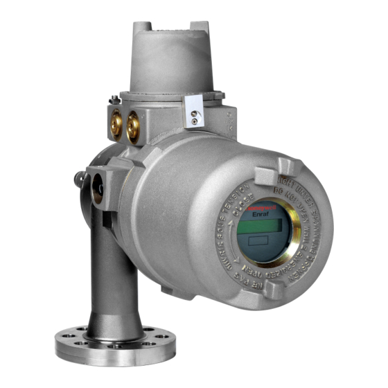
- Page 1 Advanced Technology Gauge July 2008 Part no. 4416.225 Rev. 6 Enraf B.V. P.O. Box 812 2600 AV Delft Netherlands Tel. : +31 15 2701 100 : +31 15 2701 111 E-mail : [email protected] Website : http://www.honeywellenraf.com Installation guide 854 ATG Page 1...
- Page 2 Preface Preface The Honeywell Enraf 854 ATG is a servo gauge which measures the liquid level and can also be programmed to measure two additional interface levels. This installation guide is intended for technicians involved in the mechanical and electrical installation of the Honeywell Enraf Series 854 ATG (Advanced Technology Gauge).
- Page 3 Safety Safety Safety aspects of 854 ATG Warning Do not use the instrument for anything else than its intended purpose. For medium pressure versions (till 6 bar), the 854 ATG drum compartment housing is of aluminium, and for chemical version it is of stainless steel. For high pressure version (max.
- Page 4 Safety Personal safety The technician must have basic technical skills to be able to safely install the equipment. When the 854 ATG is installed in a hazardous area, the technician must work in accordance with the (local) requirements for electrical equipment in hazardous areas. Warning In hazardous areas it is compulsory to use personal protection and safety gear such as: hard hat, fire-resistive overall, safety shoes, safety glasses and working gloves.
- Page 5 General precautions General precautions Caution During transport of the gauge the motor block should be locked. This is for protection of the weighing system. Caution The box in which the 854 arrives also contains the measuring drum. This is a precision measuring device and shall only be installed by a qualified commissioning engineer.
- Page 6 Mechanical installation Mechanical installation Note: The entire installation procedure shall be in accordance with national, local and company regulations. Preparation for transportation of the gauge Caution Do not transport the instrument with the motor unlocked. Refer to figure 1 for motor locking. Drum should be transported in original protective box.
- Page 7 Mechanical installation Orientation of 854 ATG gauge on tank Mount the gauge in one of the following two ways. Figure 2 Orientation of the gauge on a tank (top view) On a stilling well or guide pole, the orientation of the gauge may be chosen freely. Note: The weight of the 854 ATG for: - medium pressure version is : 16 kg (35 lbs);...
- Page 8 Mechanical installation Bolts Secure the gauge adapter by using appropriate bolts. *) Flange type Number of bolts Diameter x minimum length NW50, ND6 M12 x 50 NW50, ND40 M16 x 60 2", 150 lbs " x 3" (M16 x 80) 2", 300 lbs "...
- Page 9 Mechanical installation Grounding Warning For proper grounding of the 854 ATG, install a copper strip under one of the flange bolts for each flange. Place shark rings between flange and strip (figure 4). Figure 4 Example of flange ground Note: Also in case of tanks with cathodic protection, the 854 ATG must be grounded to the tank.
- Page 10 Electrical installation Electrical installation The entire electrical installation shall be in accordance with International Standard IEC 79-14 for electrical equipment to be installed in hazardous areas. Warning Make sure that all power to the instrument is switched off before opening the cover of the electronic and terminal compartment.
- Page 11 Electrical installation Preparing gauge for electrical installation Mains voltage selector Check whether voltage selector is set correctly as indicated on identification label of 854 ATG as well as for the presented supply. The voltage selector is located inside electronic compartment (on the top of backplane). It is marked with 'A' in figure 6.
- Page 12 Electrical installation External fusing The 854 ATG is internally fused on secondary side of transformer (fuses are located on GPS board). Therefore, external fuses must be installed in the mains supply cable to each 854 ATG. mains voltage fuse value (in accordance with IEC 127-2-3) 220 Vac or 230 Vac 315 mA slow 110 Vac or 130 Vac...
- Page 13 Electrical installation Grounding The 854 ATG housing should be properly grounded to the ground reference (generally the tank). This is a safety grounding requirement. Grounding can be performed by copper strips across the flanges (refer to section Grounding at mechanical installation), or by a ground wire. With last mentioned method, use one of the external ground terminals of the 854 ATG.
- Page 14 Maximum length: 10 km. Honeywell Enraf field bus lines may be interchanged. If local regulations allow, mains and Honeywell Enraf field bus lines may share one cable. Mind the isolation voltage of the cores in the cable; refer to the International Standard IEC 61010-1.
- Page 15 Electrical installation When the voltage exceeds 30 Vdc, an additional resistor is required. The permitted operational areas are shown in figure 9. Operational area 1 represents the area of operation without the need of an external loop resistance. Operational area 2 shows the area where a resistance is required.
- Page 16 Electrical installation Intrinsically safe options The cables for the intrinsically safe options shall only be fed through the cable entries at the side of the intrinsically safe (blue) terminals. Blue marked cables are recommended for the intrinsically safe options. Caution The intrinsically safe options described in this section are explosion-proof certified.
- Page 17 Electrical installation Device Cable requirements 977 Tank Side Indicator : Twisted pair and shielded; R = 5 Ω / line, maximum cable length 50 m (160 ft). GFC (Foundation™ Fieldbus) : Requires external supply 9 – 24 Vdc Nominal current 11 mA Maximum current (startup) 16.70 mA Water bottom probe : Twisted pair and shielded;...
- Page 18 Appendix Appendix A Dimensions 854 ATG (medium pressure and chemical version) Page 18 Installation guide 854 ATG...
- Page 19 Appendix Dimensions 854 ATG (high pressure version) Installation guide 854 ATG Page 19...
- Page 20 Appendix Appendix B Available adapters & calibration chambers Page 20 Installation guide 854 ATG...
- Page 21 Appendix Appendix C ATEX approval The terminal compartment of the 854 ATG level gauge has been ATEX approved as explosion- proof and as being increased safe. The type of cable glands that must used: For protection type increased safe EEx e approved glands are to be used. For protection type explosion proof EEx d approved glands or conduit are to be used.
- Page 22 Appendix Appendix D Related documents Instruction manual 854 ATG level gauge Instruction manual 854 density option Instruction manual SPU II Hard alarm output contacts Installation guide 762 VITO Interface & 764, 765 or 766 VITO temperature and/or water sensor Installation guide 977 Tank Side Indicator Instruction manual XPU-2 option RS-232C/RS-485 Instruction manual Temperature, Water bottom and Analog output options Instruction manual HIMS / HTG and vapour pressure (P3) measurement...
- Page 23 Notes Installation guide 854 ATG Page 23...
- Page 24 Webiste: www.honeywellenraf.com PO Box 812 2600 AV Delft The Netherlands We at Honeywell Enraf are committed to excellence. Information in this publication is subject to change without notice Enraf is a registered trade mark. Enraf B.V. Netherlands Page 24 Installation guide 854 ATG...