Emerson FB1100 Field Replacement Manual
Flow computer cpu module
Hide thumbs
Also See for FB1100:
- Instruction manual (88 pages) ,
- Quick start manual (35 pages) ,
- Field replacement manual (20 pages)
Quick Links
FB1100/FB1200 Flow Computer
CPU Module
Field Replacement Guide
For Part Numbers (Kits):
Remote Automation Solutions
FB1100/FB1200 Flow Computer CPU Module Field Replacement Guide
399134018-KIT: CPU (DC power only)
399393-01-0: CPU (with lithium battery board)
399381-01-1: CPU (with lead acid battery board)
399381-02-0: CPU (with lead acid battery board - Enersys)
D301802X012
November 2020

Related Manuals for Emerson FB1100


Summary of Contents for Emerson FB1100
- Page 1 FB1100/FB1200 Flow Computer CPU Module Field Replacement Guide D301802X012 November 2020 FB1100/FB1200 Flow Computer CPU Module Field Replacement Guide For Part Numbers (Kits): 399134018-KIT: CPU (DC power only) 399393-01-0: CPU (with lithium battery board) 399381-01-1: CPU (with lead acid battery board) ...
-
Page 2: System Training
Our full-time professional instructors can conduct classroom training at several of our corporate offices, at your site, or even at your regional Emerson office. You can also receive the same quality training via our live, interactive Emerson Virtual Classroom and save on travel costs. For our complete schedule and further information, contact the Remote Automation Solutions Training Department at 800-338-8158 or email us at [email protected]. -
Page 3: Replacing The Cpu Module
See the following compatibility chart. Important Use only accessories (batteries) supplied with the flow computer or sold by Emerson as spare parts for this flow computer. Substituting a part you obtain elsewhere (such as a battery) voids your certification. - Page 4 Flow Computer CPU Board with lithium battery board Field Installed Accessory Kit Part No. 399393-01-1 for use with UL Listed Model Series FB1100. Flow Computer CPU board with solar/lead acid battery charge board Field Installed Accessory Kit Part No. 399381-01-0 for use with UL Listed Model Series FB1100 and FB1200.
- Page 5 Flow Computer CPU board with solar/Enersys lead acid battery charge board Field Installed Accessory Kit Part No. 399381-02-0 for use with UL Listed Model Series FB1100 and FB1200. CAUTION If your flow computer uses lead acid battery pack 399186-01-8 and you need to replace the CPU and battery charge board, you must select kit 399381-01-0 because the 399186-01-8 battery is not supported by the Enersys charge board.
- Page 6 FB1100/FB1200 Flow Computer CPU Module Field Replacement Guide D301802X012 November 2020 Front End Cap (unscrewed) Rear End Cap (removed) Unplug terminal block TB1 to disconnect main power. TB1 has either six connectors or eight connectors. See the graphics below for detail:...
- Page 7 FB1100/FB1200 Flow Computer CPU Module Field Replacement Guide D301802X012 November 2020 TB1 (Eight connectors) With a #2 Phillips-head screwdriver, loosen the two captive fastening screws in the recessed areas of the battery pack enclosure. Note Not all units include an internal battery but the battery enclosure is always present.
- Page 8 FB1100/FB1200 Flow Computer CPU Module Field Replacement Guide D301802X012 November 2020 Captive Screws With a #1 Phillips-head screwdriver, loosen the two bottom captive fastening screws on the HMI module. Leave the two top screws on the HMI module connected to the battery pack enclosure.
- Page 9 FB1100/FB1200 Flow Computer CPU Module Field Replacement Guide D301802X012 November 2020 HMI Module (removed) If the battery pack holds an internal battery, disconnect it. Internal Battery (disconnected) Set the battery pack enclosure and HMI module assembly aside. Remove the SRAM backup battery; set it aside in a safe place.
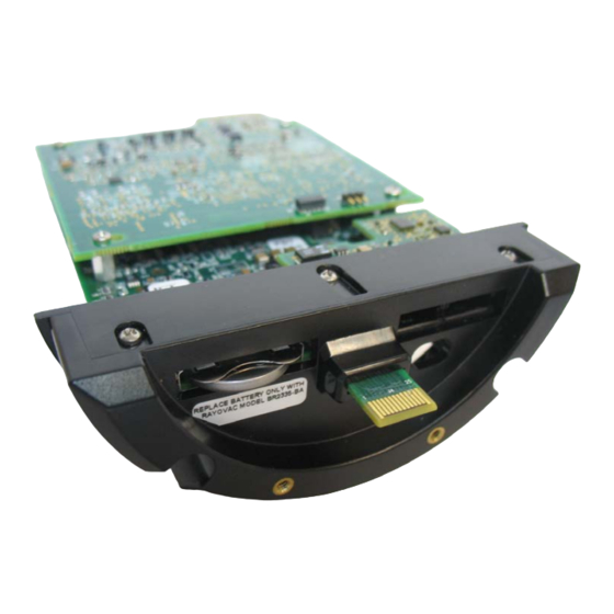
- Page 10 FB1100/FB1200 Flow Computer CPU Module Field Replacement Guide D301802X012 November 2020 SRAM Battery (removed) With a #2 Phillips-head screwdriver, loosen the two captive fastening screws in the plastic bezel that hold the CPU module in place. Bezel Fastening Screws Grasp the plastic bezel and gently pull the CPU module out of the housing.
- Page 11 FB1100/FB1200 Flow Computer CPU Module Field Replacement Guide D301802X012 November 2020 CPU Module (removed) Use a 3/32-inch flathead screwdriver to separate the internal wire connector plug from the plug on the bottom of the CPU module. Internal Wire Connector Plug on CPU Module...
- Page 12 FB1100/FB1200 Flow Computer CPU Module Field Replacement Guide D301802X012 November 2020 Correct IO Expansion Board Screw Locations Snap the internal wire connector plug (from Step 13) onto the mating plug on the bottom of the new (replacement) CPU module and gently slide the new CPU module into the housing, being careful not to pinch wires.
- Page 13 FB1100/FB1200 Flow Computer CPU Module Field Replacement Guide D301802X012 November 2020 If applicable, tighten the retaining clamp onto each end cap using a 3mm hexagonal wrench. When tightening, torque to 10 to 12 in-lbs (1.1 to 1.4 N-m).
- Page 14 Emerson Automation Solutions Remote Automation Solutions Emerson FZE P.O. Box 17033 © 2018-2020 Remote Automation Solutions, a business unit of Emerson Automation Jebel Ali Free Zone – South 2 Solutions. All rights reserved. Dubai U.A.E. This publication is for informational purposes only. While every effort has been made to ensure...