Emerson FB1100 Instruction Manual
Flow computer
Hide thumbs
Also See for FB1100:
- Instruction manual (88 pages) ,
- Quick start manual (35 pages) ,
- Field replacement manual (20 pages)

Related Manuals for Emerson FB1100


Summary of Contents for Emerson FB1100
- Page 1 Emerson FB1100 Flow Computer Instruction Manual Part Number: D301752X012 July 2017 Emerson FB1100 Flow Computer Instruction Manual Remote Automation Solutions...
-
Page 2: Returning Equipment
Device Safety Considerations Reading these Instructions Before operating the device, read these instructions carefully and understand their safety implications. In some situations, improperly using this device may result in damage or injury. Keep this manual in a convenient location for future reference. Note that these instructions may not cover all details or variations in equipment or cover every possible situation regarding installation, operation, or maintenance. -
Page 3: Table Of Contents
Emerson FB1100 Flow Computer Instruction Manual D301752X012 July 2017 Contents Section 1: Introduction .............. 1 Safety Labels ........................3 Features ........................3 Central Processing Unit (CPU) ..................4 1.3.1 Memory ......................4 ... - Page 4 Emerson FB1100 Flow Computer Instruction Manual D301752X012 July 2017 2.10.2 Standard Power Mode ..................26 2.11 Connecting Power ....................... 27 2.11.1 Connecting DC Power ..................27 2.11.2 Connecting Battery Power ................28 ...
- Page 5 Emerson FB1100 Flow Computer Instruction Manual D301752X012 July 2017 Appendix A: Special Instructions for Class I Division 2 Locations .. 59 Appendix B: Special Instructions for Class I Division 1 Locations .. 63 Appendix C: ATEX Non-Sparking Zone 2 Certifications ....69 ...
-
Page 7: Section 1: Introduction
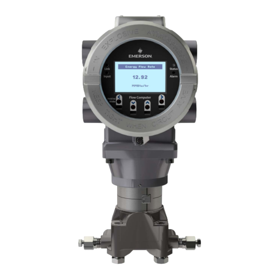
Autonomous Measurement Mode The Emerson FB1100 flow computer measures pressure, differential pressure, and temperature for a single meter run of natural gas. This manual describes how to install and configure the Emerson FB1100 flow computer hardware. For information on using the FBxConnect configuration software, see the online help that accompanies FBxConnect. - Page 8 Emerson FB1100 Flow Computer Instruction Manual D301752X012 July 2017 Figure 1-1: FB1100 Flow Computer HMI module Front end cap (cover) Data plate Rear end cap (cover) Conduit fittings Enclosure Sensor module Introduction...
-
Page 9: Safety Labels
Failure to do so may result in injury to personnel or cause damage to the equipment. SAFETY FIRST General instructions and safety reminders. Features The FB1100 flow computer includes the following key features: Enclosure suitable for use in Class I Division 1 explosion proof and Ex d Zone 1 flame-proof environments ... -
Page 10: Central Processing Unit (Cpu)
128 MB FLASH Holds firmware image and configuration files Explosion-proof Enclosure The FB1100 includes an explosion-proof enclosure. The enclosure consists of the main housing, two threaded covers, and four conduit entry points. The four conduit entry points are ¾ in NPT pipe threaded holes that permit entry of field conduit for I/O and communication wiring. -
Page 11: Power Options
D301752X012 July 2017 The FB1100 has North American certification for Class I Division 1 Groups C and D (explosion proof) and Class I Division 2 Groups A, B, C and D (non-incendive) hazardous locations or non-hazardous locations. See Appendix A and Appendix B for more information. -
Page 12: Communications
Emerson FB1100 Flow Computer Instruction Manual D301752X012 July 2017 Required when using autonomous measurement mode In autonomous measurement mode allows operation for one year Communications The flow computer includes three serial communication ports. The serial ports allow communication using DNP3, Modbus, BSAP, and ROC protocols. -
Page 13: Mobile Scada
Emerson FB1100 Flow Computer Instruction Manual D301752X012 July 2017 Figure 1-2: HMI Module with LCD Figure 1-3: HMI Module without LCD Note If your flow computer does not include the LCD option (shown in Figure 1-2), you still have the... -
Page 14: Software Tools
1.11 Base Firmware The base firmware in the FB1100 flow computer measures pressure (P), differential pressure (DP), and temperature (T) for a single meter run. It performs gas flow calculations based on those inputs in either U.S., metric, or natural gas international units. Use the FBxConnect configuration software to configure the various features and functions of the firmware. -
Page 15: Autonomous Measurement Mode
1.12 Autonomous Measurement Mode You can configure the FB1100 flow computer to operate as a low power measurement device that operates independently for one year. In this autonomous measurement mode, the FB1100 operates similarly to earlier generation chart recorders, collecting data from non-critical, low-flow applications and storing it for later retrieval. -
Page 17: Section 2: Installation
Appendix A contains special information for Class I Division 2 installations; Appendix B contains special information for Class I Division 1 installations. For Europe the FB1100 has certifications for Ex d Zone 1 flame-proof and for Ex nA Zone 2 non- sparking installations and non-hazardous locations only. Appendix C contains special information for Ex nA Zone 2 installations;... -
Page 18: Environmental Specifications
D301752X012 July 2017 Environmental Specifications This section summarizes the environmental specifications for the device. For full details, refer to the product data sheet FB1100 Flow Computer (D301781X012). Table 2-1: Environmental Specifications Specification Range -40°C to +80 °C (-40 °F to +176 °F ) - no battery, C1D1/C1D2 -40°C to +60 °C (-40°F to +140 °F ) –... -
Page 19: Site Considerations
Emerson FB1100 Flow Computer Instruction Manual D301752X012 July 2017 Site Considerations The flow computer must reside in an accessible location for configuration and service. Refer to the dimensional drawings for information on the space required. Figure 2-1: FB1100 Dimensions ... -
Page 20: General Wiring Guidelines
Emerson FB1100 Flow Computer Instruction Manual D301752X012 July 2017 General Wiring Guidelines The flow computer’s pluggable terminal blocks use compression-type terminals that accommodate wire between 28 and 12 AWG. When making a connection, insert the bare end of the wire (approx. 1/4" max) into the clamp adjacent to the screw and secure the screw. -
Page 21: Removing The Front Or Rear End Caps
Emerson FB1100 Flow Computer Instruction Manual D301752X012 July 2017 Figure 2-3. Retaining Clamp in Place To loosen or tighten the screw, use a 3mm hexagonal wrench. When tightening, torque to 12 in-lbs (1.4 N m). Figure 2-4. Retaining Clamp and Screw 2.6.2... -
Page 22: Replacing The Front Or Rear End Caps
Emerson FB1100 Flow Computer Instruction Manual D301752X012 July 2017 Grasp the end cap (front or rear). Figure 2-6: Front (left) and Rear (right) End caps Unscrew the end cap turning it counter-clockwise until it comes off. Set it aside in a safe location. -
Page 23: Mounting The Enclosure
Only use bolts supplied with the flow computer or sold by Emerson Remote Automation Solutions as spare parts. Refer to the figure for common flow computer assemblies with the bolt length required for proper flow computer installation. -
Page 24: Torque Values For The Flange And Flange
Emerson FB1100 Flow Computer Instruction Manual D301752X012 July 2017 Figure 2-10: Transmitter with Traditional Flange and Optional Flange Adapters Use the following bolt installation procedure: Carbon steel bolts do not require lubrication. Stainless steel bolts are factory-coated with a lubricant to ease installation. Do not apply any additional lubricant when installing either type of bolt. -
Page 25: O-Rings With Flange Adapters
Emerson FB1100 Flow Computer Instruction Manual D301752X012 July 2017 Figure 2-11: Proper Bolt Installation Bolt Sensor module 2.7.2 O-rings with Flange Adapters DANGER Failure to install proper flange adapter O-rings may cause process leaks, which can result in death or serious injury. Only use the O-ring that is designed for its specific flange adapter. -
Page 26: Direct Mount
Emerson FB1100 Flow Computer Instruction Manual D301752X012 July 2017 2.7.3 Direct Mount Direct mount installations use either a traditional mounting kit or a coplanar mounting kit. Mount the flow computer directly to the natural gas pipeline only if the pipeline includes a process manifold. -
Page 27: Indirect Mount
Emerson FB1100 Flow Computer Instruction Manual D301752X012 July 2017 Figure 2-14: Coplanar Mounting Kit Tubular L-shaped bracket 3/8-16 x 1 ½ in wire screw (2) – Apply Killark ® LUBG-6 Thread Lubricant to threads. Torque screws to 30 in-lbs (3.4 N m) Split 5/16 washer (2) 5/16-18 keps nut (2). -
Page 28: Rotating The Housing
Emerson FB1100 Flow Computer Instruction Manual D301752X012 July 2017 Figure 2-15: Inline Mounting Kit Pipe mounting bracket 2 ½ inch x 5/18-18 thread 300-series U-bolt 5/16 flat lock washer (2) 5/16-18 300 series passivate hex nut (2) - Apply Loctite 222 Low Strength Purple Threadlocker to threads. - Page 29 Emerson FB1100 Flow Computer Instruction Manual D301752X012 July 2017 Figure 2-16: Housing Rotation Set Screw (1 each side) Set Screw (one each side) DANGER EXPLOSION HAZARD: Ensure the area in which you perform this operation is non-hazardous. Performing this operation in a hazardous area could result in an explosion.
-
Page 30: Grounding The Device
Emerson FB1100 Flow Computer Instruction Manual D301752X012 July 2017 Grounding the Device The flow computer includes a grounding lug on the terminal plate. Figure 2-17: Ground Lug Ground Lug DANGER EXPLOSION HAZARD: Ensure the area in which you perform this operation is non-hazardous. -
Page 31: Terminal Plate
2.10 Power Modes To keep power consumption to a minimum, especially for remote sites, the FB1100 can run in two different power modes – Low Power Mode (4 or 8 MHz CPU clock speed) or Standard Power Mode (60 MHz CPU clock speed). -
Page 32: Standard Power Mode
Table 2-4, the flow computer cannot operate in low power mode and automatically runs in standard power mode. 2.10.2 Standard Power Mode When serial communication is active the FB1100 operates in standard power mode. The unit also uses standard power mode when: The HMI module display is ON ... -
Page 33: Connecting Power
Emerson FB1100 Flow Computer Instruction Manual D301752X012 July 2017 Table 2-5: Typical Power Usage – Standard Power Mode at room temperature Power Power Power Usage Usage Usage Description (mW) at (mW) at (mW) at 6Vdc 12Vdc 24Vdc Base flow computer with integral multivariable DP and pressure... -
Page 34: Connecting Battery Power
Emerson FB1100 Flow Computer Instruction Manual D301752X012 July 2017 Figure 2-19: DC Power Connections 2.11.2 Connecting Battery Power DANGER EXPLOSION HAZARD: Ensure the area in which you perform this operation is non-hazardous. Performing this operation in a hazardous area could result in an explosion. -
Page 35: Installing The Optional Solar Panel
Emerson FB1100 Flow Computer Instruction Manual D301752X012 July 2017 2.12 Installing the Optional Solar Panel If you purchased the lead acid battery/solar panel kit for main power, you need to install the supplied 6W solar panel. If you purchased the lead acid battery with a solar regulator but you are supplying your own solar panel, follow the manufacturer’s instructions for remote mounting. -
Page 36: Mounting The Solar Panel (Integral Mount)
Emerson FB1100 Flow Computer Instruction Manual D301752X012 July 2017 Figure 2-21: Attaching Mounting Hardware to the Solar Panel 6V, 6W solar panel Aluminum tilt bracket (2) 10-32 x ½ pan head screw (4). Note: Matching hex nuts and washers not visible in this graphic;... - Page 37 Emerson FB1100 Flow Computer Instruction Manual D301752X012 July 2017 Figure 2-22: Integral Mounted Solar Panel 6V, 6W solar panel Aluminum tilt bracket (2) 10-32 x ½ pan head screw (4). 5/16 flat washer (4); only two visible in this graphic 5/16-18 x .75 LG hex head bolt (2)
-
Page 38: Mounting The Solar Panel (Remote Mount)
Emerson FB1100 Flow Computer Instruction Manual D301752X012 July 2017 ® 1. Apply Loctite 380™ Black Instant Adhesive to threads of elbow pipe (Item 15). Attach elbow pipe (Item 15) to the flow computer conduit opening (Item 16); torque to 50 in-lbs (5.6 N m). -
Page 39: Connecting Solar Power
Emerson FB1100 Flow Computer Instruction Manual D301752X012 July 2017 Figure 2-23: Remote Mounted (pole mounted) Solar Panel 6V, 6W solar panel mounting bracket U-bolt 1 1/8 OD x ¼ -20 x 1 inch long thread pole (customer supplied) 2.12.4 Connecting Solar Power DANGER EXPLOSION HAZARD: Ensure the area in which you perform this operation is non-hazardous. -
Page 40: Adjusting The Optional Solar Panel Tilt Angle
Emerson FB1100 Flow Computer Instruction Manual D301752X012 July 2017 Figure 2-24: Wiring Solar Power Restriction The solar panel and lead acid battery combination cannot be used with ATEX/IECEx applications. 2.12.5 Adjusting the Optional Solar Panel Tilt Angle DANGER EXPLOSION HAZARD: Ensure the area in which you perform this operation is non-hazardous. -
Page 41: Connecting Communication Ports
Emerson FB1100 Flow Computer Instruction Manual D301752X012 July 2017 Point the solar panel surface due south (in the northern hemisphere) or due north (in the southern hemisphere) at an angle determined by the latitude of the site. Table 2-6... -
Page 42: Connecting
Emerson FB1100 Flow Computer Instruction Manual D301752X012 July 2017 Figure 2-26: Connecting a Device to COM1 Using RS-232 RS-232 port (COM1) on FB device RS-232 port on external device When connecting COM1 to another device using RS-422, use a cable with configurations as shown... - Page 43 Emerson FB1100 Flow Computer Instruction Manual D301752X012 July 2017 Figure 2-28: Connecting a Device to COM1 Using RS-485 RS-485 port (COM1) on FB device RS-485 port on external device Regardless of the interface standard (RS-232, RS-422, or RS-485) you must use FBxConnect to configure the port for proper usage.
-
Page 44: Connecting To Com2 And Com3
Emerson FB1100 Flow Computer Instruction Manual D301752X012 July 2017 2.13.2 Connecting to COM2 and COM3 COM2 and COM3 operate identically. Each can be configured for either RS-232 or RS-485 communication. When connecting COM2 or COM3 to an RS-232 port on another device (a PC or another... - Page 45 Emerson FB1100 Flow Computer Instruction Manual D301752X012 July 2017 When connecting COM2 or COM3 to an RS-485 port on another device (for example, a transmitter), use a cable with configurations as shown in Figure 2-30: Figure 2-30: Connecting a Device to COM2 or COM3 Using RS-485 ...
-
Page 46: Connecting The Rtd
Emerson FB1100 Flow Computer Instruction Manual D301752X012 July 2017 2.14 Connecting the RTD DANGER EXPLOSION HAZARD: Ensure the area in which you perform this operation is non-hazardous. Performing this operation in a hazardous area could result in an explosion. RTD connections reside on the terminal plate under the rear cover. The flow computer supports 2- wire, 3-wire, and 4-wire operation. -
Page 47: Wiring The Digital Output
Emerson FB1100 Flow Computer Instruction Manual D301752X012 July 2017 2.15 Wiring the Digital Output DANGER EXPLOSION HAZARD: Ensure the area in which you perform this operation is non-hazardous. Performing this operation in a hazardous area could result in an explosion. -
Page 49: Section 3: Operation
Emerson FB1100 Flow Computer Instruction Manual D301752X012 July 2017 Section 3: Operation This section covers the following topics: Powering Up/Powering Down the Device Establishing Communications Communicating using the HMI Module This section describes day-to-day operation of the flow computer including how to turn it on and off and how to communicate with it. -
Page 50: Communicating With A Laptop Using One Of The Serial Ports
Decide which communication protocol you will use. This could be DNP3, ROC, or BSAP. See these documents for more information: Emerson FB Flow Computer DNP3 Protocol Specifications Manual (D301806X012) ROC Protocol Specifications Manual for (for Emerson FBx-series) (D301828X012) ... -
Page 51: Communicating Using The Hmi Module
Emerson FB1100 Flow Computer Instruction Manual D301752X012 July 2017 ® WiFi must be configured and working on your laptop PC. Your laptop PC must have Field Tools software with FBxConnect installed. You must know a valid username/password combination for the flow computer. - Page 52 Emerson FB1100 Flow Computer Instruction Manual D301752X012 July 2017 Figure 3-1: Waking up the Display If prompted, login using a valid username/password combination (Data Entry Mode). For information on how the buttons work, see Table 3-1. The display enters Screen Saver Mode where it sequentially presents a series of screens showing details about the meter run flow rates, totals, and current process variables.
- Page 53 Emerson FB1100 Flow Computer Instruction Manual D301752X012 July 2017 Figure 3-2: Infrared (IR) Button Location Left Infrared (IR) Button Down Infrared (IR) Button Up Infrared (IR) Button Right Infrared (IR) Button Note When using the IR buttons, aim your finger at the round spot just below the arrow.
-
Page 54: Infrared (Ir) Buttons On Hmi Module
Emerson FB1100 Flow Computer Instruction Manual D301752X012 July 2017 Table 3-1: Infrared (IR) Buttons on HMI Module Button Use to Screen Saver Mode Tap once to move (UP) or (DOWN) one item through list of parameters. Hold to stay on current parameter. -
Page 55: Section 4: Service And Troubleshooting
Emerson-authorized repair facility. Important Only use batteries supplied with the flow computer or sold by Emerson as spare parts for this flow computer. If you substitute a battery you obtain elsewhere you will void your certification unless it is the identical part from the same manufacturer as that supplied with the flow computer from Emerson. -
Page 56: Returning The Unit For Repairs
Other types of repairs cannot be performed in the field. In those cases, you must ship the unit to an Emerson-authorized repair facility. Contact Emerson Remote Automation Solutions for a return authorization number and instructions for where to ship the unit. -
Page 57: Interpreting The Status Leds
Emerson FB1100 Flow Computer Instruction Manual D301752X012 July 2017 WARNING International safety regulations restrict the shipment of lithium batteries. If you need to return the flow computer, remove the lithium battery before you ship the unit. Failure to remove the lithium battery may delay or prevent shipment of the flow computer. - Page 58 Emerson FB1100 Flow Computer Instruction Manual D301752X012 July 2017 Table 4-1: LED Descriptions Color/State Meaning An active wired Ethernet connection Link LED GREEN exists. Otherwise it is off. (FB1200/FB2200 only) Input LED GREEN One of the IR buttons is being pressed.
-
Page 59: Switch And Buttons
Emerson FB1100 Flow Computer Instruction Manual D301752X012 July 2017 Switch and Buttons A momentary switch and two push buttons on the HMI module provide trouble-shooting options for the flow computer. DANGER EXPLOSION HAZARD: Never remove end cap(s) in a hazardous location. Removing end cap(s) in a hazardous location could result in an explosion. -
Page 60: Replacing The Main Battery Pack
Emerson FB1100 Flow Computer Instruction Manual D301752X012 July 2017 Figure 4-3: Captive Fastening Screws Grasp the HMI module and remove it by gently pulling it straight out away from the unit. To replace the HMI module, line up the printed circuit board (PCB) with the slot on the back and gently press it back on. - Page 61 Emerson FB1100 Flow Computer Instruction Manual D301752X012 July 2017 DANGER EXPLOSION HAZARD: Ensure the area in which you perform this operation is non-hazardous. Performing this operation in a hazardous area could result in an explosion. DANGER EXPLOSION HAZARD: Do not disconnect equipment unless power has been removed or the area is known to be non-hazardous.
-
Page 62: Removing/Replacing The Sram Battery
Emerson FB1100 Flow Computer Instruction Manual D301752X012 July 2017 Figure 4-5: Removing the Battery Pack Connect the new battery to the open connector. Route the wires so they are in the recessed area. Make sure the wires won’t get caught in the end cap threads. - Page 63 Emerson FB1100 Flow Computer Instruction Manual D301752X012 July 2017 DANGER Ensure the flow computer is in a non-hazardous area. Never remove end caps in a hazardous area. DANGER Do not disconnect equipment unless power has been removed or the area is known to be non- hazardous.
-
Page 64: Upgrading System Firmware
Emerson FB1100 Flow Computer Instruction Manual D301752X012 July 2017 Upgrading System Firmware Periodically Emerson releases new system firmware for the flow computer to introduce new features or update system functions. You must know a valid username/password combination for the flow computer to complete this process. -
Page 65: Special Instructions For Class I Division 2 Locations
An RTD may be supplied with the Emerson FB1100 flow computer. Connection to the RTD is approved as a non-incendive circuit so that Division 2 wiring methods are not required. - Page 66 Emerson FB1100 Flow Computer Instruction Manual D301752X012 July 2017 Figure A-1: Data Plate (NO BATTERY) – Class I Division 2 Non-incendive (UL) Special Instructions for Class I Division 2 Locations...
- Page 67 Emerson FB1100 Flow Computer Instruction Manual D301752X012 July 2017 Figure A-2: Data Plate (LEAD ACID BATTERY) – Class I Division 2 Non-incendive (UL) Special Instructions for Class I Division 2 Locations...
- Page 68 Emerson FB1100 Flow Computer Instruction Manual D301752X012 July 2017 Figure A-3: Data Plate (LITHIUM BATTERY) – Class I Division 2 Non-incendive (UL) Special Instructions for Class I Division 2 Locations...
-
Page 69: Special Instructions For Class I Division 1 Locations
An RTD may be supplied with the Emerson FB1100 flow computer. Connection to the RTD is approved as a non-incendive circuit. - Page 70 Emerson FB1100 Flow Computer Instruction Manual D301752X012 July 2017 DANGER EXPLOSION HAZARD: Substitution of any components may impair suitability for Class I, Division 1 or Class I, Division 2. DANGER EXPLOSION HAZARD: Do not replace batteries unless power has been switched off or the area is known to be non-hazardous.
- Page 71 Emerson FB1100 Flow Computer Instruction Manual D301752X012 July 2017 Figure B-1: Data Plate (NO BATTERY) – Class I Division 1 Explosion Proof (UL) Special Instruction for Class I Division 1 Locations...
- Page 72 Emerson FB1100 Flow Computer Instruction Manual D301752X012 July 2017 Figure B-2: Data Plate (LEAD ACID BATTERY) – Class I Division 1 Explosion Proof (UL) Special Instructions for Class I Division 1 Locations...
- Page 73 Emerson FB1100 Flow Computer Instruction Manual D301752X012 July 2017 Figure B-3: Data Plate (LITHIUM BATTERY) – Class I Division 1 Explosion Proof (UL) Special Instruction for Class I Division 1 Locations...
-
Page 75: Atex Non-Sparking Zone 2 Certifications
D301752X012 July 2017 Appendix C: ATEX Non-Sparking Zone 2 Certifications This appendix includes notes on ATEX certifications. For full details, please refer to the Emerson FB1100 Flow Computer Safe Use Instructions (D301768X012). Follow these Conditions of Safe Use: Provision shall be made to prevent the rated voltage being exceeded by the transient disturbances of more than 140% of the peak rated voltage. - Page 76 Emerson FB1100 Flow Computer Instruction Manual D301752X012 July 2017 Figure C-1: Data Plate – ATEX nA Non-Sparking ATEX Non-Sparking Zone 2 Certifications...
-
Page 77: Atex Flame-Proof Zone 1 Certifications
July 2017 Appendix D: ATEX Flame-Proof Zone 1 Certifications The data plate and certain conditions of use are shown below. For full details refer to the Emerson FB1100 Flow Computer Safe Use Instructions (D301768X012). Figure D-1: Data Plate – ATEX Ex d Flame-proof... - Page 78 Specific conditions of use / Schedule of Limitations: Contact your authorized sales and service representative for any maintenance or repair beyond the maintenance of the FB1100 flow computer. Do not alter or disassemble any of the flameproof joints of the FB1100 flow computer.
-
Page 79: Index
Emerson FB1100 Flow Computer Instruction Manual D301752X012 July 2017 Index A Covers clamp ..............14 Application software ..........8 removing ............14, 15 ATEX certification replacing ............. 16 notes on Zone 1 ........... 71 CPU ................4 notes on Zone 2 ........... 69 Autonomous Measurement Mode ...... -
Page 80: July
3-1. Waking up the Display ........46 Inline mounting kit ..........22 3-2. Infrared (IR) Button Location ......47 Installation .............. 11 4-1. FB1100 Flow Computer Components .... 50 4-2. LED Locations ..........51 L 4-3. Captive Fastening Screws ......54 4-4. - Page 81 Emerson FB1100 Flow Computer Instruction Manual July 2017 D301752X012 inline ..............22 amount of ............. 4 traditional flange ..........20 clearing ............... 53 Status LEDs ............. 51 N Switch ..............53 Non-sparking System firmware ATEX Zone 2 certification notes ......69 upgrading the .............
- Page 82 Emerson Automation Solutions Remote Automation Solutions Emerson FZE P.O. Box 17033 © 2017 Remote Automation Solutions, a business unit of Emerson Automation Solutions. All Jebel Ali Free Zone – South 2 rights reserved. Dubai U.A.E. This publication is for informational purposes only. While every effort has been made to ensure...