
Related Manuals for Hitachi MICRO-EHV+


Summary of Contents for Hitachi MICRO-EHV+
- Page 1 HITACHI PROGRAMMABLE CONTROLLER IEC 61131-3 Compliant PLC APPLICATION MANUAL (SERVICE MANUAL) NJI-611B(X)
- Page 2 ・Person handling PLC ・Manager after installing PLC Warning (1) Reproduction of the contents of this manual, in whole or in part, without written permission of Hitachi-IES, is prohibited. (2) The content of this document may be changed without notice. (3) While efforts have been made to be accurate, if any wrong or missing information is found, please contact us.
- Page 3 Safety Precautions Read this manual and related documents thoroughly before installing, operating, performing preventive maintenance or performing inspection, and be sure to use the unit correctly. Use this product after acquiring adequate knowledge of the unit, all safety information, and all cautionary information. Also, make sure this manual enters the possession of the chief person in charge of safety maintenance.
- Page 4 2. Wiring REQUIRED The PLC must be grounded (FE terminal). Failure to do so could result in injury to personnel or causing it to malfunction. CAUTION Always use the power supply voltage listed in specifications. Using other voltage may damage the equipment or ...
- Page 5 Revision History Description of revision Date of Manual number revision The first edition Feb. 2014 NJI-611(X) EtherCAT master and Modbus -TCP master added Feb. 2015 NJI-611A(X) 20-point Basic unit added and IDE updated to HX -CODESYS Oct. 2019 NJI-611B(X)
- Page 6 MEMO...
-
Page 7: Table Of Contents
Table of Contents Chapter 1 Introduction 1-1 to 1-2 1.1 Unpacking ............................. 1-1 1.2 Instruction Manuals ........................1-1 1.3 System overview ........................... 1-2 Chapter 2 Specifications 2-1 to 2-48 2.1 General specifications ........................2-1 2.2 Performance specifications ......................2-2 2.3 EtherCAT master specifications ....................2-3 2.4 Product lineup .......................... - Page 8 Chapter 3 Programming 3-1 to 3-94 3.1 Installation ............................. 3-1 3.1.1 System Requirements ...................... 3-1 3.1.2 Installation of HX-CODESYS ................... 3-1 3.1.3 Installation of USB driver ....................3-3 3.2 Startup............................3-5 3.3 I/O Configuration ........................... 3-7 3.3.1 Scan For Devices for expansion units ................3-7 3.3.2 Option board ........................
- Page 9 3.21 Option board ..........................3-74 3.21.1 Supported function ......................3-74 3.21.2 Port number setting ......................3-75 3.21.3 Analog input/output setting ....................3-75 3.21.4 Modbus-RTU communication ..................3-77 3.21.5 General purpose communication ..................3-77 3.22 USB program transfer ........................3-78 3.22.1 Download from USB to PLC ..................... 3-78 3.22.2 Upload from PLC to USB ....................
- Page 10 MEMO...
-
Page 11: Unpacking
Chapter 1 Introduction Thank you very much for choosing Hitachi Programmable Controller (hereinafter referred to as PLC), MICRO-EHV+ series PLC. Unpacking (1) Installation of a battery The battery for MICRO-EHV+ series PLC is optional. If you need real time clock function or retentive data memory, you need to purchase it. -
Page 12: System Overview
EHV-CODESYS and HX-CODESYS are IEC61131-3 compliant programming software for MICRO-EHV+ series PLC. “CODESYS” is a Trademark of the company 3S-Smart Software Solutions GmbH. “EHV-CODESYS” and “HX-CODESYS” are same tool as “CODESYS” however, Hitachi specific device description files and libraries are preinstalled. -
Page 13: Chapter 2 Specifications 2-1 To
○ Noise voltage 1,500 Vpp, Noise pulse width 100 ns, 1μs (Noise input by a noise simulator across input terminals of a power module according to measuring method of Noise resistance Hitachi-IES.) ○ Static noise 3,000 V at electrode part Certifications CE, RCM 20 MΩ... -
Page 14: Performance Specifications
Chapter 2 Specifications Performance specifications Table 2.2 Performance specifications Specification Item MV-*20** / MV-*40** / MV-*64** User program memory 1MB (*1) Source file memory Data memory (non retain) 640KB Data memory (retain) 256KB (incl. 64KB persistent variables) No. of expansion unit No. -
Page 15: Ethercat Master Specifications
Chapter 2 Specifications EtherCAT master specifications Table 2.4 EtherCAT master specifications Items Specifications Communication protocol EtherCAT protocol Supported services CoE (process data communications and SDO communications) Synchronization None (DC is not supported) Physical layer 100BASE-TX Modulation Baseband Baud rate 100M bits/s (100BASE-TX) Duplex mode Full / Auto Topology... -
Page 16: Product Lineup
Chapter 2 Specifications Product lineup Table 2.5 List of system equipment Product Type Specification I/O type 64 Points MV-A64DR 100/200 V AC, DC input×40, Relay output×24 Basic unit MV-D64DR 24 V DC, DC input×40, Relay output×24 MV-D64DT 24 V DC, DC input×40, Transistor output (sink) ×24 MV-D64DTPS 24 V DC, DC input×40, Transistor output (source) ×24 (20 points with short circuit protection) - Page 17 Chapter 2 Specifications Product Type Specification I/O type Thermocouple EH-D6ETC 24 V DC, Thermocouple input×4, Analog output×2 Expansion EH-D4ETC 24 V DC, Thermocouple input×4 unit Option OBV-NES RS-485 communication OptionBoard board OBV-485A RS-485 communication with Analog input 2 ch. (10-bit) OptionBoard OBV-485TAI RS-485 communication with Analog input 2 ch.
-
Page 18: Current Consumption
Chapter 2 Specifications Current consumption Table 2.6 List of current consumption Consumption current (A) Type weight (g) 100VAC 264VAC 24VDC Remarks Steady-state Steady-state Steady-state MV-A64DR MV-D64DR MV-D64DT MV-D64DTPS MV-A40DR MV-D40DR MV-D40DT MV-D40DTPS MV-A20DR MV-D20DR MV-D20DT MV-D20DTPS EH-A64EDR EH-D64EDR EH-D64EDT EH-D64EDTPS EH-A28EDR 0.06 EH-D28EDR... -
Page 19: Input Specifications
Chapter 2 Specifications Input specifications Specification Item Internal circuit diagram bit 0, 2, 4, 6, 8 Others Input voltage 24V DC Allowable input voltage range 0 to 30V DC Input impedance Approx. 2.7 kΩ Approx. 4.7 kΩ Input current 8 mA typical 4.8 mA typical 18 VDC / 3.3mA... -
Page 20: Output Specifications
Chapter 2 Specifications Output specifications (1) Relay output (All output on MV-*64DR, MV-*40DR, MV-*20DR) Item Specifications Internal circuit diagram Rated load voltage 5 to 250V AC, 5 to 30V DC Minimum switching current 1 mA (5V DC) 1 circuit 2A (24V DC, 240V AC) Maximum load current 1 common... - Page 21 Chapter 2 Specifications (2) DC output (Output 0 to 3 on MV-D64DT, MV-D40DT, MV-D20DT) Item Specifications Internal circuit diagram Output specifications Transistor output (sink type) Rated load voltage 24 / 12 V DC (+10%, -15%) Minimum switching current 10 mA Leak current 0.1 mA (max.) Maximum...
- Page 22 Chapter 2 Specifications (4) DC output (Output 0 to 3 on MV-D64DTPS, MV-D40DTPS, MV-D20DTPS) Item Specifications Internal circuit diagram Output specifications Transistor output (Source type) Rated load voltage 24 / 12 V DC (+10%, -15%) Minimum switching current 10 mA Leak current 0.1 mA (max.) Maximum...
-
Page 23: Power Supply For Sensors
Chapter 2 Specifications ■ Pulse train output / PWM output specifications Item 64-point / 40-point / 20-point transistor output Output 0 to 2 (configurable) Load voltage 12 / 24 V PWM highest output frequency * 65,535Hz Pulse train highest output frequency * 65,535Hz *: Though Pulse train output and PWM output are available for relay output type, it is not recommended to use because relay outputs cannot react high frequency. -
Page 24: Serial Port Specifications
Chapter 2 Specifications Serial port specifications 2.9.1 Physical layer interface [1] SG 5 VDC [2] VCC [3] DTR1(ER) [4] N.C [5] SD1(TxD) [6] RD1(RxD) [7] N.C [8] RS1(RTS) Figure 2.1 Circuit diagram and Pin No. of RS-232C Table 2.7 List of signal of RS-232C Direction Signal name Meaning... -
Page 25: Usb Communication Port Specifications
Chapter 2 Specifications 2.10 USB communication port specifications USB communication port is the dedicated one for Communication with EHV-CODESYS / HX-CODESYS (Gateway). Table 2.9 USB communication port specifications Item Specifications Interface Conforms to USB2.0 Full Speed Maximum cable length Less than 3m Connection mode 1 : 1 Connector... -
Page 26: Usb Memory Port Specifications
Chapter 2 Specifications 2.12 USB memory port specifications Table 2.11 USB memory port specifications Item Specifications Interface USB2.0 Full Speed (12M) Connect to USB-HUB Not supported Supported format FAT32 (Recommended), FAT16 (2GB USB memory of FAT16 is not recommended because access speed is not fast enough.) Max. -
Page 27: Led Indication
Chapter 2 Specifications 2.14 LED indication The operating condition and the status of the external I/O can be checked on the LED display of the front cover. Figure 2.2 Front cover of MICRO-EHV+ Figure 2.3 LED display (64-point type) (1) POW LED POW LED indicates whether power is properly supplied to the basic unit. -
Page 28: 64-Point Basic Unit
Chapter 2 Specifications 2.15 64-point Basic unit 2.15.1 Name and function of each part Name and function of each part Type MV-A64DR, MV-D64DR, MV-D64DT, MV-D64DTPS Weight MV-A64DR: 730g (1.61 lb.) MV-D64DR: 655g (1.44 lb.) MV-D64DT: 600g (1.32 lb.) MV-D64DTPS: 600g (1.32 lb.) (6)Communication port cover (9)Option board cover (11)Terminal block cover... - Page 29 (18) USB communication USB port supports gateway function (with EHV-CODESYS / HX-CODESYS) only. USB cable is port not included with CPU package nor supplied by Hitachi-IES. Use type-B USB cable. (19) Serial port Serial port supports IEC programming function supporting Modbus-RTU master/slave communication and general purpose communication.
-
Page 30: Terminal Layout And Wiring
Chapter 2 Specifications 2.15.2 Terminal layout and wiring (1) MV-A64DR (AC power type) *: For the DC input, both sink and source types are available. It is possible to reverse the polarity of 24 V DC. Refer to page 4-5 for wiring to a rotary encoder. Input power 24VDC Power supply 100 to 240VAC Power for load (Relay output) -
Page 31: 40-Point Basic Unit
Chapter 2 Specifications 2.16 40-point Basic unit 2.16.1 Name and function of each part Name and function of each part Type MV-A40DR, MV-D40DR, MV-D40DT, MV-D40DTPS Weight MV-A40DR : 570g (1.25 lb.) MV-D40DR : 500g (1.10 lb.) MV-D40DT : 460g (1.01 lb.) MV-D40DTPS : 460g (1.01 lb.) (6)Communication port cover... - Page 32 (18) USB communication USB port supports gateway function (with EHV-CODESYS / HX-CODESYS) only. USB cable is port not included with CPU package nor supplied by Hitachi-IES. Use type-B USB cable. (19) Serial port Serial port supports IEC programming function supporting Modbus-RTU master/slave communication and general purpose communication.
-
Page 33: Terminal Layout And Wiring
Chapter 2 Specifications 2.16.2 Terminal layout and wiring (1) MV-A40DR (AC power type) *: For the DC input, both sink and source types are available. It is possible to reverse the polarity of 24 V DC. Refer to page 4-5 for wiring to a rotary encoder. Input power 24VDC Power supply 100 to 240VAC Power for load (Relay output) -
Page 34: 20-Point Basic Unit
Chapter 2 Specifications 2.17 20-point Basic unit 2.17.1 Name and function of each part Name and function of each part Type MV-A20DR, MV-D20DR, MV-D20DT, MV-D20DTPS Weight MV-A20DR : 570g (1.25 lb.) MV-D20DR : 500g (1.10 lb.) MV-D20DT : 460g (1.01 lb.) MV-D20DTPS : 460g (1.01 lb.) (6)Communication port cover... - Page 35 (18) USB communication USB port supports gateway function (with EHV-CODESYS / HX-CODESYS) only. USB cable is port not included with CPU package nor supplied by Hitachi-IES. Use type-B USB cable. (19) Serial port Serial port supports IEC programming function supporting Modbus-RTU master/slave communication and general purpose communication.
-
Page 36: Terminal Layout And Wiring
Chapter 2 Specifications 2.17.2 Terminal layout and wiring (1) MV-A20DR (AC power type) *: For the DC input, both sink and source types are available. It is possible to reverse the polarity of 24 V DC. Refer to page 4-5 for wiring to a rotary encoder. Input power 24VDC Power supply 100 to 240VAC Power for load (Relay output) -
Page 37: Expansion Unit
Chapter 2 Specifications 2.18 Expansion unit 2.18.1 Name and function of each part Name and function of each part Type EH-A64EDR, EH-D64EDR, EH-D64EDT, EH-D64EDTPS EH-A28EDR, EH-D28EDR, EH-D28EDT, EH-D28EDTP, EH-D28EDTPS EH-D16ED, EH-D16ER, EH-D16ET, EH-D16ETPS EH-A14EDR, EH-D14EDR, EH-D14EDT, EH-D14EDTP, EH-D14EDTPS EH-D8ED, EH-D8ER, EH-D8ET, EH-D8ETPS, EH-D8EDR, EH-D8EDT, EH-D8EDTPS EH-A6EAN, EH-D6EAN EH-A6ERTD, EH-D6ERTD, EH-A4ERTD, EH-D4ERTD... -
Page 38: Terminal Layout And Wiring
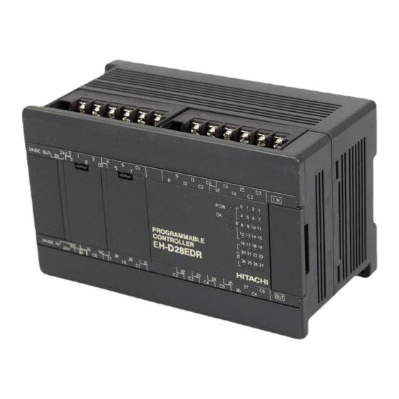
Chapter 2 Specifications 2.18.2 Terminal layout and wiring (1) 64-point type [ EH-A64EDR (AC power type) ] *: For the DC input, both sink and source types are available. It is possible to reverse the polarity of 24 V DC. Input power 24VDC Input Output... - Page 39 Chapter 2 Specifications (2) 28-point type [EH-A28EDR (AC power type)] *: For the DC input, both sink and source types are available. It is possible to reverse the polarity of 24 V DC. Input power 24V DC Power supply Power for load (Relay output) 100 to 240V AC 5 to 30V DC, 5 to 250V AC [EH-D28EDR (DC power type)] Input wiring is same as EH-A28EDR.
- Page 40 Chapter 2 Specifications [EH-D28EDTP (DC power type)] Input Power 24V DC Input Output Power supply Power for load 24V DC 12/24V DC [EH-D28EDT (DC power type)] Input wiring is same as EH-D28EDTP. Output Power supply Power for load 24V DC 12/24V DC 2 –...
- Page 41 Chapter 2 Specifications (3) 16-point type [ EH-D16ED (DC power type) ] *: For the DC input, both sink and source types are available. It is possible to reverse the polarity of 24 V DC. Input power 24V DC Power supply 24V DC [ EH-D16ER (DC power type) ] Power for load (Relay output) 5 to 30V DC, 5 to 250V AC...
- Page 42 Chapter 2 Specifications (4) 14-point type [ EH-A14EDR (AC power type) ] *: For the DC input, both sink and source types are available. It is possible to reverse the polarity of 24 V DC. Input Power 24V DC Input Output Power supply Power for load (Relay output)
- Page 43 Chapter 2 Specifications (5) 8-point type [ EH-D8ED (DC power type) ] *: For the DC input, both sink and source types are available. It is possible to reverse the polarity of 24 V DC. Input power 24V DC Power supply 24V DC [ EH-D8ER (DC power type) ] Power for load (Relay output) 5 to 30V DC, 5 to 250V AC...
- Page 44 Chapter 2 Specifications [ EH-D8ET (DC power type) ] Power for load 12/24V DC Power supply 24V DC [ EH-D8EDR (DC power type) ] *: For the DC input, both sink and source types are available. It is possible to reverse the polarity of 24 V DC. Input power 24V DC Input...
- Page 45 Chapter 2 Specifications (6) Analog expansion unit [ EH-A6EAN (AC power type) ] Voltage input and output (Input and output are configured separately.) Ch.1 Ch.2 Ch.3 Ch.4 Input voltage 0 to 10V IN1+ IN2- IN2JP IN3+ IN4- IN4JP IN1- IN1JP IN2+ IN3- IN3JP...
- Page 46 Chapter 2 Specifications (7) RTD expansion unit [ EH-A6ERTD (AC power type) ] Example of RTD input and Voltage output Input temperature Pt100 -100 to +600 C IN1B IN2A IN2b IN3B IN4A IN4b IN1A IN1b IN2B IN3A IN3b IN4B Power supply 100 to 240VAC Output voltage 0 to +10V...
- Page 47 Chapter 2 Specifications (8) Thermocouple expansion unit [ EH-D6ETC (DC power type) ] Current output Thermocouple Sensor -200 to +1700 C Cold junction IN1+ IN2+ IN3+ IN4+ IN1- IN2- IN3- IN4- Output current 0 to 20mA Power supply 24VDC Voltage output Output voltage 0 to +10V [ EH-D4ETC (DC power type) ]...
-
Page 48: External Dimensions
Chapter 2 Specifications 2.19 External dimensions Unit: mm [ 64-point basic / expansion unit ] [ 20-point / 40-point basic unit and 28-point expansion unit ] [ 16-point / 14-point / 8-point and Analog / RTD / Thermocouple expansion unit ] 2 –... -
Page 49: Option Board
Chapter 2 Specifications 2.20 Option board 2.20.1 OBV-NES Name and function of each part Type OBV-NES Weight 15g (0.03 lb.) (2) Communication LED (3) Basic unit connector (bottom) (1) Communication port (4) Terminating resistance switch (bottom) Item Description Communication port Communication port supports IEC programming function supporting Modbus-RTU master/slave and general purpose communication. -
Page 50: Obv-485A
Chapter 2 Specifications 2.20.2 OBV-485A Name and function of each part Type OBV-485A Weight 20g (0.04 lb.) (2) Communication LED (4) Analog input terminal (3) Basic unit connector (bottom) (1) Communication port (5) Terminating resistance switch (bottom) Item Description Communication port supports IEC programming function supporting Modbus-RTU master/slave Communication port and general purpose communication. -
Page 51: Obv-485Tai/485Tao/Aio
Chapter 2 Specifications 2.20.3 OBV-485TAI/485TAO/AIO Name and function of each part Type OBV-485TAI/485TAO/AIO Weight 20g (0.04 lb.) (3) LED (1) Communication port or Analog input terminal (4) Connector to basic unit (Back side) (2) Analog input terminal or Analog output terminal Type Item Description... - Page 52 Chapter 2 Specifications Analog input specifications ( OBV-485A/485TAI/AIO Item Specifications No. of input 2 Channel Input range 0 to 10V (10.24V max.) Accuracy 1 % or less (of full-scale value) Resolution 10 bits AD conversion time 8ms / 2 Channel External wiring 2-core shield cable (3 m or less) Approx.
-
Page 53: Obv-Aig/Aiog/Rtd
Chapter 2 Specifications 2.20.4 OBV-AIG/AIOG/RTD Part names and functions Model name OBV-AIG / AIOG / RTD Weight 20g (0.04 lb.) [Back side] [Upper side] (3) DIP switches (1) Analog input terminal or (Except OBV-RTD) RTD input terminal (4) Connector to basic unit (2) Analog input terminal or Analog output terminal or... - Page 54 Chapter 2 Specifications Setting of the DIP switches Voltage / current mode can be set for each channel of analog I/O. Be sure to make setting of DIP switches and setting by the programming tool the same. In the case of not equal, the option board does not work properly. Setting items Switch Setting...
- Page 55 Chapter 2 Specifications Terminal layout (1) OBV-AIG terminal layout Terminal layout Signal Function Internal circuit IN1+ CH1 input + 120k 1) IN1+ SW1-1 IN1- CH1 input - Voltage 2) IN1- [Analog input] IN2+ CH2 input + 3) IN2+ ...
- Page 56 Chapter 2 Specifications (3) OBV-RTD terminal layout (3-wire) Terminal layout Signal Function Internal circuit CH1 input A 0.49 mA Pt100 1) 1A CH1 input - [RTD input] 2) 1b CH1 input B 3) 1B 4) NC Pt100 CH3 input A 5) 3A 6) 3b CH3 input -...
- Page 57 Chapter 2 Specifications Analog input specifications (OBV-AIG / AIOG) Item Specifications Model name OBV-AIG OBV-AIOG Number of channel Single-ended 4 channels Single-ended 2 channels Voltage input 0 to 10 V (Max. 10.24 V) Input range Current input 0 to 20 mA (Max. 20.48 mA) Voltage input 0 to 10 V: 0 to 4,000 / 0 to 16,000 Resolution...
-
Page 58: Communication Cable Connection
Chapter 2 Specifications 2.20.5 Communication cable connection The following figure shows the communication cable connection example. Be sure to use shielded twisted pair cable. [OBV-NES] MICRO-EHV+ MICRO-EHV+ MICRO-EHV+ OBV-NES OBV-NES OBV-NES Terminal [5] SP [5] SP [5] SP resistor [6] SN [6] SN [6] SN 120Ω... -
Page 59: Installation Of Option Board
Chapter 2 Specifications Use the built-in termination resistors (120Ω) depending on the usage environment and the cable type. If the communication is unstable, perform the followings. (1) Instead of the built-in termination resistor, attach termination resistors that match the characteristic impedance of the cable at both ends of the communication cable. -
Page 60: Accessories
Chapter 2 Specifications 2.21 Accessories 2.21.1 Expansion cable EH-MCB01 / 05 / 10 Features Type Approx. 210 (0.46) / 240 (0.53)/ 300 g Weight (0.66 lb.) 0.1 (0.33) / 0.5 (1.64)/ 1.0m (3.28 ft.) EH - MCB01 Length * EH-MCB01 is an accessory of expansion units. EH - MCB05/10 Function Connects the basic unit and the expansion unit or the expansion unit to each other. -
Page 61: Installation
Chapter 3 Programming Installation 3.1.1 System Requirements Recommended CPU : Pentium 1 GHz or higher Memory : 1 GB or more RAM Free disc space : 3 GB or more Resolution : 1024 x 768 (XGA) or higher Operating System : Windows XP SP3 / Vista / 7 (32 / 64 bit) / 8 / 8.1 / 10 3.1.2 Installation of HX-CODESYS Before installation, shut down all other Windows... - Page 62 Chapter 3 Programming It takes about 30 minutes to 2 hours to finish installation depending on the specifications of PC. N o t e Several Microsoft components are necessary to be installed for HX-CODESYS. If they are not installed in your PC, the installation of HX-CODESYS stops and a dialog appears.
-
Page 63: Installation Of Usb Driver
Chapter 3 Programming 3.1.3 Installation of USB driver 1. Plug in USB cable to CPU module. USB cable is not included in the product. To prevent communication error by noise, prepare USB cable with ferrite core. 2. Popup window appears at right-bottom of screen. Click the popup window. 3. - Page 64 Chapter 3 Programming 5. Enter the below path and click [Browse] to install the USB driver. 6. Click [Install]. 7. If the installation is finished successfully, below dialog appears. 3 – 4...
-
Page 65: Startup
Chapter 3 Programming Startup Choose [Start menu]-[All programs]-[HX-CODESYS]-[HX-CODESYS], then the start page is displayed. Click icon or choose [File]-[New Project...] to create a new project file. Then New Project dialog box appears. Choose [Standard project], enter new file name, specify location and click [OK]. 3 –... - Page 66 Chapter 3 Programming Choose CPU type and programming language and click [OK]. Available languages are as follows. Continuous Function Chart (CFC) Function Block Diagram (FBD) Instruction List (IL) Ladder Logic Diagram (LD) Sequential Function Chart (SFC) Structured Text (ST) Initial layout of the project is shown like this. Variable declaration Editor Devices...
-
Page 67: I/O Configuration
Chapter 3 Programming I/O Configuration 3.3.1 Scan For Devices for expansion units If expansion units are used, actual I/O configuration can be read out from connected CPU. This operation is not necessary if only CPU unit is used. Right click on “Expansion units” and choose “Scan For Devices...”. Then “Scan Devices” dialog appears. Click “Copy all devices to project”. -
Page 68: Eh-A64Edr
Chapter 3 Programming MICRO-EHV+ allows to expand up to 4 expansion units. Configure expansion unit according to the list below. Model names Device Names MICRO EXP. 64 Digital I/O EH-A64EDR EH-D64E** EH-A28EDR MICRO EXP. 8-28 Digital I/O EH-D28E** EH-D16E** EH-A14EDR EH-D14E** EH-D8E** EH-A6EAN... -
Page 69: Option Board
Chapter 3 Programming 3.3.2 Option board Choose “Add Device” to configure option board. Configure option board according to the list below. Model names Device Names OBV-NES Option_Board OBV-485A OBV-485TAI OBV-485TAO OBV-AIO OBV-AIG Option_Board OBV-AIG OBV-AIOG Option_Board OBV-AIOG OBV-RTD Option_Board OBV-RTD 3 –... -
Page 70: Update Device
Chapter 3 Programming 3.3.3 Update Device Although device (CPU) type is required to set when creating new project, it can be changed later. Right mouse click on the device and choose “Update Device”. Then “Update Device” window appears. Choose one of the devices and click [Update Device] button. If necessary, click at “Display all versions (for experts only)”... -
Page 71: I/O Address
Chapter 3 Programming 3.3.4 I/O address I/O addresses and variable names can be linked in two different ways: Global variable or Local variable as below. [Global variable] Double click on plugged I/O module or right click and choose “Edit Object”. I/O Mapping window appears as below. - Page 72 Chapter 3 Programming Input any variable names in the field “Variable” according to your system. After defining variable names, they will be automatically listed up when it is used in all POU with assist of auto-complete. If a variable is already used (declared) in POU or global variable list, it can be taken by clicking icon in I/O mapping window.
- Page 73 Chapter 3 Programming [Local variable] Local variables are defined in each POU and valid only in the POU. If new variable name is used in the first time, Auto Declare window will appear as below. In this window, there is an input field “Address”.
- Page 74 Chapter 3 Programming I/O address example of 64 points basic / expansion unit [ Input ] [ Output ] Bit number BOOL LWORD Bit number BOOL DWORD Bit 0 %IX7.0 %IL0 Bit 0 %QX3.0 %QD0 Bit 1 %IX7.1 Bit 1 %QX3.1 Bit 2 %IX7.2...
-
Page 75: I/O-Update
Chapter 3 Programming I/O-update Input data is read at the beginning of a task and output data is written at the end of a task. I/O-update settings are configured in “PLC settings” in Device tab. Be noted that only used I/Os in program are updated. Update IO while in stop If this option is activated (default), the values of the input and output channels get also updated when the PLC is stopped. -
Page 76: Pou And Task
Chapter 3 Programming POU and task One application has at least one POU and one task as shown below. POU stands for Program Organization Unit. This can be assumed as a paper to create your program. Only one programming language can be used in one POU. If you need another language, add POU by right click on “Application”... - Page 77 Chapter 3 Programming Task POU does not have information how to execute POU. This information is handled by task. Put priority, choose type of task and add or remove POU accordingly. Priority (0-3) 0 is the highest priority, 3 is the lowest. Cyclic task The task will be processed cyclic according to the time definition given in the field “Interval”.
-
Page 78: Variables
Chapter 3 Programming Variables 3.6.1 Data memory In HX-CODESYS programming, external I/Os and data memory (internal registers) are handled as variable names instead of direct I/O addresses, such like “A1_switch”. If new variable name is used, below Auto Declare window appears. -
Page 79: Marker Memory
Chapter 3 Programming 3.6.2 Marker memory Normally users do not have to take care about internal address of data memory however, if needed, the marker memory is useful. The address of marker memory is %M. For example, DWORD data dwTest, WORD data wTest_H and wTest_L are declared in the address %MD10, %MW20 and %MW21. -
Page 80: Available Characters For Variable Names
Chapter 3 Programming 3.6.3 Available characters for variable names Available characters for variable names are only alphabet a to z, A to Z and number 0 to 9 and _ (underscore). The first character must not be numeric characters. Several words like BOOL, WORD, IF, FOR etc. are reserved. Supported characters Types Supported... -
Page 81: Data Types
Chapter 3 Programming 3.6.5 Data types HX-CODESYS supports below data types. Data types Name Size Range BOOL Boolean 0 or 1 SINT Short integer -128 to 127 USINT Unsigned short integer 0 to 255 BYTE Bit string of length 8 0 to 255 (16#00 to 16#FF) Integer -32,768 to 32,767... -
Page 82: Local Variable
Chapter 3 Programming 3.6.6 Local variable If new variable name is used in POU, Auto Declare window appears as below. If the field “Address” is remained as empty, this variable will be assigned in a certain memory area of CPU. Click [OK] button, this variable is registered in declaration part of POU as below. -
Page 83: Global Variable
Chapter 3 Programming 3.6.7 Global variable If variables need to be commonly used in all POUs, “Global Variable List” must be created by right click on Application as below. If new variable name is used in POU, Auto Declare window appears as shown in local variables. Choose “VAR_GLOBAL”... -
Page 84: Configuration
Chapter 3 Programming Configuration Open device window and set CPU’s parameters in Configuration tab. Parameter Description When requesting to change the Ethernet port related parameters, be sure to set “Yes” IP Address in “Change IP information”, otherwise parameters are not downloaded. Do not forget Subnet Mask to set back to “No”... -
Page 85: Communication Settings
Chapter 3 Programming Communication settings How to configure Double click on “Device (MV-xxx)” or right click and choose “Edit Object”. “Device” window will appear as below. Choose “Communication Settings” tab and click “Add gateway”. “Gateway” window will appear. Click “OK”. Sine the communication type between HX-CODESYS and gateway (in PC) is TCP/IP, displayed driver name is “TCP/IP”... - Page 86 Chapter 3 Programming The gateway is displayed as below. Click “Scan network” to search available device in the network. If CPU is found, it is displayed as below. Click “Set active path” to choose as the target device. Target CPU is activated. Communication settings are completed. CPU name Target ID MV-*64**...
-
Page 87: Programming
Chapter 3 Programming Programming Ladder programming Basic ladder programming is shown below as a first step. Please refer to online-help of HX-CODESYS for further information about programming. Several ways are available to add contact or coil to POU as below. Contact - Drag from ToolBox to [Start here]. - Page 88 Chapter 3 Programming Parallel contact across several contacts Click several contacts with shift key and choose [Insert Contact Parallel] in right-mouse click menu or press [Ctrl + R] key. 3 – 28...
-
Page 89: Login
Chapter 3 Programming 3.10 Login Login After programming, click or choose [Build] in Build menu. If compiling fails, error information is shown at “Description” field as follows. Double click the message to jump to the part to be corrected. N o t e If unknown message appears, it is recommended to [Clean all] in Build menu. - Page 90 Chapter 3 Programming When logging in successfully, green circle icon is displayed at [Device]. If connected expansion units are matched with configured ones, green icon is displayed at each expansion unit also. If any mounted I/O module is mismatched, red triangle icon is displayed at mismatched module as below (right side). Online monitoring After login, actual status of variables are shown as below.
- Page 91 Chapter 3 Programming Write values Prepare values for the variables by clicking at [Prepared value] or double clicking at ladder symbols. Choose the menu [Debug]-[Write values] or press [Ctrl + F7]. The prepared values will be transferred to PLC. Online change To change your program in running CPU (online change), you have to logout at first.
-
Page 92: Boot Application
Chapter 3 Programming 3.11 Boot application The basic overview of downloading is shown as below picture. Be noted that an application (compiled user program) is downloaded to volatile RAM memory of the CPU, which means the application is lost when power is removed. If your application needs to be saved in non-volatile FLASH memory, choose [Create boot application] in Online menu while Login. -
Page 93: Source Download / Upload
Chapter 3 Programming 3.12 Source Download / Upload Besides boot application, source file can be saved in the CPU, which enables you to upload original program file from PLC even if you don’t have it in your PC. Some extra files can be added to source file as below. Choose according to your necessity. -
Page 94: Run / Stop / Reset
Stop switch definition Definition of stop position of run/stop switch can be configured as “Stop” or “Reset warm” in CPU configuration. Default setting is “Reset warm” since it is almost same behavior of original “Stop” for existing Hitachi PLC. 3 – 34... -
Page 95: Global Network Variables
Chapter 3 Programming 3.14 Global network variables Any variables can be listed in global network variable list, which are sent to all other CPUs in the network with broadcast address of UDP/IP. Global net work variable function is available only in professional setting. Refer to section 3.2 Start up how to change the environment setting. - Page 96 Chapter 3 Programming In this sample, one global variable “test_var” is defined and one-line program is written in POU as below. [ CPU “Receive” ] The next step is configuration for receiving CPU. Right click on “Application” of Receive-CPU and choose “Network Variable List (Receiver)...”...
- Page 97 Chapter 3 Programming Login Set the communication path for Send-CPU and login (download application). After logout, right click on “Application” of Receive-CPU and choose “Set Active Application”. Set the communication path for Receive-CPU and login (download application). Active Active You can see the variable “test_var” is counting up in the global network variable list in the Receive-CPU. Counting up N o t e ...
-
Page 98: Modbus-Tcp/Rtu
Chapter 3 Programming 3.15 Modbus-TCP/RTU 3.15.1 Introduction Supported function codes are shown in the below table. Modbus-RTU Master Modbus-RTU Slave Function code Modbus-TCP Master Modbus-TCP Slave 0x01 Read Coils 0x02 Read Discrete Inputs 0x03 Read Holding Registers 0x04 Read Input Registers 0x05 Write Single Coil 0x06... -
Page 99: Modbus-Tcp Master (Client)
Chapter 3 Programming 3.15.2 Modbus-TCP master (client) Modbus-TCP master function is supported by CPU ROM VER.3.5.3.42 or higher version. Right click on “Device” and choose “Add Device...”. “Add Device” window appears. Click “Ethernet” and [Add Device] button. With “Add device” window opened, click “Ethernet” in the device tree. Then available devices will be shown in the “Add Device”... - Page 100 Chapter 3 Programming Be sure to configure all slave modules to be controlled. Function codes to be sent are configured in each slave. Double click a slave unit to open configuration window. Set IP address, response timeout and port number as below. Unit-ID is used when a Modbus-gateway (Ethenet to serial) device is used.
- Page 101 Chapter 3 Programming Configure each parameter as below. If the Trigger setting is “Rising edge”, trigger variable (BOOL) will be automatically assigned in %QX address. Data of Modbus will be assigned to %IW or %QW as seen in “ModbusTCPSlave I/O Mapping” tab. Read data from slave is assigned to input area (%IW) and data to be written to slave is assigned to output area (%QW).
-
Page 102: Modbus-Tcp Slave (Server)
Chapter 3 Programming 3.15.3 Modbus-TCP slave (server) Right click on “Device” and choose “Add Device...”. “Add Device” window appears. Click “Ethernet” and [Add Device] button. Right click on “Ethernet” and choose “Add Device...”. Click “Modbus TCP Slave Device” in the “Add Device” window and [Add Device] button. -
Page 103: Modbus-Rtu Master
Chapter 3 Programming 3.15.4 Modbus-RTU master Right click on “Device” and choose “Add Device...”. “Add Device” window appears. Click “Modbus COM” and [Add Device] button. With “Add device” window opened, click “Modbus_COM” in the device tree. Then available devices will be shown in the “Add Device”... - Page 104 Chapter 3 Programming With “Add device” window opened, click “Modbus_Master_COM_Port” in the device tree. Then “Modbus Slave, COM Port” is shown in the “Add Device” window. Click “Modbus Slave, COM Port” and [Add Device] button according to your Modbus system configuration. e.g. if 3 slaves are to be controlled, add 3 times of slave devices. Be sure to configure all slave modules to be controlled.
- Page 105 Chapter 3 Programming Open “Modbus Slave Channel” tab and click “Add Channel...” to add function codes. Configure each parameter as below. If the Trigger setting is “Rising edge”, trigger variable (BOOL) will be automatically assigned in %QX address. Data of Modbus will be assigned to %IW or %QW as seen in “ModbusGenericSerialMaster I/O Mapping” tab. Read data from slave is assigned to input area (%IW) and data to be written to slave is assigned to output area (%QW) 3 –...
-
Page 106: Modbus-Rtu Slave
Chapter 3 Programming 3.15.5 Modbus-RTU slave Add “Modbus_COM” same as the setting of Modbus-RTU master. Right click on “Modbus_COM” and choose “Add Device...”. Click “Modbus Serial Device” in the “Add Device” window and [Add Device] button. Configure each parameter as below. According to the size of “Holding Registers” and “Input Registers”, data area will be assigned as seen in “Modbus Serial Device I/O Mapping”... -
Page 107: Ethercat Master
Chapter 3 Programming 3.16 EtherCAT master EtherCAT master function is supported by CPU ROM VER.3.5.3.42 or higher version. 3.16.1 Configuration Right click on “Device” and “Add Device...”. “Add Device” window appears. Click “EtherCAT Master” and [Add Device] button. With “Add device” window opened, click “EtherCAT_Master” in the device tree. Then available devices will be shown in the “Add Device”... -
Page 108: Online Settings
Chapter 3 Programming 3.16.2 Online settings Open communication to CPU according to the section 3.8 Communication settings. Double click on EtherCAT_Master or right click and choose “Edit Object” to open EtherCAT_Master window. Click “Browse” button. If active path is correctly set, the CPU is detected in “Select Network Adapter” dialog box as below. Click [OK] to set the MAC address of the CPU in “Source Address (MAC)”... -
Page 109: Ethernet Speed
Chapter 3 Programming 3.16.3 Ethernet speed Since EtherCAT works in 100Mbps only, default setting of Ethernet speed is “Auto Negotiation”. Normally it should work, but if not, set “100Mbps/Full Duplex” in “Ethernet port Link speed / Duplex mode” and set “Yes” in “Change IP information”... - Page 110 Chapter 3 Programming Cycle (interval) time of EtherCAT master Recommended : Declaration in EtherCAT I/O mapping Not recommended : Declaration in POU and referred from EtherCAT I/O mapping Following information is based on our slave controller EH-IOCA. Declaration in EtherCAT I/O mapping is about two times faster than declaration in POU. ...
-
Page 111: Programming
Chapter 3 Programming 3.16.5 Programming I/O addresses of slaves are displayed in “EtherCAT I/O Mapping” tab as below. Enter any variable names in this table and create your program as same way as other standard I/Os. N o t e When PLC is powered up with RUN switch position in RUN, I/O refresh of EtherCAT slaves starts about a few second (depending on slave units) after I/O refresh of standard I/O started because of configuration between EtherCAT master and all slaves as below. -
Page 112: Wiring
Chapter 3 Programming 3.16.6 Wiring (1) Cable Use category 5 or higher STP (Shielded Twisted Pair) cable. (2) Switch (Hub) Standard switch (hub) is not allowed to use in EtherCAT network. If necessary, use a special device like EtherCAT hub (CU1128) sold by Beckhoff. N o t e Please note that using various Ethernet based communication (EtherCAT, Modbus-TCP, NVL, Gateway) at the same time will limit the communication performance. - Page 113 Chapter 3 Programming (2) Local variables are defined in a POU and referred from EtherCAT I/O mapping as below. (3) Direct address in smaller data type than bit channels Slave units of 16/32/64-bit channels are used and direct address is used in smaller data type than bit channels. [Example] In case of 16-bit channel (UINT) slave, the direct address of UINT is %QW2.
-
Page 114: High Speed Counter
Chapter 3 Programming 3.17 High speed counter DC inputs of MICRO-EHV+ are configurable for 32-bit high speed counters. Each channel has two preset values set by special function block. If the counter value exceeds the preset value, then event task will be executed immediately, which leads POU (FUNCTION) under the task called accordingly. Desired program can be written in this FUNCTION. - Page 115 Chapter 3 Programming Configuration of 2-phase counter Right click on “2-phase counters” and choose “Add Device…”. Then “Add Device” window appears. Click 2Phase counter ch1 or ch3 and [Add Device] button. Double click on “_2Phase_counter_chx…” or right click and choose “Edit Object”. 2-phase counter configuration window appears.
- Page 116 Chapter 3 Programming Configuration Parameter Descriptions Choices Default Counter mode 4 different counter modes are supported as 2-phase 4-edge 2-phase 4-edge shown below. 2-phase Pulse + Direction CW/CCW Marker (Z) input When Marker (Z) input is enabled and Disable Disable rising/falling edge of the input is detected, Enable the counter value is reset (0).
- Page 117 Chapter 3 Programming Configuration of single counter Right click on “Single counters” and choose “Add Device…”. Then “Add Device” window appears. Click Single counter chx and [Add Device] button. Double click on “Single_counter_chx…” or right click and choose “Edit Object”. Single counter Mapping window appears.
- Page 118 Chapter 3 Programming Mapping Name Type Descriptions Enable Output (%QX) BOOL TRUE: Counter is enabled. FALSE: Counter is disabled. Direction Output (%QX) BOOL TRUE: Down counter FALSE: Up counter Counter Input (%ID) DWORD Counter value is increased or decreased with every rising edge and stored in this register.
- Page 119 Chapter 3 Programming Start/Stop Counter is started or stopped by the variable (%QX) configured in “Enable” in configuration window. While this variable is TRUE, counter is enabled. No function block is required to start or stop. Read counter value CPU ROM VER.3.5.3.41 or older Counter value is stored automatically in the variable (%ID) configured in “Counter”...
- Page 120 Chapter 3 Programming MV_CU_Read FB name Description MV_CU_Read This function block is to read counter value for specified channel of counter Name Type Descriptions xExecute BOOL A rising edge starts the execution. byChannel BYTE Channel number (2-phase counter: 1or 3, Single counter: 1 to 5) xDone BOOL Execution done successfully...
- Page 121 Chapter 3 Programming Preset value If the counter value exceeds the preset value 1 or 2, then corresponding event task will be executed immediately, which leads POU (FUNCTION) under the task called accordingly. Desired program can be written in this FUNCTION.
- Page 122 Chapter 3 Programming FUNCTION called (EventPrm.byChannelIndex=2) FUNCTION called (EventPrm.byChannelIndex=1) FUNCTION called (EventPrm.byChannelIndex=1) Preset2 Preset1 Counter Marker If counter value exceeds preset value 1 or 2, then program execution is interrupted and corresponding FUNCTION is called. After that, program execution returns back to the original position. Each counter has two different preset values, but the same FUNCTION is called.
-
Page 123: Interrupt Input
Chapter 3 Programming 3.18 Interrupt input DC inputs of MICRO-EHV+ are configurable for interrupt inputs. If rising or falling edge is detected, then event task will be executed immediately, which leads POU (FUNCTION) under the task called accordingly. Desired program can be written in this FUNCTION. Available I/O addresses of high speed counter and interrupt input are listed as below. - Page 124 Chapter 3 Programming Configuration Right click on “Interrupts” and choose “Add Device…”. Then “Add Device” window appears. Click Interrupt chx and [Add Device] button. Double click on “Interrupt_chx…” or right click and choose “Edit Object”. Interrupt configuration window appears. Configuration Parameter Descriptions Choices...
- Page 125 Chapter 3 Programming Event task If rising or falling edge is detected, then corresponding event task will be executed immediately, which leads POU (FUNCTION) under the task called accordingly. Desired program can be written in this FUNCTION. Event task is configured as follows.
-
Page 126: Pulse Train Outputs
Chapter 3 Programming 3.19 Pulse Train Outputs DC outputs of MICRO-EHV+ are configurable for pulse train output. This can be used to control stepper motors. Two different controls, position control and speed control, are supported. The both controls have ramp feature. Position control Position and speed are specified as number of pulses and frequency. - Page 127 Chapter 3 Programming Double click on “Pulse_output_chx…” or right click and choose “Edit Object”. Pulse output configuration window appears. Pulse output has Configuration tab and Mapping tab as below. Configuration Parameter Descriptions Choices Default Direction Additional output besides pulse train output can be Disable Disable used to define direction.
- Page 128 Chapter 3 Programming Dedicated library must be added to the project for pulse train operations. Double click on “Library Manager” or right click and choose “Edit Object”. Library Manager window appears. Click “Add library” and choose “CmpHIESLib_MV”. CmpHIESLib library is added in the project. 3 –...
- Page 129 Chapter 3 Programming MV_PLS_Start FB name Description MV_PLS_Start This function block is to output pulse train for position control. Pulse train stops after specified number of pulses have been completed. Name Type Descriptions xExecute BOOL A rising edge starts the execution. byChannel BYTE Channel number (1 to 3)
- Page 130 Chapter 3 Programming MV_PLS_Write FB name Description MV_PLS_Write This function block is to overwrite current position data Name Type Descriptions xExecute BOOL A rising edge starts the execution. byChannel BYTE Channel number (1 to 3) dwPosition DWORD Position data to write 0 to 4,294,967,295 (direction disabled) -2,147,483,648 to 2,147,483,647 (direction enabled) xDone...
- Page 131 Chapter 3 Programming MV_PLS_Changespeed FB name Description MV_PLS_Changespeed This function block is to change frequency of pulse train for speed control. This function block works only when pulse train is in operation by MV_PLS_speed. Name Type Descriptions xExecute BOOL A rising edge starts the execution. byChannel BYTE Channel number (1 to 3)
-
Page 132: Pwm Outputs
Chapter 3 Programming 3.20 PWM Outputs DC outputs of MICRO-EHV+ are configurable for PWM (Pulse-Width Modulation) output. This can be used to control DC and stepper motors. Available I/O addresses of pulse train output and PWM output are listed as below. bit 0 bit 1 bit 2... - Page 133 Chapter 3 Programming Operations PWM output can be controlled by function blocks as below. Operations Variable or FB Name Start PWM output Function block MV_PWM_Start Stop PWM output Function block MV_PWM_Stop MV_PWM_Start FB name Description MV_PWM_Start This function block is to start PWM output. Name Type Descriptions...
-
Page 134: Option Board
Chapter 3 Programming 3.21 Option board 3.21.1 Supported function Option board supports the following communication functions and analog input/output. Function OBV- OBV- OBV- OBV- OBV- OBV- OBV- OBV- 485A 485TAI 485TAO AIOG RS-485 Modbus-RTU master Modbus-RTU slave General purpose com. Analog input 2 ch. -
Page 135: Port Number Setting
Chapter 3 Programming 3.21.2 Port number setting The port number setting of option board is fixed to “COM2” (“COM1” is reserved for CPU local port). CPU port “COM1” (fixed) Option board port “COM2” (fixed) 3.21.3 Analog input/output setting Double click on “Option_Board” or right click and choose “Edit Object.” Option_Board Configuration window appears. - Page 136 Chapter 3 Programming [ Option Board OBV-AIOG ] [ Option Board OBV-RTD ] Data of Analog input/output will be assigned to %IW/%QW as seen in “Option_Board I/O Mapping” tab. Analog outputs have been available since the option board device version 3.5.3.41 or newer and supported by CPU ROM VER.
-
Page 137: Modbus-Rtu Communication
Chapter 3 Programming 3.21.4 Modbus-RTU communication Modbus operation is same as CPU port. Refer to section 3.15.4 and 3.15.5 for further information. 3.21.5 General purpose communication Besides Modbus-RTU communication, option board supports general purpose communication same as CPU port. Add “SysCom” library by clicking “Add library” on Library manager. Only the difference from CPU port is COM port number. -
Page 138: Usb Program Transfer
Chapter 3 Programming 3.22 USB program transfer This function is supported by MICRO-EHV+ CPU ROM VER.3.5.3.41 or newer. User program can be downloaded, uploaded or verified according to dip switch settings as below. USB LED Dip switch Function Action when USB LED Download (USBPLC) Power up... -
Page 139: Upload From Plc To Usb
Chapter 3 Programming 3.22.2 Upload from PLC to USB Application program and source file, if available, is uploaded from FLASH memory in the PLC to USB memory. Follow the steps as below. (1) Set the dip switch 2-ON, 1,3,4-OFF. (2) Plug the USB memory to the USB connector of MICRO-EHV+. (3) Application.app and Application.crc will be uploaded from PLC to USB. -
Page 140: Usb Data Logging (File System)
Chapter 3 Programming 3.23 USB data logging (File system) This function is supported by MICRO-EHV+ CPU ROM VER.3.5.3.41 or newer. This function works only when USB memory is plugged in MICRO-EHV+. Since USB memory supports file system, the library CAA File is available with USB memory. One of the useful functions of CAA File is data logging. - Page 141 Chapter 3 Programming Program 3 – 81...
- Page 142 Chapter 3 Programming N o t e Not all the function blocks of CAA File libraries are supported as below. Function block Supported Function block Supported Close Read Copy Rename Y *1*2 Delete SetPos Write Flush DirClose GetAttribute DirCreate (incl. sysDirCreate) GetPos DirList GetSize...
-
Page 143: Web Visualization
Chapter 3 Programming 3.24 Web visualization This function is supported by MICRO-EHV+ CPU ROM VER.3.5.3.41 or newer. This function works only when USB memory is plugged in MICRO-EHV+. Besides standard visualization, MICRO-EHV+ supports Web visualization. Once visualization application is created and downloaded together with user program, PLC works as a web server and any web browser can access, read and write variables in the PLC. - Page 144 Chapter 3 Programming N o t e Web browser must support HTML5 with JavaScript enabled. Webvisualization works only when PLC is in RUN status. Local I/O (external I/O) is not updated in web visualization and standard visualization. If it is necessary to read or write local I/O directly, use additional variables in web visualization and copy them to/from local I/O in the IEC program.
-
Page 145: Libraries
3.25.1 How to install In order to read/write MICRO-EHV+ series PLC’s specific information, the following libraries are available. Add necessary CmpHIESLib_MV by choosing “Add library” as shown below. CmpHIESLib_MV is Hitachi-IES’s special library including; 2 Phase counters Single counters Interrupts... -
Page 146: Real Time Clock
Chapter 3 Programming 3.25.2 Real time clock Add “CAA Real Time Clock Extern” library by clicking “Add library” on Library manager. In the CAA DTUtil Extern libraries, GeTimeZoneInformation and SetTimeZoneInformation are not supported..Supported ...Supported ...Not supported ...Not supported Following example is in FBD language. Choose [Insert Box] in [FBD/LD/IL] menu and GetDateAndTime or SetDateAndTime as shown below. -
Page 147: Serial Communication
Chapter 3 Programming Declare instance of the function blocks and necessary variables as below. By rising edge of xExecute bit of SetDateAndTime, data in dtDateAndTime is written to the RTC device. By rising edge of xExecute bit of GetDateAndTime, current date and time is read out to the variable connected to dtDateAndTime as shown below. - Page 148 Chapter 3 Programming It is recommended to use ST language for serial communication settings since it is more flexible..COM1 ...Non parity ...1 stop bit ...baudrate 19,200bps ...buffer size 100 bytes ...Timeout 10ms ...8 bit / frame ...Connect 02 + “123” ...Connect 02 “123”...
-
Page 149: Troubleshooting
Chapter 3 Programming 3.26 Troubleshooting 3.26.1 Error indication MICRO-EHV+ indicates the error by the lighting pattern (ON / blink / OFF) of OK LED. If two or more errors are detected at the same time, smaller error code has higher priority to be displayed. If error is detected, read the description following countermeasures depending on error level. - Page 150 Chapter 3 Programming Err. Error name Description Applica- code [Detected when] system tion Misalignment / Microprocessor has detected an exception Stop Illegal instruction / processing in application. Privileged instruction [Always] Retain identity Retain data memory is undefined status due Stop mismatch to battery empty.
- Page 151 Chapter 3 Programming (*1) OK LED is not lighting up If error code 13 is detected, OK LED is not lighting up and it is not possible to communicate with HX-CODESYS because the system program or boot project is failure. If cycling power does not solve the problem, boot project could be failure.
- Page 152 Chapter 3 Programming Error libraries As for warnings (error code 70 to 78), special libraries called “CmpHitachiErrors_MV” are available as below. Use them in your application program if necessary. If it is not registered in your library repository, install CmpHitachiErrors_MV.library by choosing [Tools]-[Install library...]. Error Libraries (CmpHitachiErrors_MV.library) Input...
-
Page 153: Version
Chapter 3 Programming 3.27 Version Firmware version (Target-Version) of your CPU is monitored in communication settings of Device as below. The key functions supported by MICRO-EHV+ are listed below. CPU ROM version Category Function 3.5.3.41 3.5.3.42/43 3.5.3.44 3.5.3.40 Communication Modbus-TCP Master Modbus-TCP Slave Modbus-RTU Master Modbus-RTU Slave... -
Page 154: Package Manager
Chapter 3 Programming 3.28 Package Manager The runtime version of MICRO-EHV is V3.5.3.40. Corresponded CODESYS version is V3.5 SP3 Patch4. This version contains right version of library files for the runtime 3.5.3.40. If newer version of CODESYS is used, several libraries are updated, which could result in compiling error. -
Page 155: Installation
Chapter 4 Installation For use in safety, avoid installing the PLC in the following locations. - Excessive dusts, salty air, and/or conductive materials (iron powder, etc.) - Direct sunlight - Temperature less than 0C or more than 55C - Dew condensation - Humidity less than 5% or more than 95% - Direct vibration and/or impact to the unit - Corrosive, explosive and/or combustible gasses... - Page 156 Chapter 4 Installation 76(2.99) 50 mm (1.97in.) or more 10 mm 10 mm 80(3.15) P L C (0.39in.) (0.39in.) or more or more 50 mm (1.97in.) or more 76(0.33) 50 mm (1.97in.) or more Figure 4.2 External dimensions 10 mm 10 mm Dimensional table P L C...
-
Page 157: Wiring
Chapter 4 Installation Wiring (1) Separation of power system Several different power sources are used with PLC, such as main power of PLC, power for I/O signal and power for external devices. These power sources should be separated as much as possible. If these power sources come from one power source, install transformers or noise filters to separate those power lines as much as possible. - Page 158 Chapter 4 Installation (3) Wiring to the power supply terminal (a) For power supply wiring, use a cable of 2 mm (0.0031in .) or more to prevent a voltage drop Power supply for sensors from occurring. (b) The function ground terminal (FE terminal) should use a cable of 2 mm (0.0031in ) or more...
- Page 159 Chapter 4 Installation (5) Input wiring for the input terminal Item DC input DC input (High speed counter) Current-output-type Rotary encoder proximity switch 24V DC 24V DC 1kΩ, 3W [C0] [C0] NPN open collector type encoder PNP open collector type encoder NPN voltage output type encoder Figure 4.5 Input wiring (a) DC input...
- Page 160 Chapter 4 Installation (6) Output wiring for the output terminal Transistor output Transistor output Relay output Item (sink type) (source type) (MV-***DR) (MV-***DTP(S)) (MV-**DT) ① ② ④ ③ ⑤ ③ ⑤ ③ ⑤ ① ② ④ ① ② ④ FUSE Surge killer ①...
- Page 161 Chapter 4 Installation (b) Wiring for the transistor output terminal 1] Flywheel diode For inductive load, connect a flywheel diode in parallel. 2] V and C terminals Always connect a V terminal and C (common) terminal. If the module is used without connecting these terminals, the internal flywheel diode does not function and there is a risk that the module will malfunction or breakdown.
- Page 162 Chapter 4 Installation (8) Wiring to the unit terminal Wiring for the power supply Use a 2mm (0.031in .) cable and twist it. Leave a distance of 100 mm (3.94 in.) or more from the signal cable and 200mm (7.87 in.) or more from Shielded insulation the power line.
-
Page 163: Daily And Periodic Inspection
Chapter 5 Maintenance In order to use the PLC in the best condition and maintain the system to operate properly, it is necessary to conduct daily and periodic inspections. Daily and Periodic Inspection (1) Daily inspection Verify the following items while the system is running. Table 5.1 Items for daily inspection Inspection Item... -
Page 164: Product Life
Chapter 5 Maintenance Product Life The lifetime of electrolytic capacitors used in the power module is limited. If the lifetime is exceeded, performance of product is not guaranteed. Be sure to conduct inspection and maintenance as follows. (1) Power module Many electrolytic capacitors are used in the power module. - Page 165 Chapter 5 Maintenance How to install the battery 1] Prepare a new battery (MV-BAT). 2] Remove the cover B. 3] Insert the battery connector into the connector on the unit. 4] Attach the battery cover together with battery to the unit. *: If replacing the battery without power supplied, power off time should be less than 30 minute.
- Page 166 Chapter 5 Maintenance MEMO 5 – 4...
-
Page 167: Appendix Known Restrictions A-1 To
Appendix Known Restrictions Below information is known restrictions in EHV-CODESYS V3.5 SP3 Patch6, HX-CODESYS V3.5 SP8 Patch 4 and MICRO-EHV+ CPU ROM VER.3.5.3.44 or older. 1. Copying a file in [Files] window As an optional function, it is possible to send files in [Files] tab in Device window as below, but it does not work properly with MICRO-EHV+. - Page 168 Appendix 3. Trace [only for EHV-CODESYS V3.5 SP3 Patch 6] If RUN/STOP switch is toggled from RUN to STOP while trace monitoring, following error message appears although it is no problem practically. Click OK and choose “Download Trace” to restart. This message appears only when the Stop switch definition is configured as Reset warm.
- Page 169 Appendix 9. Modbus-RTU master FC 05 and FC 15 [only for EHV-CODESYS V3.5 SP3 Patch 6] When function code 05 (Write Single Coil) or 15 (Write Multiple Coils) is used in Modbus-RTU master, default value in I/O mapping table does not work. Be sure to write value (TRUE or FALSE) in user program. 10.
- Page 170 Appendix MEMO A1– 4...