
Related Manuals for Hitachi EHV+ Series


Summary of Contents for Hitachi EHV+ Series
- Page 1 HITACHI PROGRAMMABLE CONTROLLER IEC 61131-3 Compliant PLC APPLICATION MANUAL NJI-564B(X)
- Page 2 If you have ant questions regarding the warranty please contact with your supplier or the local Hitachi Distributor. (Depending on failure part, examination might be impossible.) ○ Ordering parts or asking questions When contacting us for repair, ordering parts or inquiring about other items, please have the following details ready before contacting the place of purchase.
- Page 3 Safety Precautions Read this manual and related documents thoroughly before installing, operating, performing preventive maintenance or performing inspection, and be sure to use the unit correctly. Use this product after acquiring adequate knowledge of the unit, all safety information, and all cautionary information. Also, make sure this manual enters the possession of the chief person in charge of safety maintenance.
- Page 4 2. About wiring REQUIRED Always perform grounding (FE terminal). If grounding is not performed, there is a risk of electric shocks and malfunctions. CAUTION Connect power supply that meets rating. If a power supply that does not meet rating is connected, fire may be caused. The wiring operation should be performed by a qualified personnel.
- Page 5 4. About preventive maintenance DANGER Do not connect the of the battery in reverse. Also, do not charge, disassemble, heat, place in fire, or short circuit the battery. There is a risk of explosion or fire. PROHIBITED Do not disassemble or modify the unit. Electric shock, malfunction or failure may result.
- Page 6 Revision History Description of revision Date of Manual number revision The first edition Jun. 2010 NJI-564(X) Modbus-TCP/RTU and Global network variables added. Sep. 2010 NJI-564A(X) .NET framework V3.5 installation added. Oct. 2010 NJI-564B(X)
-
Page 7: Table Of Contents
Table of Contents Chapter 1 Introduction 1-1 to 1-2 1.1 Unpacking ............................. 1-1 1.2 Instruction Manuals........................1-1 1.3 System overview........................... 1-2 Chapter 2 Specifications 2-1 to 2-87 2.1 General Specifications........................2-1 2.2 Product lineup ..........................2-2 2.3 CPU module..........................2-4 2.3.1 Module features ....................... - Page 8 3.8 Login ............................. 3-24 3.9 Boot application ..........................3-26 3.10 Source Download / Upload ......................3-27 3.11 Run / Stop / Reset ........................3-28 3.12 Global network variables ......................3-29 3.13 Modbus-TCP/RTU ........................3-32 3.13.1 Instorudtion ........................3-32 3.13.2 Modbus-TCP master (client).................... 3-33 3.13.3 Modbus-TCP slave (server).....................
-
Page 9: Chapter 1 Introduction 1-1 To
In order to initialize memory area, execute “Reset origin” in the first use after connecting a battery. Instruction Manuals I/O modules and communication modules of EH-150 series are available with EHV+ series CPU as listed in page 2-2. Besides this application manual, application manuals are available shown in Table 1.1. -
Page 10: System Overview
Be sure to use each expansion base unit. EHV-CoDeSys EHV-CoDeSys is IEC61131-3 compliant programming software for EHV+ series PLC. “CoDeSys” is a Trademark of the company 3S-Smart Software Solutions GmbH. “EHV-CoDeSys” is same tool as “CoDeSys” however, Hitachi specific device description files and libraries are preinstalled. -
Page 11: Chapter 2 Specifications 2-1 To
○ Noise voltage 1,500 Vpp, Noise pulse width 100 ns, 1μs (Noise input by a noise simulator across input terminals of a power module according to measuring method of Hitachi-IES. ○ Based on IEC 61131-2 (not applied for input modules) ○... -
Page 12: Product Lineup
Chapter 2 Specifications Product lineup Table 2.1 List of system equipment ( 1 / 2 ) Product Type Specification I/O type Remarks Power EH-PSA Input 100 to 240V AC, Output 5V DC 3.8 A, 24V DC 0.4 A - module EH-PSD Input 21.6 to 26.4 V DC, Output 5 V DC 3.8 A -... - Page 13 Chapter 2 Specifications Table 2.2 List of system equipment ( 2 / 2 ) Product Type Specification I/O type Remarks RTD input EH-PT4 Signed 15 bits, 4 ch. Resistance Temperature Detector input, PT100/PT1000 AI 4 module Thermocouple EH-TC8 Signed 15 bits, 8 ch. Thermocouple input (K, E, J, T, B, R, S, N) AI 8 input module High function...
-
Page 14: Cpu Module
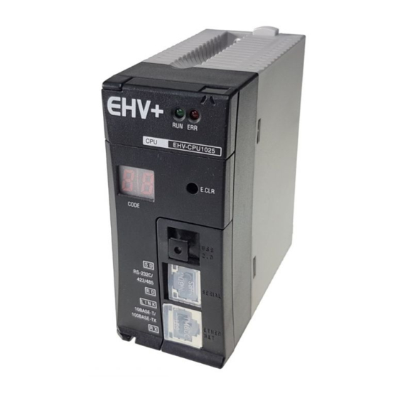
Chapter 2 Specifications CPU module 2.3.1 Module features EHV-CPU1006 Module features (Approx. 0.2kg (0.4lb.)) Lock button EHV-CPU1025 (Approx. 0.2kg (0.4lb.)) Type (Weight) EHV-CPU1051 (Approx. 0.2kg (0.4lb.)) EHV-CPU1102 ERR LED (Approx. 0.2kg (0.4lb.)) 750mA RUN LED Current consumption Dimensions E.CLR button (mm (in.)) 7-segment LED 45 (1.77) - Page 15 Description USB port supports gateway function (with EHV-CoDeSys) only. USB cable is not included with CPU package communication nor supplied by Hitachi-IES. Use type-B USB cable. port Serial Serial port has both gateway function (with EHV-CoDeSys) and IEC programming function supporting communication Modbus-RTU master and general purpose communication.
-
Page 16: Performance Specifications
Chapter 2 Specifications 2.3.2 Performance specifications Table 2.4 Performance specifications Item Specification EHV-CPU1006 EHV-CPU1025 EHV-CPU1051 EHV-CPU1102 User program memory 64KB 256KB 512KB 1024KB Source file memory Data memory (non retain) 256KB Data memory (retain) 16KB (incl. 4KB persistent variables) 16KB (2KB/slot × 8) Field bus memory No. -
Page 17: Serial Port Specifications
Chapter 2 Specifications 2.3.3 Serial port specifications (1) RS-232C [1]SG [2]CD Port from a front view of module [3]ER1 [4]ER2 [5]SD [6]RD [7]DR1 [8]RS Figure 2.1 Circuit diagram and Pin No. of RS-232C Table 2.6 List of signal of RS-232C Direction Signal Meaning... - Page 18 Chapter 2 Specifications (2) RS-422/485 [1]SG [2]N.C. [3]N.C. Port from a front view of module [4]TX [5]TXN [6]RXN [7]RX [8]N.C. Figure 2.2 Circuit diagram and Pin No. of RS-422/485 Table 2.7 List of signal of RS-422/485 Direction Signal Meaning name Host Signal ground N.C.
- Page 19 Chapter 2 Specifications Specifications of serial communication port are shown in Table 2.8. Table 2.8 Serial port specifications Item Specification Transmission speed 4,800 / 9,600 / 19,200 / 38,400 / 57,600 / 115,200 bps Interface RS-232C RS-422 RS-485 Maximum cable length 15 m (16.40 yd.) 500 m (546.81 yd.) 500 m (546.81 yd.)
-
Page 20: Power Supply Module
Chapter 2 Specifications Power supply module EH-PSA (Approx. 0.36kg (0.79lb.)) Module features Type (Weight) EH-PSD (Approx. 0.28kg (0.62lb.)) Dimensions (mm (in.)) POWER LED Front cover 60 (2.36) 95 (3.74) Power terminal block Front cover set screw Explanation of Power supply module converts externally supplied power into DC5V for CPU and I/O modules via base module function and DC24V for output terminals of power supply module. - Page 21 Chapter 2 Specifications (1) EH-PSA Item Specification Rated output voltage 5 V DC 24 V DC Maximum DC output current 3.8 A 0.4 A Efficiency 65 % minimum ( Load of 5V 3.8A 24 V 0.4A after conducting electricity for 5 minutes at room temperature and humidity) Input voltage range 85 to 264 V AC wide range...
- Page 22 Chapter 2 Specifications (2) EH-PSD Item Specification Rated output voltage 5 V DC Maximum DC output current 3.8 A Efficiency 70 % minimum (Load at 5 V DC 3.8 A) Input voltage range 21.6 to 26.4 V DC Input current 1.25 A maximum (with 24 V DC) 50 A maximum (Ta =...
-
Page 23: Base Unit
Chapter 2 Specifications Base Unit EH-BS3A (Approx. 0.22 kg (0.48 lb.)) Module features Type EH-BS5A (Approx. 0.28 kg (0.62 lb.)) (Weight) Connector for power module Mounting hole × 4 Connector for CPU module EH-BS6A (Approx. 0.31 kg (0.67 lb.)) EH-BS8A (Approx. 0.36 kg (0.79 lb.)) EH-BS11A (Approx. -
Page 24: I/O Controller
Chapter 2 Specifications I/O Controller Type (Weight) EH-IOCH2 (Approx. 0.14kg (0.31 lb.)) Module features Dimensions Lock button (mm (in.)) Rotary switch for 45 (1.77) 95 (3.74) Unit No. (1 to 5) Factory default: 1 Expansion cable connector Explanation of function I/O controller is mounted on CPU’s position of an expansion base and controls I/O modules mounted on the same base according to user program in CPU module. -
Page 25: Digital I/O Modules
Chapter 2 Specifications Digital I/O modules 2.7.1 Overview (1) Standard I/O module EH-XD8 (Approx. 0.16kg (0.32lb.)) Module features EH-XD16, XDL16 (Approx. 0.16kg (0.32lb.)) EH-XA16, XAH16 (Approx. 0.18kg (0.41lb.)) EH-YT8,EH-YTP8 (Approx. 0.16kg (0.32lb.)) EH-YT16,EH-YTP16 (Approx. 0.16kg (0.32lb.)) Type EH-YTP16S (Approx. 0.16kg (0.32lb.)) (Weight) EH-YR8B (Approx. - Page 26 Chapter 2 Specifications (2) 32-point I/O module EH-XD32, XDL32 (Approx. 0.15kg (0.3lb.)) Module features Type (Weight) EH-YT32, YTP32 (Approx. 0.15kg (0.3lb.)) LED display switch Dimensions (mm (in.)) 30 (1.18) 95 (3.74) External wiring connector EH-XD32E, XDL32E (Approx. (0.15kg (0.3lb.)) Type LED display switch (Weight) EH-YT32E, YTP32E (Approx.
- Page 27 Chapter 2 Specifications Front view Indicated contents When signal status is ON, LED lights up accordingly. Displayed group can be selected by the LED display switch. LED +16 Displayed group 10 11 12 13 14 15 0 to 15 DC INPUT EH-XD32 16 to 31 (3) 64-point I/O module...
-
Page 28: Specifications
Chapter 2 Specifications 2.7.2 Specifications (1) EH-XD8 Specification EH-XD8 DC input (common for sink and source) Input type Number of inputs 24V DC (19.2 to 30V DC) Input voltage Approx. 6.9 mA Input current Approx. 3.5 kΩ Input impedance Operating ON voltage 15V minimum voltage... - Page 29 Chapter 2 Specifications (2) EH-XD16 Specification EH-XD16 DC input (common for sink and source) Input type Number of inputs 24V DC (19.2 to 30V DC) Input voltage Approx. 4.0 mA Input current Approx. 5.9 kΩ Input impedance Operating ON voltage 15V minimum voltage OFF voltage...
- Page 30 Chapter 2 Specifications (3) EH-XDL16 Specification EH-XDL16 DC input (common for sink and source) Input type Number of inputs 24V DC (19.2 to 30V DC) Input voltage Approx. 4.0 mA Input current Approx. 5.9 kΩ Input impedance Operating ON voltage 15V minimum voltage OFF voltage...
- Page 31 Chapter 2 Specifications (4) EH-XA16 Specification EH-XA16 AC input Input type Number of inputs 100 to 120V AC (85 to 132V AC) Input voltage 4.8 to 7.6mA (100V AC / 50Hz) Input current Approx. 16kΩ (50Hz) / Approx. 13kΩ (60Hz) Input impedance Operating ON voltage...
- Page 32 Chapter 2 Specifications (5) EH-XAH16 Specification EH-XAH16 AC input Input type Number of inputs 200 to 240V AC (170 to 264V AC) Input voltage 4.3 to 8.0mA (200V AC / 50Hz) Input current Approx. 32kΩ (50Hz) / Approx. 27kΩ (60Hz) Input impedance Operating ON voltage...
- Page 33 Chapter 2 Specifications (6) EH-XD32 Specification EH-XD32 Input type DC input (Common for sink and source) Number of inputs Input voltage 24V DC (20.4 to 28.8 V DC) Input current Approx. 4.3mA Input impedance Approx. 5.6kΩ Operating ON voltage 15V minimum voltage OFF voltage 5V maximum...
- Page 34 Chapter 2 Specifications (7) EH-XDL32 Specification EH-XDL32 Input type DC input (Common for sink and source) Number of inputs Input voltage 24V DC (20.4 to 28.8 V DC) Input current Approx. 4.3mA Input impedance Approx. 5.6kΩ Operating ON voltage 15V minimum voltage OFF voltage 5V maximum...
- Page 35 Chapter 2 Specifications (8) EH-XD32E Specification EH-XD32E Input type DC input (Common for sink and source) Number of inputs Input voltage 24V DC (20.4 to 28.8 V DC) Input current Approx. 4.3mA Input impedance Approx. 5.6kΩ Operating ON voltage 15V minimum voltage OFF voltage 5V maximum...
- Page 36 Chapter 2 Specifications (9) EH-XDL32E Specification EH-XDL32E Input type DC input (Common for sink and source) Number of inputs Input voltage 24V DC (20.4 to 28.8 V DC) Input current Approx. 4.3mA Input impedance Approx. 5.6kΩ Operating ON voltage 15V minimum voltage OFF voltage 5V maximum...
- Page 37 Chapter 2 Specifications (10) EH-XD32H Item PIM-DM, PIH-DM (for replacing) EH-XD32H (This product) Series EH-150 EM/EM- Ⅱ , H-200/250/252 Input specification DC source input Number of inputs Input voltage 24 V DC (21.6 to 26.0 V DC) Input current (24V DC) Approx.
- Page 38 EM/H-200 series EH-150 series 0 4 8 1 5 9 Reverse connector 2 6 10 Replacement 3 7 11 HITACHI 16 20 24 11 21 25 18 22 26 19 23 27 Rotate 180 degrees around to connect 2 – 28...
- Page 39 Chapter 2 Specifications (11) EH-XD64 EH-XD64 Specification Input type DC input (Common for sink and source) Number of inputs Input voltage 24V DC (20.4 to 28.8 V DC) Input current Approx. 4.3mA Input impedance Approx. 5.6kΩ Operating ON voltage 15V minimum voltage OFF voltage 5V maximum...
- Page 40 Chapter 2 Specifications (12) EH-YT8 Specification EH-YT8 Output specification Transistor output (sink type) Number of outputs Rated load voltage 12/24V DC (+10%, -15%) Minimum switching current Leak current 0.1mA Maximum load 1 circuit 0.5A (0.3A MFG No.02F** or before) * current 1 common 2.4A...
- Page 41 Chapter 2 Specifications (13) EH-YT16 Specification EH-YT16 Output specification Transistor output (sink type) Number of outputs Rated load voltage 12/24V DC (+10%, -15%) Minimum switching current Leak current 0.1mA Maximum load 1 circuit 0.5A(0.3A MFG No.02F** or before)* current 1 common Output 0.3ms maximum response time...
- Page 42 Chapter 2 Specifications (14) EH-YTP8 Specification EH-YTP8 Output specification Transistor output (source type) Number of outputs Rated load voltage 12/24V DC (+10%, -15%) Minimum switching current Leak current 0.1mA Maximum load 1 circuit 0.5A(0.3A MFG No.02F** or before) * current 1 common 2.4A Output...
- Page 43 Chapter 2 Specifications (15) EH-YTP16 Specification EH-YTP16 Output specification Transistor output (source type) Number of outputs Rated load voltage 12/24V DC (+10%, -15%) Minimum switching current Leak current 0.1mA Maximum load 1 circuit 0.5A (0.3A MFG No.02F** or before * current 1 common Output...
- Page 44 Chapter 2 Specifications (16) EH-YTP16S Specification EH-YTP16S Output specification Transistor output (source type) Number of outputs Raged load voltage 12/24V DC (+10%, -15%) Minimum switching current Leak current 0.1mA Maximum load 1 circuit 0.8A current 1 common Output 0.3ms maximum response time 1ms maximum Insulation system...
- Page 45 Chapter 2 Specifications (17) EH-YR8B Specification EH-YR8B Output specification Relay output Number of outputs Rated load voltage 100/240V AC , 24V DC Minimum switching current 1mA (5V DC), except after a great current switching Leak current None Maximum load 1 circuit current 1 common Output...
- Page 46 Chapter 2 Specifications (18) EH-YR12 Specification EH-YR12 Output specification Relay output Number of outputs Rated load voltage 100/240V AC, 24V DC Minimum switching current 1mA (5V DC), except a great current switching Leak current None Maximum load 1 circuit current 1 common Output 10ms maximum...
- Page 47 Chapter 2 Specifications (19) EH-YR16 Specification EH-YR16 Output specification Relay output Number of outputs Rated load voltage 100/240V AC, 24V DC Minimum switching current 1mA (5V DC), except after a great current switching Leak current None 1 circuit Maximum load current 8A (Ambient temperature 40 °...
- Page 48 Chapter 2 Specifications (20) EH-YS4 Specification EH-YS4 Output specification Triac output Number of outputs Rated load voltage 100/240V AC (85 to 250V AC) Minimum switching current 100mA Leak current 5mA maximum Maximum load 1 circuit 0.5A current 1 common Output 1ms maximum response time 1ms + 1/2 cycle maximum...
- Page 49 Chapter 2 Specifications (21) EH-YS16 Specification EH-YS16 Output specification Triac output Number of outputs Rated load voltage 100/240V AC (85 to 250V AC) Minimum switching current 10mA Leak current 1 circuit 0.3A Maximum load current 4A (Ambient temperature 45 ° C), see the following derating table 1 common Output 1ms maximum...
- Page 50 Chapter 2 Specifications (22) EH-YT32 Specification EH-YT32 Output specification Transistor output (sink type) Number of outputs Rated load voltage 12/24V DC (+10%, -15%) Minimum switching current Leak current 0.1mA Maximum load 1 circuit 0.2A current 1 common 4A * Output 0.3ms maximum response time 1ms maximum...
- Page 51 Chapter 2 Specifications (23) EH-YTP32 Specification EH-YTP32 Output specification Transistor output (source type) Number of outputs Rated load voltage 12/24V DC (+10%, -15%) Minimum switching current Leak current 0.1mA Maximum load 1 circuit 0.2A current 1 common 4A * Output 0.3ms maximum response time 1ms maximum...
- Page 52 Chapter 2 Specifications (24) EH-YT32E Specification EH-YT32E Output specification Transistor output (sink type) Number of outputs Rated load voltage 12/24V DC (+10%, -15%) Minimum switching current Leak current 0.1mA Maximum load 1 circuit 0.2A current 1 common Output 0.3ms maximum response time 1ms maximum Insulation system...
- Page 53 Chapter 2 Specifications (25) EH-YTP32E Specification EH-YTP32E Output specification Transistor output (source type) Number of outputs Rated load voltage 12/24V DC (+10%, -15%) Minimum switching current Leak current 0.1mA Maximum load 1 circuit 0.2A current 1 common Output 0.3ms maximum response time 1ms maximum Insulation system...
- Page 54 Chapter 2 Specifications (26) EH-YT32H Item POM-TM, POH-TM (for replacing) EH-YT32H (This product) EM/EM-II, H-200/250/252 Series EH-150 Output specification Transistor output (sink type) Number of outputs Rated load voltage 5/12/24V DC (5 to 27V DC) Minimum switching current 1 mA Leak current 0.05 mA maximum Maximum output saturation voltage...
- Page 55 EM/H-200 series EH-150 series 0 4 8 1 5 9 Reverse connector 2 6 10 Replacement 3 7 11 HITACHI 16 20 24 11 21 25 18 22 26 19 23 27 Rotate 180 degrees around to connect 2 – 45...
- Page 56 Chapter 2 Specifications (27) EH-YT64 Specification EH-YT64 Output specification Transistor output (sink type) Number of outputs Rated load voltage 12/24V DC (+10%, -15%) Minimum switching current Leak current 0.1mA Maximum load 1 circuit 0.1A current 1 common 3.2A Output 0.3ms maximum response time 1ms maximum Insulation system...
- Page 57 Chapter 2 Specifications (28) EH-YTP64 Specification EH-YTP64 Output specification Transistor output (source type) Number of output points Rated load voltage 12/24V DC (+10%, -15%) Minimum switching current Leak current 0.1mA Maximum load 1 circuit 0.1A current 1 common 3.2A Output 0.3ms maximum response time 1ms maximum...
-
Page 58: Analog I/O Modules
Chapter 2 Specifications Analog I/O Modules 2.8.1 Standard analog modules EH-AX44 Module features (Approx. 0.18kg (0.41lb.)) EH-AX8V, AX8H (Approx. 0.18kg (0.41lb.)) EH-AX8I, AX8IO (Approx. 0.18kg (0.41lb.)) EH-AY22 Type (Weight) (Approx. 0.18kg (0.41lb.)) EH-AY2H (Approx. 0.18kg (0.41lb.)) EH-AY4V, AY4H (Approx. 0.18kg (0.41lb.)) EH-AY4I Terminal (Approx. - Page 59 Chapter 2 Specifications (1) EH-AX44 Specification EH-AX44 4 to 20mA Current range 0 to 10V DC Voltage range Current 4 (Ch.0 to 3) Number of channels Voltage 4 (Ch.4 to 7) 12 bits Resolution 5ms maximum Conversion time ±1% maximum of full-scale Overall accuracy Current Approx.
- Page 60 Chapter 2 Specifications (2) EH-AX8V EH-AX8V Specification 0 to 10V DC Voltage range Number of channels 12 bits Resolution 5ms maximum Conversion time ±1% maximum of full-scale Overall accuracy Input impedance Approx. 100kΩ Channel and Internal circuit Photo-coupler insulation Insulation system Between channels No insulation Removable type screw terminal block (M3)
- Page 61 Chapter 2 Specifications (3) EH-AX8H EH-AX8H Specification -10 to +10V DC Voltage range Number of channels 12 bits Resolution 5ms maximum Conversion time ±1% maximum of full-scale Overall accuracy Input impedance Approx. 100kΩ Channel and Internal circuit Photo-coupler insulation Insulation system Between channels No insulation Removable type screw terminal block (M3)
- Page 62 Chapter 2 Specifications (4) EH-AX8I EH-AX8I Specification 4 to 20mA Current range Number of channels 12 bits Resolution 5ms maximum Conversion time ±1% maximum of full-scale Overall accuracy Input impedance Approx. 100Ω Channel and Internal circuit Photo-coupler insulation Insulation system Between channels No insulation Removable type screw terminal block (M3)
- Page 63 Chapter 2 Specifications (5) EH-AX8IO EH-AX8IO Specification 0 to 22mA Current range Number of channels 12 bits Resolution 5ms maximum Conversion time ±1% maximum of full-scale Overall accuracy Input impedance Approx. 100Ω Channel and Internal circuit Photo-coupler insulation Insulation system Between channels No insulation Removable type screw terminal block (M3)
- Page 64 Chapter 2 Specifications (6) EH-AY22 EH-AY22 Specification 4 to 20mA Current range 0 to 10V DC Voltage range Current 2 (Ch.2 to 3) Number of channels Voltage 2 (Ch.0 to 1) 12 bits Resolution 5ms maximum Conversion time ±1% maximum of full-scale Overall accuracy Current External load...
- Page 65 Chapter 2 Specifications (7) EH-AY2H EH-AY2H Specification -10 to +10V DC Voltage range Number of channels 12 bits Resolution 5ms maximum Conversion time ±1% maximum of full-scale Overall accuracy External load resistance 10kΩ minimum Channel and Internal circuit Photo-coupler insulation Insulation system Between channels No insulation...
- Page 66 Chapter 2 Specifications (8) EH-AY4I EH-AY4I Specification 4 to 20mA Current range Number of channels 12 bits Resolution 5ms maximum Conversion time ±1% maximum of full-scale Overall accuracy External load resistance 350Ω maximum Channel and Internal circuit Photo-coupler insulation Insulation system Between channels No insulation Removable type screw terminal block (M3)
- Page 67 Chapter 2 Specifications (9) EH-AY4V EH-AY4V Specification 0 to 10V DC Voltage range Number of channels 12 bits Resolution 5ms maximum Conversion time ±1% maximum of full-scale Overall accuracy External load resistance 10kΩ minimum Channel and Internal circuit Photo-coupler insulation Insulation system Between channels No insulation...
- Page 68 Chapter 2 Specifications (10) EH-AY4H EH-AY4H Specification –10 to +10V DC Voltage range Number of channels 12 bits Resolution 5ms maximum Conversion time ±1% maximum of full-scale Overall accuracy External load resistance 10kΩ minimum Channel and Internal circuit Photo-coupler insulation Insulation system Between channels No insulation...
-
Page 69: High Resolution Analog Modules
Chapter 2 Specifications 2.8.2 High resolution analog modules (1) EH-AXH8M EH-AXH8M (Approx. 0.15kg Module features (0.34lb.)) Type (Weight) EH-AYH8M (Approx. 0.18kg EH-AXH8M (0.41lb.)) Dimensions (mm (in.)) Setting switch 30 (1.18) 95 (3.74) Current / voltage switch EH-AYH8M Setting switch Current / voltage switch Name Description... - Page 70 Chapter 2 Specifications Specification EH-AXH8M 0 to 22mA / 4 to 22mA Current range 0 to 10V DC / -10 to +10V DC Voltage range Number of channels 8 (current or voltage is selected in 4-ch group.) 0.002mA or 1/16384 (14 bits) Current Resolution 1mV or 1/16384 (14 bits)
- Page 71 Chapter 2 Specifications Setting switch Support to analog data and digital data Switch Setup Function 0 to 10 V DC 3FFFH(16383) 1, 2 Input range setting for ch.0 to 3 Resolution 1/16384 0 to 10 V DC 2710H(10000) -10 to +10 V DC 1FFFH(8191) 0 to 22 mA 1388H(5000)
- Page 72 Chapter 2 Specifications (2) EH-AYH8M EH-AYH8M Specification 0 to 22mA / 4 to 22mA Current range 0 to 10V DC Voltage range Number of channels 8 (current or voltage is selected in 4-ch group.) 0.002mA or 1/16384 (14 bits) Current Resolution 1mV or 1/16384 (14 bits) Voltage...
- Page 73 Chapter 2 Specifications Setting switch Support to analog data and digital data Setup Function 0 to 10 V DC 1, 2 Output range setting for ch.0 to 3 0 to 10 V DC Resolution 1mV 0 to 22 mA Resolution 1/16384 4 to 22 mA 3, 4 Output range setting for ch.4 to 7...
-
Page 74: Rtd Input Analog Module
Chapter 2 Specifications 2.8.3 RTD input analog module EH-PT4 EH-PT4 (Approx. 0.18kg (0.41lb.)) Module features Type (Weight) Dimensions (mm (in.)) 30 (1.18) 95 (3.74) Terminal block cover Setting switch Terminal block Name Description Terminal block The terminal block is to connect I/O signals. It is removable type. M3 screws are used. Use a crimping terminal fitting with screw diameter. - Page 75 Chapter 2 Specifications EH-PT4 Specification Platinum resistance thermometer Pt100 (JIS C 1604-1989) / Pt1000 Applicable resistance thermometer Signed 15 bits Temperature conversion data -20 to 40 ° C ± 0.1 ° C @25 ° C ( ± 0.5 ° C @0 to 55 ° C) (Pt100) -50 to 400 °...
-
Page 76: Thermocouple Input Analog Module
Chapter 2 Specifications 2.8.4 Thermocouple input analog module EH-TC8 Type (Weight) EH-TC8 (Approx. 0.16kg (0.35lb.)) Module features Dimensions (mm (in.)) 95 (3.74) 30 (1.18) Terminal block cover Setting switch Terminal block Name Description Terminal block The terminal block is to connect I/O signals. It is removable type. M3 screws are used. Use a crimping terminal fitting with screw diameter. - Page 77 Chapter 2 Specifications EH-TC8 Specification Applicable thermocouple types (selectable) Conforms to JIS C 1602-1995 Type K, E, J, T, B, R, S, N Signed 15 bits Temperature conversion data Accuracy guaranteed range Input range Type -200 to 1200°C 0.4% (FS) -270 to 1370°C -200 to 900°C 0.3% (FS) -270 to 1000°C...
- Page 78 Chapter 2 Specifications Item Switch setup Setting contents Thermocouple sensor types (Common to all channels) Type K Type E Type J Type T Type B Type R Type S Type N Celsius ( ° C) / Fahrenheit ( ° F) switching Celsius ( °...
-
Page 79: Special Modules
Chapter 2 Specifications Special modules 2.9.1 Positioning module : EH-POS Module features Type (Weight) EH-POS (Approx. 0.17kg (0.37lb.)) Dimensions (mm (in.)) 30 (1.18) 95 (3.74) Reset switch Positioner connector I/O connector DIP switch Name Description Reset switch Hardware-reset switch. Positioner connector This is used for connecting a special programming console called positioner. - Page 80 Chapter 2 Specifications Specifications Item Specification Number of control axes 1 axis Highest frequency 400 k pulse/s Positioning data Capacity 256 points Setting procedure 1. Sequence program 2. Positioner (Note, a positioner is optional.) Positioning Method 1. Absolute system 2. Absolute system + Increment system 3.
- Page 81 Chapter 2 Specifications Specifications (continued from the preceding page) Item Specification Output Pulse chain (CW/CCW) output 1. Open collector output photo-coupler insulation (30 V DC at the maximum, 30 Clock + Direction signal mA resistive load) (CK/Direction) pulse output 2. Line driver output photo-coupler insulation (5 V DC) 100 μA Maximum leak current Maximum voltage drop at ON...
-
Page 82: High Speed Counter Module : Eh-Cu/Cue
Chapter 2 Specifications 2.9.2 High speed counter module : EH-CU/CUE Module features Type (Weight) EH-CU (0.16kg (0.35lb.)) EH-CU: 2-ch High counter, EH-CUE: 1-ch High speed counter EH-CUE (0.16kg (0.35 lb.)) Dimensions (mm (in.)) 95 (3.74) 30 (1.18) Reset switch RESET Wiring connector EH-CU Setting DIP switch... - Page 83 Chapter 2 Specifications Purpose Applied switch Bit1 Bit 2 Explanation Select the counter mode 2-phase counter (100 kHz at the maximum) (Common between 1-phase counter (CW, CCW) channels) 1-phase counter (CK, UP/DOWN) Bit 1-2 3 4 5 6 7 8 9 10 2-phase multiplied by 4 counter (25 kHz at the maximum) Purpose Applied switch...
- Page 84 Chapter 2 Specifications Specifications Item Specification Type EH-CU EH-CUE Number of channels Number of counts at the maximum 32 bits(0 to 4,294,967,295) Maximum frequency 100 k Hz (25 k Hz at multiplied by 4) Count mode Select by setting of DIP switch. (EH-CU is common to both channels.) 2-phase, 1-phase (CW/CCW, CK, U/D), 2-phase multiplied by 4 Differential input current 4 mA minimum...
- Page 85 Chapter 2 Specifications Specifications of I/O terminal EH-CU Terminal Meaning of signal configuration Connects to a 12 to 24V DC power supply at Vin A Vin A using voltage input. A (+) A (+) Connects (+) polarity at using differential input. Phase A Connects an open collector signal at using A (-)
- Page 86 Chapter 2 Specifications EH-CUE Terminal Meaning of signal configuration Connects to a 12 to 24V DC power supply at N.C. Vin A using voltage input. N.C. A (+) Connects (+) polarity at using differential input. Phase A Connects an open collector signal at using N.C.
-
Page 87: Serial Interface Module : Eh-Sio
Chapter 2 Specifications 2.9.3 Serial interface module : EH-SIO Module features Type (Weight) EH-SIO (Approx. 0.13kg (0.29lb.)) Dimensions (mm (in.)) Reset switch 30 (1.18) 95 (3.74) RS-232C connector (Port 1) RS-232C connector Port 2 (selectable) RS-422/485 connector Communication setup switch Name Description Reset switch... - Page 88 Chapter 2 Specifications Communication setup switch Setting Details Communication speed setup Bit 1, 2, 3, and 4 are used for the communication speed setting. - DIP Sw1 is for port 1 setup Bit1 Bit2 Bit3 Bit4 Communication speed Do not set these patterns. - DIP Sw2 is for port 2 setup 1 2 3 4 5 6 7 8...
- Page 89 Chapter 2 Specifications Functional specifications Item Specification Mounting position Basic base and Expansion base (cannot mount on Remote base) The number of units to be mounted Unlimited within the range of power supply capacity of the power module. Supporting communication mode No protocol (General purpose communication), Modbus mater (RTU) Communication specifications Item...
-
Page 90: Profibus-Dp Master Module : Eh-Rmp
Chapter 2 Specifications 2.9.4 PROFIBUS-DP master module : EH-RMP Type (Weight) EH-RMP (Approx. 0.13kg (0.28Ib.)) Module features Dimensions (mm (in.)) Connector 1 Reset switch 30 (1.18) 95 (3.74) DIP switch Termination switch Connector 2 Name Description Connector 1 Connect to PC (configurator), 9pin male Sub-D Be careful, this connector become hot. - Page 91 Chapter 2 Specifications Specifications Item Specification The number of modules 8 / CPU (slot 0 to 7 only) Number of slaves Up to 124 slaves Output data 256 words Input data 256 words Data transfer rate : Max segment length 9.6 kbps: 1200 m 19.2 kbps:...
-
Page 92: Accessories
Chapter 2 Specifications 2.10 Accessories 2.10.1 Dummy module: EH-DUM Type (Weight) EH-DUM (Approx. 0.06kg (0.132lb.)) Module features Dimensions (mm (in.)) 95 (3.74) 30 (1.18) Function This module is used for protecting the un-mounted slot. 2.10.2 Expansion cable EH-CB5A / 10A / 20A Features Type Approx. -
Page 93: Installation
Chapter 3 Programming Installation 3.1.1 Installation of EHV-CoDeSys 1. Double click setup file 2. Follow the instructions N o t e .NET framework V3.5 is necessary to be installed for EHV-CoDeSys. If it is not installed, the installation of EHV-CoDeSys stops and message appears as right window. -
Page 94: Installation Of Usb Driver
Chapter 3 Programming 3.1.2 Installation of USB driver 1. Plug in USB cable to CPU module. 2. Popup window appears at right-bottom of screen. Click the popup window. 3. Click “Install from a list or specific location (Advanced)” and “Next” button. 4. - Page 95 Chapter 3 Programming 5. USB driver installation is in progress. 6. USB driver installation has been completed. Click “Finish” to close the wizard. 3 – 3...
-
Page 96: Startup
Chapter 3 Programming Startup In the first use, you need to specify the type of development activity “Standard” or “Professional” you engage in the most. This setting can be changed at any time in the menu [Tools]-[Options]-[Features] as below. Click [Predefined feature sets...] 3 –... - Page 97 Chapter 3 Programming Click icon or choose [File]-[New Project...] to create a new project file. Then New Project dialog box appears as below. Choose “Standard project”, enter new file name, specify location and click [OK]. Choose CPU type and programming language and click [OK]. Available languages are as follows.
- Page 98 Chapter 3 Programming Initial screen shot of EHV-CoDeSys is shown below. Properties Variable declaration Editor Toolbox Device Messages In the default setting, Device tree is behind the POU window. Click Devices tab to show it. “Toolbox” and “Properties” windows can be shown by [View] menu. 3 –...
-
Page 99: I/O Configuration
Chapter 3 Programming I/O Configuration 3.3.1 Plug Device (I/O configuration) Right click onslot and choose “Plug Device...”. Choose I/O module for each slot. The next slot can be configured by clicking next empty slot without closing the Plug Device window every time. -
Page 100: Scan For Devices
Chapter 3 Programming Configure I/O modules according to the list below. Model names Device Names EH-XD8, 16 16 Digital input EH-XA16, H16 EH-XD32, 32E, 32H 32 Digital input EH-XD64 64 Digital input EH-YR8B, 12, 16 16 Digital output EH-YT8, 16 EH-YTP8, 16, 16S EH-YS4, 16 EH-YT32, 32E, 32H... -
Page 101: Expansion Unit
Chapter 3 Programming 3.3.3 Expansion unit Instead of “Plug Device”, choose “Add Device” to configure expansion units. EHV-CPU1025 to CPU1102 allows to expand up to 5 expansion bases. The low end type “EHV-CPU1006” is not expandable. 3 – 9... -
Page 102: Eh-Rmp (Profibus) Configuration
Chapter 3 Programming 3.3.4 EH-RMP (Profibus) configuration Separate configuration by Sycon is required for EH-RMP. In EHV-CoDeSys, total size of input and output must be configured by adding digital in/output 16 module. Choose “Add Device” on EH-RMP and choose digital input 16 or digital output 16 module according to actual total size of slave units. -
Page 103: I/O Address
Chapter 3 Programming 3.3.5 I/O address I/O addresses and variable names can be linked in two different ways: Global variable or Local variable as below. [Global variable] Double click on plugged I/O module or right click and choose “Edit Object”. I/O-Bus Mapping window appears as below. - Page 104 Chapter 3 Programming Input any variable names in the field “Variable” according to your system. After defining variable names, they will be automatically listed up when it is used in all POU with assist of auto-complete. If a variable is already used (declared) in POU or global variable list, it can be taken by clicking icon in I/O mapping window.
- Page 105 Chapter 3 Programming [Local variable] Local variables are defined in each POU and valid only in the POU. If new variable name is used in the first time, Auto Declare window will appear as below. In this window, there is the input field “Address”.
- Page 106 Chapter 3 Programming I/O address example of 64 points output module Bit number BOOL BYTE WORD DWORD LWORD Bit 0 %QX7.0 %QB7 %QW3 %QD1 %QL0 Bit 1 %QX7.1 Bit 2 %QX7.2 Bit 3 %QX7.3 Bit 4 %QX7.4 Bit 5 %QX7.5 Bit 6 %QX7.6 Bit 7...
-
Page 107: I/O-Update
Chapter 3 Programming I/O-update Input data is read at the beginning of a task and output data is written at the end of a task. I/O-update settings are configured in “PLC settings” in Device tab. Be noted that only used I/Os in program are updated. Update IO while in stop If this option is activated (default), the values of the input and output channels get also updated when the PLC is stopped. - Page 108 Chapter 3 Programming Reset all outputs in STOP This setting is in [Device]-[Configuration]. If “Reset all outputs in STOP” is “Yes” (default), all the PLC outputs including counter outputs and pulse train output of positioning module are reset because it is reset by a certain hardware signal running on the back plane bus.
-
Page 109: Pou And Task
POU and task One application has at least one POU and one task as shown below. POU stands for Program Organization Unit. This can be assumed as a paper to create your program. Only one programming language can be used in one POU. If you need another language, add POU by right click on “Application”... - Page 110 Chapter 3 General Specifications Task POU does not have information how to execute POU. This information is handled by task. Put priority, choose type of task and add or remove POU accordingly. Priority (0-3) 0 is the highest priority, 3 is the lowest. Cyclic task The task will be processed cyclic according to the time definition given in the field “Interval”.
-
Page 111: Local And Global Variables
Chapter 3 General Specifications Local and global variables [Local variable] If new variable name is used in POU, Auto Declare window appears as below. If the field “Address” is remained as empty, this variable will be assigned in a certain memory area of CPU. Click [OK] button, this variable is registered in declaration part of POU as below. - Page 112 Chapter 3 General Specifications [Global variable] If variables need to be commonly used in all POUs, “Global Variable List” must be created by right click on Application as below. If new variable name is used in POU, Auto Declare window appears as shown in local variables. Choose “VAR_GLOBAL”...
-
Page 113: Communication Settings
Chapter 3 General Specifications Communication settings EHV+ series CPUs have 3 types of communication ports as below. Ethernet port Default value IP address: 192.168.0.1 Subnet mask: 255.255.255.0 Function - Gateway (communication with EHV-CoDeSys) (default port number: 1740) - Modbus-TCP client/server... - Page 114 Chapter 3 General Specifications How to configure Double click on “Device (EHV-CPUxxxx)” or right click and choose “Edit Object”. “Device” window will appear as below. Choose “Communication Settings” tab and click “Add gateway”. “Gateway” window will appear. Click “OK”. Sine the communication type between EHV-CoDeSys and gateway (in PC) is TCP/IP, displayed driver name is “TCP/IP”...
- Page 115 Chapter 3 General Specifications The gateway is displayed as below. Click “Scan network” to search available device in the network. If CPU is found, it is displayed as below. Click “Set active path” to choose as the target device. N o t e Even if all Ethernet cable, USB cable and serial cable are connected, only the first detected device is shown.
-
Page 116: Login
Chapter 3 General Specifications Login Login After programming, click or choose [Build] in Build menu. If compiling fails, error information is shown at “Description” field as follows. Double click the message to jump to the part to be corrected. N o t e If unknown message appears, it is recommended to [Clean all] in Build menu. - Page 117 Chapter 3 General Specifications When logging in successfully, green circle icon is displayed at [Device]. If mounted I/O modules are matched with configured ones, green icon is displayed at each I/O module also. If any mounted I/O module is mismatched, red triangle icon is displayed at mismatched module as below. Online change To change your program in running CPU (online change), you have to logout at first.
-
Page 118: Boot Application
Chapter 3 General Specifications Boot application The basic overview of downloading is shown as below picture. Be noted that an application (compiled user program) is downloaded to volatile RAM memory of the CPU, which means the application is lost when power is removed. If your application needs to be saved in non-volatile FLASH memory, choose [Create boot application] in Online menu while Login. -
Page 119: Source Download / Upload
Chapter 3 General Specifications 3.10 Source Download / Upload Besides boot application, source file can be saved in the CPU module, which enables you to upload original program file from PLC even if you don’t have it in your PC. Some extra files can be added to source file as below. Choose according to your necessity. -
Page 120: Run / Stop / Reset
Stop switch definition Definition of stop position of run/stop switch can be configured as “Stop” or “Reset warm” in CPU configuration. Default setting is “Reset warm” since it is almost same behaviour of original “Stop” for existing Hitachi PLC. 3 – 28... -
Page 121: Global Network Variables
Chapter 3 General Specifications 3.12 Global network variables Any variables can be listed in global network variable list, which are sent to all other CPUs in the network with broadcast address of UDP/IP. Global net work variable function is available only in professional setting. Refer to 3.2 Start up how to change the environment setting. - Page 122 Chapter 3 General Specifications Network type: Choose “UDP”. Task: Choose any one task. The variables are sent at the end of a task cycle. List identifier: If more than 2 global variable list is configured, set a number in ascending order. Cyclic transmission: Since variables are sent every task cycle, set interval time as same or bigger than cycle time of configured task.
- Page 123 Chapter 3 General Specifications Login Set the communication path for Send-CPU and login (download application). After logout, right click on “Application” of Receive-CPU and choose “Set Active Application”. Set the communication path for Receive-CPU and login (download application). Active Active You can see the variable “test_var”...
-
Page 124: Modbus-Tcp/Rtu
3.13 Modbus-TCP/RTU 3.13.1 Introduction Supported function codes are shown in the below table. EH-SIO Function code Modbus-TCP Master Modbus-TCP Slave Modbus-RTU Master Modbus-RTU Master 0x01 Read Coils 0x02 Read Discrete Inputs 0x03 Read Holding Registers 0x04 Read Input Registers 0x05 Write Single Coil 0x06 Write Single Register... -
Page 125: Modbus-Tcp Master (Client)
Chapter 3 General Specifications 3.13.2 Modbus-TCP master (client) Right click on “Device” and choose “Add Device...”. “Add Device” window appears. Click “Ethernet” and [Add Device] button. With “Add device” window opened, click “Ethernet” in the device tree. Then available devices will be shown in the “Add Device”... - Page 126 Chapter 3 General Specifications Be sure to configure all slave modules to be controlled. Function codes to be sent are configured in each slave. Double click a slave unit to open configuration window. Set IP address, response timeout and port number as below. Unit-ID is used when a Modbus-gateway (Ethenet to serial) device is used.
- Page 127 Chapter 3 General Specifications Configure each parameter as below. If the Trigger setting is “Rising edge”, trigger variable (BOOL) will be automatically assigned in %QX address. Data of Modbus will be assigned to %IW or %QW as seen in “ModbusTCPSlave I/O Mapping” tab. Read data from slave is assigned to input area (%IW) and data to be written to slave is assigned to output area (%QW).
-
Page 128: Modbus-Tcp Slave (Server)
Chapter 3 General Specifications 3.13.3 Modbus-TCP slave (server) Right click on “Ethernet” and choose “Add Device...”. Click “Modbus TCP Slave Device” in the “Add Device” window and [Add Device] button Configure each parameter as below. According to the size of “Holding Registers” and “Input Registers”, data area will be assigned as seen in “ModbusTCPSlave Device I/O Mapping”... -
Page 129: Modbus-Rtu Master
Although CPU’s Serial port does not support Modbus-RTU slave function, slave device (Modbus Serial Device) is available since it is common device for other manufacturer’s CoDeSys based CPUs. Please do not choose this device with EHV+ series CPUs. 3 – 37... - Page 130 Chapter 3 General Specifications With “Add device” window opened, click “Modbus_Master_COM_Port” in the device tree. Then “Modbus Slave, COM Port” is shown in the “Add Device” window. Click “Modbus Slave, COM Port” and [Add Device] button according to your Modbus system configuration. e.g. if 3 slaves are to be controlled, add 3 times of slave devices. Be sure to configure all slave modules to be controlled.
- Page 131 Chapter 3 General Specifications Configure each parameter as below. If the Trigger setting is “Rising edge”, trigger variable (BOOL) will be automatically assigned in %QX address. Data of Modbus will be assigned to %IW or %QW as seen in “ModbusGenericSerialMaster I/O Mapping” tab. Read data from slave is assigned to input area (%IW) and data to be written to slave is assigned to output area (%QW) N o t e When trigger type is set as “Rising edge”, do not change the trigger bit too often, otherwise rising edge could be...
-
Page 132: Eh-Sio
Chapter 3 General Specifications 3.14 EH-SIO 3.14.1 Supported function Any version of EH-SIO works with “EHV+” however, supported function is different from EHV/EH series as below. Function EHV+ EHV/EH-CPU Modbus-RTU master Modbus-ASCII master Modbus-RTU/ASCII slave General purpose communication (Free protocol) Hi-Protocol Simple data link X = Supported, - = Not supported... -
Page 133: Modbus-Rtu Master
Chapter 3 General Specifications 3.14.3 Modbus-RTU master Right click on “Device” and choose “Add Device...”. “Add Device” window appears. Click “Modbus SIO-COM” and [Add Device] button. With “Add device” window opened, click “Modbus__SIO_COM” in the device tree. Then available devices will be shown in the “Add Device”... - Page 134 Chapter 3 General Specifications With “Add device” window opened, click “Modbus_Master_COM_Port” in the device tree. Then “Modbus Slave, COM Port” is shown in the “Add Device” window. Click “Modbus Slave, COM Port” and [Add Device] button according to your Modbus system configuration. e.g. if 3 slaves are to be controlled, add 3 times of slave devices. Be sure to configure all slave modules to be controlled.
-
Page 135: General Purpose Communication
Chapter 3 General Specifications 3.14.4 General purpose communication Besides Modbus-RTU function, EH-SIO supports general purpose communication same as CPU port. Add “SysCom” library by clicking “Add library” on Library manager. Only the difference from CPU port is COM port number. Be sure to set the same COM port number as “EH-SIO configuration” window. Refer to 3.15.3 Serial communication for further information. -
Page 136: Libraries
3.15 Libraries 3.15.1 How to install In order to read/write EHV+ series CPU’s specific information, following libraries are available. Add necessary CmpHIESLib by choosing “Add library” as shown below. CmpHIESLib is Hitachi-IES’s special library including; Library for counter module (EH-CU/CUE) -
Page 137: Real Time Clock
Chapter 3 General Specifications 3.15.2 Real time clock Add “CAA Real Time Clock Extern” library by clicking “Add library” on Library manager. In the CAA Real Time Clock Extern libraries, GetDateAndTime and SetDateAndTime are supported. Be noted that the others are not supported..Supported ...Supported ...Not supported... -
Page 138: Serial Communication
Chapter 3 General Specifications Declare instance of the function blocks and necessary variables as below. By rising edge of xExecute bit of SETDATEANDTIME, data in dtDateAndTime is written to the RTC device. By rising edge of xExecute bit of GETDATEANDTIME, current date and time is read out to the variable connected to dtDateAndTime as shown below. - Page 139 Chapter 3 General Specifications It is recommended to use ST language for serial communication settings since it is more flexible..COM1 ...Non parity ...1 stop bit ...baudrate 19,200bps ...buffer size 100 bytes ...Timeout 10ms ...8 bit / frame ...Connect 02 + “123” ...Connect 02 “123”...
-
Page 140: Troubleshooting
Chapter 3 General Specifications 3.16 Troubleshooting Error code The CPU has 7-segment display and error LED to indicate an error code as listed below. If two or more errors are detected at the same time, smaller error code has higher priority to be displayed. If error is detected, read the descriptake following countermeasures depending on error level. - Page 141 Chapter 3 General Specifications Err. Error name Description Applica- code [Detected when] system tion Misalignment / Microprocessor has detected an exception Stop Illegal instruction / processing in application. Privileged instruction [Always] Retain identity mismatch Retain data memory is undefined status due to Stop [Power on] battery empty.
- Page 142 Chapter 3 General Specifications 21 Error (1) If boot application and application are different, 21 error appears at power up. The reason is as follows. Each application has GUID (globally unique identifier) and this GUID is changed if the application is recompiled (Clean &...
- Page 143 Chapter 3 General Specifications Error libraries As for warnings (error code 70 to 78), special libraries called “CmpHitachiErrors” are available as below. Use them in your application program if necessary. If it is not registered in your library repository, install CmpHitachiErrors.library by choosing [Tools]-[Install library...].
-
Page 144: Version
Chapter 3 General Specifications 3.17 Version Firmware version (Target-Version) of your CPU is monitored in communication settings of Device as below. 3 – 52... -
Page 145: Installation
Chapter 4 Installation For use in safety, avoid installing the PLC in the following locations. - Excessive dusts, salty air, and/or conductive materials (iron powder, etc.) - Direct sunlight - Temperature less than 0°C or more than 55°C - Dew condensation - Humidity less than 20% or more than 90% - Direct vibration and/or impact to the unit - Corrosive, explosive and/or combustible gasses... - Page 146 Chapter 4 Installation (hardware) 109 (4.29) 14 (0.55) 50 mm (1.97in.) or more 10 mm 10 mm P L C (0.39in.) or (0.39in.) or more more 50 mm (1.97in.) or more 50 mm (1.97in.) or more Figure 4.2 External dimensions 10 mm 10 mm P L C...
-
Page 147: Loading Module
Chapter 4 Installation (hardware) Loading Module (1) Installing 1] Hook the claw at the lower section of the module to the hole in the base. 2] Press in the upper side of the module until it clicks. Note 1: Make sure the module does not come out after loading the module. -
Page 148: Wiring
Chapter 4 Installation (hardware) Wiring (1) Separation of power system Several different power sources are used with PLC, such as main power of PLC, power for I/O signal and power for external devices. These power sources should be separated as much as possible. If these power sources come from one power source, install transformers or noise filters to separate those power lines as much as possible. - Page 149 8 8 8 8 9 9 9 9 1 2 1 2 1 2 1 3 1 3 1 3 HITACHI (b) The function ground terminal (FE terminal) should use a cable of 2 mm (0.0031in ) or more and Class D grounding (100 Ω...
- Page 150 Chapter 4 Installation (hardware) (5) Input wiring for the input module DC input AC input (EH-XD16 、 E H-XD8) (EH-XA16 、 E H-XAH16) AC100V + Current-output-type 24 V DC (Example of EH-XA16) proximity switch (Example of EH-XD16) Figure 4.5 Input wiring (a) DC input module 1] When all input terminal (X0, X1, …) and the common terminal (C) are loaded with 24 V DC, the input changes to ON, and approximately 6.9 mA current in case of EH-XD8 and approximately 4 mA current in...
- Page 151 Chapter 4 Installation (hardware) (b) Wiring for 32/64-point input module (EH-XD32,EH-XD64) (Based on CE marking) Signal line Shield cable EH-XD32/64 Class D grounding Common + terminal Common line + External power supply Note: 1] Wire only the signal line through the shield cable, and provide class D grounding on the shield cable side.
- Page 152 Chapter 4 Installation (hardware) (6) Output wiring for the output module Item Relay output Relay output Transistor output Transistor output (sink type) (source type) (EH-YR12) (EH-YR16) (EH-YT16 、 E H-YT8) ( E H-YTP16 、 EH-YTP16S 、 E H-YTP8 ) Diode Diode 24 V DC + Surge killer...
- Page 153 Chapter 4 Installation (hardware) (b) Wiring for the transistor output module 1] Flywheel diode For inductive load, connect a flywheel diode in parallel. 2] S and C terminals Always connect an S terminal and C (common) terminal. If the module is used without connecting these terminals, the internal flywheel diode does not function and there is a risk that the module will malfunction or breakdown.
- Page 154 Chapter 4 Installation (hardware) (7) I/O wiring for the analog module - Do not apply excess voltage to the analog input module beyond the rated input voltage. Similarly, do not subject the module to current that exceeds the rated input current. Connecting the analog input module to a power supply other than the specified types may cause damage to the product or burning or its internal components.
- Page 155 Chapter 4 Installation (hardware) (8) Wiring to the module terminal AC Power If the number of expansion unit is 5unit, please use shielded cable for this line. Wiring for the power supply Use a 2mm (0.031in .) cable and twist it. Leave a distance of 100mm(3.94 in.) or more Shielded insulation from the signal cable and 200mm (7.87 in.) or...
- Page 156 Chapter 4 Installation (hardware) MEMO 4 – 12...
-
Page 157: Daily And Periodic Inspection
Chapter5 Maintenance In order to use the PLC in the best condition and maintain the system to operate properly, it is necessary to conduct daily and periodic inspections. Daily and Periodic Inspection (1) Daily inspection Verify the following items while the system is running. Table 5.1 Items for daily inspection Item LED display... -
Page 158: Product Life
Chapter 5 Maintenance Product Life The lifetime of electrolytic capacitors used in the power module is limited. Electrolytic capacitors are used in some of I/O modules to improve noise resistance. If the lifetime is exceeded, performance of product is not guaranteed. Be sure to conduct inspection and maintenance as follows. - Page 159 Chapter 5 Maintenance How to replace the battery Connection part for battery Front cover [+] Red lead wire side Battery [-] Black lead wire side Battery connector Space for lead wire storage Do not open the front cover more than 90 degree when installing and removing the battery.
- Page 160 Chapter 5 Maintenance MEMO 5 – 4...