Table of Contents
INSTALLATION AND OPERATION MANUAL
MANUAL DE INSTALACIÓN Y FUNCIONAMIENTO
INSTALLATIONS- UND BETRIEBSHANDBUCH
MANUEL D'INSTALLATION ET DE
FUNCTIONNEMENT
MANUALE D'INSTALLAZIONE E D'USO
Do not perform installation work, without referring to our installation manual.
No realice la instalación de este equipo, sin antes consultar este manual de instalación.
Bei der Installation unbedingt die Hinweise in der Installationsanleitung beachten.
Consulter notre manuel avant de réaliser une quelconque installation.
Realizzare l'installazione, seguendo quanto indicato in questo manuale.
Nao inicie os trabalhos de montagem, sem consultar o nosso manual de montagem.
Udfor ikke installationsarbejder uden forst at donsultere vores vejledning.
Voer geen enkele handeling uit om de apparatuur alvorens deze hadleiding te hebben
doorgelezen.
Utför inte nagra installationsarbeten utan att först läsa var installationsmanual
Μην ήσετε στην εγκατάσταση, χωρίς πριν να έχετε συμβουλευθεί αυτo το εγχειρίδιο εγκατάστασης
PSC-A64S
CENTRAL STATION
MANUAL DE INSTALAÇÄO E DE
FUNCIONAMENTO
BRUGER- OG MONTERINGSVEJLEDNING
INSTALLATIE- EN BEDIENINGSHANDLEIDING
HANDBOK FÖR INSTALLATION OCH ANVÄNDING
ΕΓΧΕΙΡΙΔΙΟΕΓΚΑΤΑΣΤΑΣΗΣΚΑΙΛΕΙΤΟΥΡΓΙΑΣ
Table of Contents

Related Manuals for Hitachi PSC-A64S


Summary of Contents for Hitachi PSC-A64S
- Page 1 PSC-A64S CENTRAL STATION INSTALLATION AND OPERATION MANUAL MANUAL DE INSTALAÇÄO E DE MANUAL DE INSTALACIÓN Y FUNCIONAMIENTO FUNCIONAMENTO INSTALLATIONS- UND BETRIEBSHANDBUCH BRUGER- OG MONTERINGSVEJLEDNING MANUEL D’INSTALLATION ET DE INSTALLATIE- EN BEDIENINGSHANDLEIDING HANDBOK FÖR INSTALLATION OCH ANVÄNDING FUNCTIONNEMENT ΕΓΧΕΙΡΙΔΙΟΕΓΚΑΤΑΣΤΑΣΗΣΚΑΙΛΕΙΤΟΥΡΓΙΑΣ MANUALE D’INSTALLAZIONE E D’USO Do not perform installation work, without referring to our installation manual.
- Page 2 WARNING: DO NOT perform installation work and electrical wiring connection by yourself. Contact your distributor or dealer of HITACHI and ask them for installation work and electrical wiring by service person. When performing the insulation test, withstand voltage test and so on, ensure to remove the FG terminal connection of TB1.
- Page 3 INSTALLATION WORK 2.3. INSTALLATION SPACE In case of installing the central stations in the vertical direction, keep a distance more than 50mm between the central stations vertically. If the distance is insufficient, the front cover of More than 50 mm the central station can not open wide enough.
- Page 4 ELECTRICAL WIRING ELECTRICAL WIRING 3.1. ELECTRICAL WIRING Up to 8 Central Stations can be connected to the H-LINK (Control line). Use the 2-core cable of 0.75-1.25 mm or the 2-core twist pair cable (Max. 1.000 m) for the transmission cable for the central station, for the outdoor unit and between indoor units (DC5V). The maximum total length of the cables shall be within 1.000 m.
- Page 5 Address 1 Address 2 Address 3 NOTE: When using the central station PSC-5S and PSC-A64S together in the same H- LINK (control line) system, set the 1 2 3 4 1 2 3 4 1 2 3 4 1 2 3 4 DSW1 not to be overlapped.
- Page 6 GROUP SETTING Judgment of H-LINKII Adaptive START Other central controller is connected in the same H-LINK (control line) system (*1) All models of other connected central controllers are PSC- A*** or HC-A*** (*1) The setting of other connected central controllers are all H-LINKII adaptive (*2) H-LINKII Non-Adaptive H-LINKII adaptive...
- Page 7 GROUP SETTING Central station Outdoor unit Indoor unit Remote Control Switch Group Group Group Group Group Group Zone As for the indoor unit The remote control switch One remote control switch without remote control group with one indoor unit group is considered as one switch, one indoor unit is is also considered as one group...
- Page 8 GROUP SETTING 4.1. GROUP SETTING PROCEDURE - The group setting consists of the master unit setting and the slave unit setting. The indoor unit, which is connected directly to the remote control switch, is set as the master unit, and the indoor unit connected with the transmission line is set as the slave unit.
- Page 9 GROUP SETTING 4.1.2. SYSTEM OF MORE THAN 17 INDOOR UNIT CONNECTED In this case, the group setting by central station is required. Group setting is for master unit (directly connected to remote control switch) and slave unit (connected by extension cable). In case that the remote control switch is not connected, the group setting by remote control switch is not available and only one master unit is controlled as one group.
- Page 10 GROUP SETTING 4.2.2. PROCEDURE OF MASTER UNIT SETTING a. Screen change for Master Unit Setting keep depressing the "CHECK" switch for 3 seconds during all the indoor unit is stopped (with "RUN" indicator OFF). The "CHECK" indicator turns ON, and it shows the state is changed to the CHECK mode.
- Page 11 GROUP SETTING • ATTENTION: - When the indication of Ref. Nº is “- -”, the indication of I.U. Add. is also “- -”. In such a case, I.U. Add. can not be changed although the “ ” (TEMP) switch is depressed. - Ref.
- Page 12 GROUP SETTING 4.3. SETTING OF SLAVE UNIT When using the remote control switch (PC-AR(T)), the half-size remote control switch (PC-ARH) or receiver kit (PC-ALH∗), after the setting of master unit, the central station automatically set the slave unit. Check for the setting state by the slave unit setting mode. 4.3.1.
- Page 13 GROUP SETTING b. Select the refrigerant system address and indoor unit address to set. The refrigerant system address is changed by depressing ∇ " " (TEMP) switch and the indoor unit address is changed by depressing "Δ" (TEMP) switch in order as shown below. In this case, the switch is kept depressing, and the indication of the refrigerant system address or the indoor unit address is fast-...
- Page 14 GROUP SETTING 4.3.3. CANCELLATION OF SLAVE UNIT SETTING a. Screen Change for Cancellation of Slave Unit Setting. Keep depressing the "CHECK" switch for 3 seconds during all the indoor unit is stopped (with "RUN" indicator OFF). The "CHECK" indicator turns ON, and it shows the state is changed to the CHECK mode.
- Page 15 INPUT/OUTPUT FUNCTION INPUT/OUTPUT FUNCTION The central station has two input functions and two output functions as shown below. 1. Simultaneous Operation/Stoppage. This function is for operating / stopping all the indoor units of the group, which is set by the central station, by the external contact signal.
- Page 16 INPUT/OUTPUT FUNCTION 7. Simultaneous Alarm Output. This function is for outputting signal outward in the case where there is any air conditioner in abnormal condition in the group set by the central station. The input function is set by DSW2 as shown in the table below: DSW Pin Nº...
- Page 17 INPUT/OUTPUT FUNCTION 2. Changing to Demand Setting Mode. Depress the “CHECK” switch and change the 7-segment indication for check to “5” (Demand Setting Mode). The LCD indication of the central station is as shown below. The state of demand setting of the Ref.
- Page 18 OPTION SETTING 5. Setting Procedure Depress the “RUN/STOP” switch and the selected group is set with demand control, and the “ ” and “DEMAND” indications appear. In the case where there is one or more group with demand setting in the zone, the " " indication of zone turns ON.
- Page 19 OPTION SETTING Indication of Option Setting Mode When the central station is changed to the slave unit setting mode, the LCD indication on the central station is as shown below. The indication of the group to be set is flickered. The Ref. Nº and I.U.
- Page 20 INITIALIZATION OF CENTRAL STATION INITIALIZATION OF CENTRAL STATION The procedure for initialization of the group setting and the optional setting is as follows. 7.1. CHANGiNG TO SELF CHECK MODE Depress the “GROUP ( )” and ”MODE” switches simultaneously, the central station is changed to the self check mode.
- Page 21 INITIALIZATION OF CENTRAL STATION 7.3. ZONE AND GROUP SETTING TABLE OF CENTRAL STATION (1) Indoor Unit Address 00 01 02 03 04 05 06 07 08 09 10 11 12 13 14 15 Fill the group number (1-4) and the group number (1-16) in the above table. Circle the unit number of the master unit.
- Page 22 INITIALIZATION OF CENTRAL STATION 7.4. ZONE AND GROUP SETTING TABLE OF CENTRAL STATION (2) Remarks Remarks Zone Group Zone Group (ex. Room name) (ex. Room name)
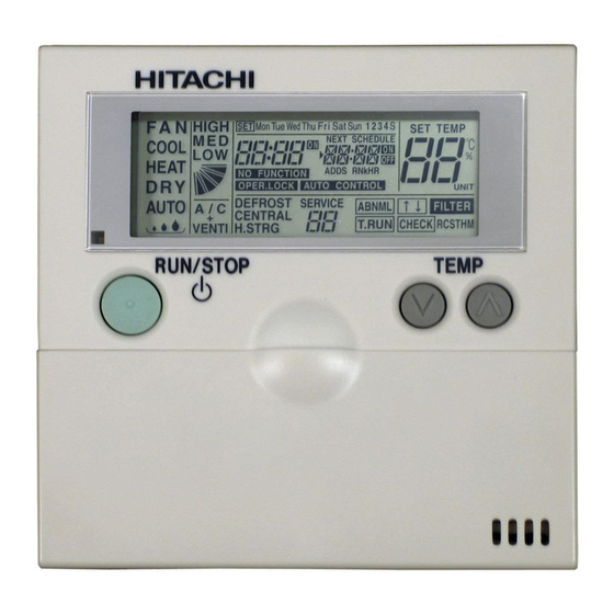
- Page 23 SWITCH NAMES AND FUNCTIONS SWITCH NAMES AND FUNCTIONS Liquid Crystal Display Selection The figure below shows all the indications for reference.The actual display during operation is different. Indication of Indication of Indication of Indication of Setting Demand Control Setting Target Timer temperature (Page 24, 25)
- Page 24 SWITCH NAMES AND FUNCTIONS About Zone and Group The central station controls plural indoor units as a unit (one indoor unit is also available). The operation unit is as follows; Minimum operation unit for central station One remote control switch group is considered as one group under Group the same control.
- Page 25 OPERATION PROCEDURE OPERATION PROCEDURE 9.1. SETTING TARGET SELECTION AND MONITORING OPERATION STATUS The central station can control up to 64 groups by each group, each zone or simultaneously . (The selected setting target can be operated and the unit operation status can be monitored.) •...
- Page 26 - The above indications show the case of setting operation mode for "Zone 3, Group 6". The same setting procedure shall be performed for other groups. - Some operation modes can not be set according to the unit model. Contact to HITACHI dealer or your distributor for details.
- Page 27 OPERATION PROCEDURE 9.3. SETTING OF TEMPERATURE, FAN SPEED AND LOUVER ANGLE • ATTENTION: Do not touch the “CHECK” switch. The “CHECK” switch is only for service use. When the “CHECK” switch is depressed by a mistake and the central station is changed to the check mode, depress the “RESET”...
- Page 28 OPERATION PROCEDURE In Case of 4-Way Cassette Type (Example) Indication Air Louver Approx. Approx. Approx. Approx. Approx. Approx. Approx. Angle 25° 30° 35° 40° 50° 55° 60° Angle Range Cooling Dry Angle Range Heat Recommended Angle NOTES: - The fixing angle of the louver shown above is the case of 4-way cassette type indoor unit. The fixing angle is different according to unit model.
-
Page 29
OPERATION PROCEDURE Prohibiting Operation by Remote Control Switch
To prohibit the operation by the remote control switch. When this function is available, the “CENTRAL” indication appears on the LCD on the remote control switch and the operation by the remote control switch is not available. 1. - Page 30 The “EMERGENCY” is indicated when the emergency stop signal is input by the outside input function. During the emergency stoppage, indoor units are stopped and the operation by the remote control switch is not available. Contact your distributor or dealer of HITACHI for details.
-
Page 31
The indication is indicated for the group with demand setting and the “DEMAND” indication flickers when the demand signal is input. In Case of Demand Setting Contact your distributor or dealer of HITACHI for details. Flickering En el caso del ajuste de solicitud
...