Mitsubishi Electric MELSEC iQ-R Series User Manual
Profibus-dp module
Hide thumbs
Also See for MELSEC iQ-R Series:
- Programming manual (2110 pages) ,
- User manual (760 pages) ,
- Reference manual (498 pages)
Table of Contents
Quick Links
Table of Contents

Related Manuals for Mitsubishi Electric MELSEC iQ-R Series


Summary of Contents for Mitsubishi Electric MELSEC iQ-R Series
- Page 1 MELSEC iQ-R PROFIBUS-DP Module User's Manual (Startup) -RJ71PB91V...
-
Page 3: Safety Precautions
SAFETY PRECAUTIONS (Read these precautions before using this product.) Before using this product, please read this manual and the relevant manuals carefully and pay full attention to safety to handle the product correctly. The precautions given in this manual are concerned with this product only. For the safety precautions of the programmable controller system, refer to the MELSEC iQ-R Module Configuration Manual. - Page 4 [Design Precautions] WARNING ● Configure safety circuits external to the programmable controller to ensure that the entire system operates safely even when a fault occurs in the external power supply or the programmable controller. Failure to do so may result in an accident due to an incorrect output or malfunction. (1) Emergency stop circuits, protection circuits, and protective interlock circuits for conflicting operations (such as forward/reverse rotations or upper/lower limit positioning) must be configured external to the programmable controller.
- Page 5 [Design Precautions] WARNING ● Especially, when a remote programmable controller is controlled by an external device, immediate action cannot be taken if a problem occurs in the programmable controller due to a communication failure. To prevent this, configure an interlock circuit in the program, and determine corrective actions to be taken between the external device and CPU module in case of a communication failure.
- Page 6 [Design Precautions] WARNING ● If a stop error occurs in the CPU module, the operating status of the DP-Master is as follows. In a redundant system, however, the operation is the same as when "CPU Error Output Mode Setting" is set to "Hold" regardless of its setting value. (1) When "CPU Error Output Mode Setting"...
- Page 7 [Design Precautions] CAUTION ● Do not install the control lines or communication cables together with the main circuit lines or power cables. Doing so may result in malfunction due to electromagnetic interference. Keep a distance of 100mm or more between those cables. ●...
- Page 8 [Installation Precautions] WARNING ● Shut off the external power supply (all phases) used in the system before mounting or removing the module. Failure to do so may result in electric shock or cause the module to fail or malfunction. [Installation Precautions] CAUTION ●...
- Page 9 [Wiring Precautions] WARNING ● Shut off the external power supply (all phases) used in the system before installation and wiring. Failure to do so may result in electric shock or cause the module to fail or malfunction. ● After installation and wiring, attach a blank cover module (RG60) to each empty slot and an included extension connector protective cover to the unused extension cable connector before powering on the system for operation.
- Page 10 [Wiring Precautions] CAUTION ● Tighten the terminal screws or connector screws within the specified torque range. Undertightening can cause drop of the screw, short circuit, fire, or malfunction. Overtightening can damage the screw and/or module, resulting in drop, short circuit, fire, or malfunction. ●...
- Page 11 [Startup and Maintenance Precautions] WARNING ● Do not touch any terminal while power is on. Doing so will cause electric shock or malfunction. ● Correctly connect the battery connector. Do not charge, disassemble, heat, short-circuit, solder, or throw the battery into the fire. Also, do not expose it to liquid or strong shock. Doing so will cause the battery to produce heat, explode, ignite, or leak, resulting in injury and fire.
- Page 12 [Startup and Maintenance Precautions] CAUTION ● Do not drop or apply shock to the battery to be installed in the module. Doing so may damage the battery, causing the battery fluid to leak inside the battery. If the battery is dropped or any shock is applied to it, dispose of it without using.
-
Page 13: Conditions Of Use For The Product
CONDITIONS OF USE FOR THE PRODUCT (1) Mitsubishi programmable controller ("the PRODUCT") shall be used in conditions; i) where any problem, fault or failure occurring in the PRODUCT, if any, shall not lead to any major or serious accident; ii) where the backup and fail-safe function are systematically or automatically provided outside of the PRODUCT for the case of any problem, fault or failure occurring in the PRODUCT. -
Page 14: Introduction
Before using this product, please read this manual and the relevant manuals carefully and develop familiarity with the functions and performance of the MELSEC iQ-R series programmable controller to handle the product correctly. When applying the program examples provided in this manual to an actual system, ensure the applicability and confirm that it will not cause system control problems. -
Page 15: Compliance With Emc And Low Voltage Directives
DIRECTIVES Method of ensuring compliance To ensure that Mitsubishi Electric programmable controllers maintain EMC and Low Voltage Directives when incorporated into other machinery or equipment, certain measures may be necessary. Please refer to one of the following manuals. • MELSEC iQ-R Module Configuration Manual •... - Page 16 MEMO...
-
Page 17: Table Of Contents
CONTENTS SAFETY PRECAUTIONS ..............1 CONDITIONS OF USE FOR THE PRODUCT . -
Page 18: Relevant Manuals
• Installation For details, refer to the following. MELSEC iQ-R Module Configuration Manual e-Manual refers to the Mitsubishi Electric FA electronic book manuals that can be browsed using a dedicated tool. e-Manual has the following features: • Required information can be cross-searched in multiple manuals. -
Page 19: Terms
TERMS Unless otherwise specified, this manual uses the following terms. Term Description Backup mode A mode to continue operation in a redundant system. This mode can continue the operation by switching the systems from the control system to the standby system when an error occurs in the control system. Buffer memory Memory in an intelligent function module to store data such as setting values and monitor values. -
Page 20: Generic Terms And Abbreviations
Unless otherwise specified, this manual uses the following generic terms and abbreviations. Generic term/abbreviation Description CPU module A generic term for the MELSEC iQ-R series CPU modules Both systems A generic term for system A and system B, or control system and standby system... -
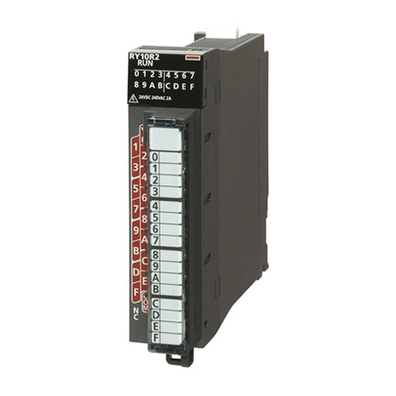
Page 21: Chapter 1 Part Names
PART NAMES This section describes the names of each part of the RJ71PB91V. Name Description RUN LED Indicates the operating status of the module. On: Normal operation Flashing: During initialization of the flash ROM or during self-diagnostics test Off: Error ( MELSEC iQ-R PROFIBUS-DP Module User's Manual (Application)) ERR LED Indicates the error status of the module. - Page 22 MEMO 1 PART NAMES...
-
Page 23: Chapter 2 Specifications
SPECIFICATIONS Performance Specifications The following table lists the performance specifications of the RJ71PB91V. Item Description PROFIBUS-DP station type DP-Master (Class 1) DP-Slave Transmis Electrical standard and characteristics Compliant with EIA-RS485 sion Medium Shielded twisted pair cable ( Page 32 Wiring for PROFIBUS cable) specifica Network configuration Bus topology (or tree topology when repeaters are used) - Page 24 MEMO 2 SPECIFICATIONS 2.1 Performance Specifications...
-
Page 25: Chapter 3 Function List
FUNCTION LIST The following table lists the functions of the RJ71PB91V. For details on the functions and constraints of the redundant system, refer to the following. MELSEC iQ-R PROFIBUS-DP Module User's Manual (Application) Functions of DP-Master Function Description Version of PROFIBUS-DP I/O data exchange function Exchanges I/O data between the DP-Master and the DP-Slave. - Page 26 MEMO 3 FUNCTION LIST 3.2 Functions of DP-Slave...
-
Page 27: Chapter 4 Procedures Before Operation
PROCEDURES BEFORE OPERATION This chapter describes the procedures before operation. Self-diagnostics test Turn on the power and perform the self-diagnostics test on the RJ71PB91V alone. ( MELSEC iQ-R PROFIBUS-DP Module User's Manual (Application)) When no errors are detected, the LEDs and the relevant buffer memory areas behave as follows. •... - Page 28 MEMO 4 PROCEDURES BEFORE OPERATION...
-
Page 29: Chapter 5 System Configuration
SYSTEM CONFIGURATION For the configuration of the MELSEC iQ-R series system and the types, number, installation, and wiring of modules connectable to the CPU module, refer to the following. MELSEC iQ-R Module Configuration Manual Configuration of PROFIBUS-DP network This section describes the basic configuration of the PROFIBUS-DP network using the RJ71PB91V as the DP-Master or a DP-Slave. - Page 30 Maximum configuration of network (using one repeater) Using a repeater, two segments can be linked to one network. However, because repeaters are counted as modules for both segments, the number of connectable modules of the entire network is changed as follows. DP-Master: 1 (2 in the redundant system) DP-Slave: 61 (60 in the redundant system) Repeater: 1...
- Page 31 Maximum configuration of network (using three repeaters) When three repeaters are used, DP-Masters and DP-Slaves can be connected within the FDL address setting range (0 to 125), and the number of connectable modules of the entire network is changed as follows. DP-Master: 1 (2 in the redundant system) DP-Slave: 125 (124 in the redundant system) Repeater: 4 (maximum of 3 repeaters between the DP-Master and a DP-Slave)
- Page 32 Multi-master system Multiple DP-Masters having different FDL addresses can be connected in one network. Maximum of 123 DP-Slaves can be connected using three DP-Masters as follows. DP-Master: 3 DP-Slave: 123 Repeater: 4 RJ71PB91V RJ71PB91V RJ71PB91V No.1 No.2 No.3 (1) No.0 (2) No.4 (3) No.5 (3) No.34...
-
Page 33: Available Software Packages
Available Software Packages An engineering tool and a configuration tool are required to configure the RJ71PB91V. Item Software Supported version Setting Engineering tool GX Works3 Version 1.042U or later When operating as the DP-Master Version 1.045X or later When operating as the DP-Slave Version 1.047Z or later •... -
Page 34: Chapter 6 Wiring
WIRING Connectors Wiring for PROFIBUS cable This section describes the pin assignment of the PROFIBUS-DP interface connector of the RJ71PB91V, wiring specifications of the PROFIBUS cable, and the bus terminator. ■Pin assignment of the PROFIBUS-DP interface connector The following table shows the pin assignment of the PROFIBUS-DP interface connector (D-sub 9-pin female connector). Pin assignment Signal code Name... - Page 35 Precautions To make full use of the functions of the RJ71PB91V and to configure a highly reliable system, the external wiring should be resistant to noise. The following are precautions for the external wiring of the RJ71PB91V. • Do not route the communication cable of the RJ71PB91V near the main circuit, power cable, or load cable other than that of the programmable controller.
-
Page 36: Wiring Products
Wiring Products PROFIBUS devices such as PROFIBUS cables and connectors should be prepared by users. For details on PROFIBUS devices, refer to the following. • PI: www.profibus.com PROFIBUS cable Use PROFIBUS cables that satisfy the following specifications (compliant with TypeA (IEC 61158-2)). Item Specifications Applicable cable... -
Page 37: Chapter 7 Communication Example
COMMUNICATION EXAMPLE Communication example of I/O data exchanges This section describes an example of I/O data exchanges between the DP-Master and DP-Slaves (with the refresh settings enabled). System configuration example The following system configuration is used in this section. System configuration RJ71PB91V(S) No.1 RJ71PB91V(S) No.3 RJ71PB91V No.0... - Page 38 ■I/O data assignment between DP-Master and DP-Slave (FDL address 1) No.0 RJ71PB91V No.1 RJ71PB91V(S) R04CPU RX40C7 Un\G0~Un\G191 Un\G0 RY41NT2P Un\G9 Un\G10 Un\G15 RH42C4NT2P Un\G16 Un\G191 Y11F Un\G256~Un\G447 RY40NT5P Un\G256 RX40NC6B Un\G265 Un\G266 Un\G271 Un\G272 Un\G447 X11F RY40NT5P (1) Output data area (for mode 3) on the DP-Master. Output data is sent to (2) by the I/O data exchange function. (2) Output receive area (Un\G0 to Un\G9) on the DP-Slave.
-
Page 39: Settings For Dp-Master
Settings for DP-Master Connect the engineering tool to the CPU module of the DP-Master, and set the parameters. Creating a new project Set the CPU module as follows. [Project] [New] Click the [Setting Change] button and set the [Module Label] to [Use]. Click the [OK] button to add the module labels of the CPU module. - Page 40 PROFIBUS module setting Start PROFIBUS Configuration Tool from the engineering tool. [Navigation window] [Parameter] [Module Information] [RJ71PB91V] [PROFIBUS Module Setting] Add the DP-Slave to the project. [Navigation window] [Parameter] [Module Information] [RJ71PB91V] [PROFIBUS Module Setting] [Global GSD Database] tab ...
- Page 41 Set the items in the "Slave Settings" window as follows. [Navigation window] [Parameter] [Module Information] [RJ71PB91V] [PROFIBUS Module Setting] Target DP-Slave Right-click [Slave Settings] • DP-Slave (FDL address 1) 7 COMMUNICATION EXAMPLE 7.1 Communication example of I/O data exchanges...
- Page 42 Set the items in "Master Settings" as follows. [Navigation window] [Parameter] [Module Information] [RJ71PB91V] [PROFIBUS Module Setting] [I/O no.:0x0000/FDL:0 'RJ71PB91V'] Right-click [Master Settings] 7 COMMUNICATION EXAMPLE 7.1 Communication example of I/O data exchanges...
- Page 43 Click the [Next] button in the "Master Settings" window, and set the items in "CPU Device Access" as follows. Click the [Finish] button to exit the "Master Settings" window. 7 COMMUNICATION EXAMPLE 7.1 Communication example of I/O data exchanges...
- Page 44 Update of PROFIBUS labels This function creates and updates the structures used for global labels and module function blocks by enabling the refresh settings. Click "Update PROFIBUS Label". [Navigation window] [Parameter] [Module Information] [RJ71PB91V] [PROFIBUS Module Setting] [PROFIBUS Configurator Tasks] Convert some program codes or all program codes.
-
Page 45: Settings For Dp-Slaves
Settings for DP-Slaves Set for DP-Slaves that configure the PROFIBUS-DP network. For DP-Slaves that use the RJ71PB91V, connect the engineering tool to the CPU module, and set the parameters as follows. Set the same parameters to FDL address 1 and FDL address 3. For setting DP-Slaves that use the module other than the RJ71PB91V, refer to the manual for the module used. - Page 46 Set the items in "Refresh Setting" as follows. [Navigation window] [Parameter] [Module Information] [RJ71PB91V(S)] [Refresh Setting] Write the set parameters to the CPU module or an SD memory card in the CPU module. Then reset the CPU module or power off and on the system.
-
Page 47: Checking The Network Status
Checking the network status Communications are performed normally if the status of LEDs and bits corresponding to the relevant buffer memory areas are as follows after the program execution. • LED on DP-Master Name Status RUN LED ERR LED BF LED •... -
Page 48: Program Example
Program example When the DP-Master starts I/O data exchanges, the DP-Slave automatically starts receiving the output data. However, sending input data from the DP-Slave must be instructed from a program. • DP-Master (FDL address 0) Classificatio Label name Description Device Module label RCPU.stSM.bAfter_RUN1_Scan_ON After RUN, ON for 1 scan only... - Page 49 7 COMMUNICATION EXAMPLE 7.1 Communication example of I/O data exchanges...
- Page 50 7 COMMUNICATION EXAMPLE 7.1 Communication example of I/O data exchanges...
- Page 51 ■Initialization and temporarily reserved station specification (0) Turn on Initialization command (M400) at the startup. (2) Set 'Diagnostic information invalid setting area' (U0\G2080), 'Diagnostic information non-notification time setting area' (U0\G2084), and 'Temporarily reserved station specification request area' on the third device (U0\G23608.2). ■Start of I/O data exchanges (20)Turn on Condition to write to the output data (first word)_ET200S (X30), Condition to write to the output data (first word)_91V (X31), and 'Data exchange start request signal' (Y0).
- Page 52 The following is an example of a program to send input data from the DP-Slave during I/O data exchanges. • DP-Slave (FDL address 1) Classificatio Label name Description Device Module label RPB91V_S_1.bSts_ModuleWatchdogTimerError Module watchdog timer error signal RPB91V_S_1.bSts_DataExchProc During data exchange RPB91V_S_1.bSts_ModuleReady Module ready RPB91V_S_1.bSet_InputSendAreaRefreshDirective...
-
Page 53: Appendix
APPENDIX Appendix 1 External Dimensions This section describes the external dimensions of the RJ71PB91V. 27.8 (Unit: mm) APPX Appendix 1 External Dimensions... -
Page 54: Index
INDEX Acquisition of diagnostic information and extended ....23 diagnostic information ... . . 23 Acyclic communication function . - Page 55 MEMO...
-
Page 56: Revisions
Japanese manual number: SH-081854-E This manual confers no industrial property rights or any rights of any other kind, nor does it confer any patent licenses. Mitsubishi Electric Corporation cannot be held responsible for any problems involving industrial property rights which may occur as a result of using the contents noted in this manual. -
Page 57: Warranty
WARRANTY Please confirm the following product warranty details before using this product. 1. Gratis Warranty Term and Gratis Warranty Range If any faults or defects (hereinafter "Failure") found to be the responsibility of Mitsubishi occurs during use of the product within the gratis warranty term, the product shall be repaired at no cost via the sales representative or Mitsubishi Service Company. -
Page 58: Trademarks
TRADEMARKS The company names, system names and product names mentioned in this manual are either registered trademarks or trademarks of their respective companies. In some cases, trademark symbols such as ' ' or ' ' are not specified in this manual. SH(NA)-081855ENG-E... - Page 60 SH(NA)-081855ENG-E(2010)MEE MODEL: RJ71PB91V-U-IN-E MODEL CODE: 13JX79 HEAD OFFICE : TOKYO BUILDING, 2-7-3 MARUNOUCHI, CHIYODA-KU, TOKYO 100-8310, JAPAN NAGOYA WORKS : 1-14 , YADA-MINAMI 5-CHOME , HIGASHI-KU, NAGOYA , JAPAN When exported from Japan, this manual does not require application to the Ministry of Economy, Trade and Industry for service transaction permission.