Mitsubishi Electric MELSEC iQ-R Series User Manual
Gp-ib interface module
Hide thumbs
Also See for MELSEC iQ-R Series:
- Programming manual (2110 pages) ,
- User manual (760 pages) ,
- Reference manual (498 pages)
Table of Contents
Quick Links
Table of Contents

Related Manuals for Mitsubishi Electric MELSEC iQ-R Series


Summary of Contents for Mitsubishi Electric MELSEC iQ-R Series
- Page 1 MELSEC iQ-R GP-IB Interface Module User's Manual (Startup) -RJ71GB91...
-
Page 3: Safety Precautions
SAFETY PRECAUTIONS (Read these precautions before using this product.) Before using this product, please read this manual and the relevant manuals carefully and pay full attention to safety to handle the product correctly. The precautions given in this manual are concerned with this product only. For the safety precautions of the programmable controller system, refer to the MELSEC iQ-R Module Configuration Manual. - Page 4 [Design Precautions] WARNING ● Configure safety circuits external to the programmable controller to ensure that the entire system operates safely even when a fault occurs in the external power supply or the programmable controller. Failure to do so may result in an accident due to an incorrect output or malfunction. (1) Emergency stop circuits, protection circuits, and protective interlock circuits for conflicting operations (such as forward/reverse rotations or upper/lower limit positioning) must be configured external to the programmable controller.
- Page 5 [Design Precautions] WARNING ● For the operating status of each station after a communication failure, refer to manuals for the network used. For the manuals, please consult your local Mitsubishi representative. Incorrect output or malfunction due to a communication failure may result in an accident. ●...
- Page 6 [Design Precautions] CAUTION ● Do not install the control lines or communication cables together with the main circuit lines or power cables. Doing so may result in malfunction due to electromagnetic interference. Keep a distance of 100mm or more between those cables. ●...
- Page 7 [Installation Precautions] WARNING ● Shut off the external power supply (all phases) used in the system before mounting or removing the module. Failure to do so may result in electric shock or cause the module to fail or malfunction. [Installation Precautions] CAUTION ●...
- Page 8 [Wiring Precautions] CAUTION ● Individually ground the FG and LG terminals of the programmable controller with a ground resistance of 100 ohms or less. Failure to do so may result in electric shock or malfunction. ● Use applicable solderless terminals and tighten them within the specified torque range. If any spade solderless terminal is used, it may be disconnected when the terminal screw comes loose, resulting in failure.
- Page 9 [Startup and Maintenance Precautions] WARNING ● Do not touch any terminal while power is on. Doing so will cause electric shock or malfunction. ● Correctly connect the battery connector. Do not charge, disassemble, heat, short-circuit, solder, or throw the battery into the fire. Also, do not expose it to liquid or strong shock. Doing so will cause the battery to produce heat, explode, ignite, or leak, resulting in injury and fire.
- Page 10 [Startup and Maintenance Precautions] CAUTION ● After the first use of the product, do not insert/remove the SD memory card to/from the CPU module more than 500 times. Exceeding the limit may cause malfunction. ● Do not touch the metal terminals on the back side of the SD memory card. Doing so may cause malfunction or failure of the module.
- Page 11 [Disposal Precautions] CAUTION ● When disposing of this product, treat it as industrial waste. ● When disposing of batteries, separate them from other wastes according to the local regulations. For details on battery regulations in EU member states, refer to the MELSEC iQ-R Module Configuration Manual.
-
Page 12: Conditions Of Use For The Product
Notwithstanding the above restrictions, Mitsubishi Electric may in its sole discretion, authorize use of the PRODUCT in one or more of the Prohibited Applications, provided that the usage of the PRODUCT is limited only for the specific applications agreed to by Mitsubishi Electric and provided further that no special quality assurance or fail-safe, redundant or other safety features which exceed the general specifications of the PRODUCTs are required. -
Page 13: Compliance With Emc And Low Voltage Directives
COMPLIANCE WITH EMC AND LOW VOLTAGE DIRECTIVES Method of ensuring compliance To ensure that Mitsubishi programmable controllers maintain EMC and Low Voltage Directives when incorporated into other machinery or equipment, certain measures may be necessary. Please refer to one of the following manuals. •... - Page 14 MEMO...
-
Page 15: Table Of Contents
CONTENTS SAFETY PRECAUTIONS ..............1 CONDITIONS OF USE FOR THE PRODUCT . -
Page 16: Relevant Manuals
• Installation For details, refer to the following. MELSEC iQ-R Module Configuration Manual e-Manual refers to the Mitsubishi Electric FA electronic book manuals that can be browsed using a dedicated tool. e-Manual has the following features: • Required information can be cross-searched in multiple manuals. -
Page 17: Terms
A generic term for functions specific to each device, such as a measurement function of voltage or frequency GP-IB interface module An abbreviation for the MELSEC iQ-R series GP-IB interface module Interface message A generic term for messages used by the controller to control the other devices. -
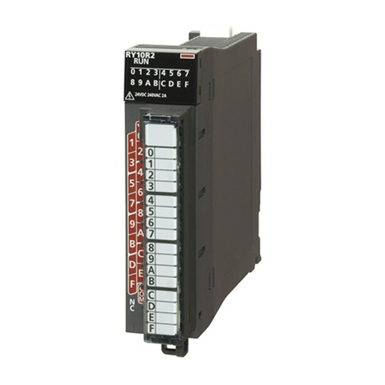
Page 18: Chapter 1 Part Names
PART NAMES This chapter describes the part names of the GP-IB interface module. Name Description RUN LED Indicates the operating status of the GP-IB interface module. On: Normal operation Off: 5V power supply interrupted, watchdog timer error occurred ERR LED Indicates the error status of the GP-IB interface module. - Page 19 MEMO 1 PART NAMES...
-
Page 20: Chapter 2 Specifications
SPECIFICATIONS This chapter describes the performance specifications. Performance Specifications The following table lists the performance specifications of the GP-IB interface module. RJ71GB91 Item Specifications GP-IB interface 1 port Transmission method 8 bits parallel transmission Communication mode Half-duplex Interface IEEE488.1 compliant Handshake method 3-wire handshake Network topology... - Page 21 MEMO 2 SPECIFICATIONS 2.1 Performance Specifications...
-
Page 22: Chapter 3 Function Lists
FUNCTION LISTS This chapter shows the function lists of the GP-IB interface module. For details on the functions, refer to the following. MELSEC iQ-R GP-IB Interface Module User's Manual (Application) Item Master mode Slave mode Interface message transmission The GP-IB interface module sends interface messages to ... - Page 23 GP-IB interface functions The following table lists GP-IB interface functions used in master mode or in slave mode. Function Master mode Slave mode SH (source handshake) Available (transmission function) Available (transmission function) AH (acceptor handshake) Available (reception function) Available (reception function) C (controller) •...
-
Page 24: Chapter 4 Procedures Before Operation
PROCEDURES BEFORE OPERATION This chapter describes the procedures before operation. Mounting a module Mount the GP-IB interface module in any desired configuration. Page 24 SYSTEM CONFIGURATION Wiring Wire the GP-IB interface module to external devices. Page 27 External Wiring Adding a module Add the GP-IB interface module to a module configuration by using the engineering tool. - Page 25 MEMO 4 PROCEDURES BEFORE OPERATION...
-
Page 26: Chapter 5 System Configuration
SYSTEM CONFIGURATION For system configurations using the MELSEC iQ-R series modules, CPU modules that can be connected with the GP-IB interface module, and the number of mountable GP-IB interface modules, refer to the following. MELSEC iQ-R Module Configuration Manual Network Topology Use either of following network topologies when connecting the GP-IB interface module to GP-IB devices. - Page 27 Star topology (1) Controller (2) GP-IB interface module (3) GP-IB cable (4) GP-IB device Precautions For precautions on the connections, refer to the following. Page 26 Precautions 5 SYSTEM CONFIGURATION 5.1 Network Topology...
-
Page 28: Chapter 6 Wiring
WIRING This chapter describes wiring of the GP-IB interface module. Wiring Procedures The following shows how to connect and remove the GP-IB cable. Connection Insert and connect the wired GP-IB cable horizontally to the slot of the GP-IB interface module. Fix the cable with GP-IB connector screws (M3.5) at two locations. -
Page 29: External Wiring
External Wiring The following shows the signal layout of the GP-IB connector. Pin layout (viewed from the Pin number Signal name Pin number Signal name front of the module) DIO1 DIO5 DIO2 DIO6 DIO3 DIO7 DIO4 DIO8 NRFD NDAC Logic GND 6 WIRING 6.3 External Wiring... -
Page 30: Chapter 7 Communication Examples
COMMUNICATION EXAMPLES This chapter describes the programming procedure and program examples of the GP-IB interface module. Programming Procedure Take the following steps to create programs for running the GP-IB interface module: Set parameters. Page 30 Parameter settings Create programs. Page 38 Program examples 7 COMMUNICATION EXAMPLES 7.1 Programming Procedure... -
Page 31: Program Examples
Program Examples System configuration The following figure is an example of the system configuration. (2) (3) (2) (5) (1) Power supply module (R61P) (2) CPU module (R04CPU) (3) GP-IB interface module (master mode) (RJ71GB91) (4) GP-IB cable (5) GP-IB interface module (slave mode) (RJ71GB91): Device 1 (device address 1) (6) GP-IB device: Device 2 (device address 5) 7 COMMUNICATION EXAMPLES 7.2 Program Examples... -
Page 32: Parameter Settings
Parameter settings Module settings of the GP-IB interface module (master mode) Connect the engineering tool to the CPU module on master mode side and set parameters. Create the project with the following settings. [Project] [New] Click the [Setting Change] button and set the module to use the module labels. Click the [OK] button in the following window to add the module labels of the CPU module. - Page 33 Set the GP-IB interface module as follows. [Navigation window] [Parameter] [Module Information] Right-click [Add New Module] The GP-IB interface module is set to master mode by setting "Module Name" to "RJ71GB91(M)". Set the window as follows to add the module labels of the GP-IB interface module. 7 COMMUNICATION EXAMPLES 7.2 Program Examples...
- Page 34 Parameter settings of the GP-IB interface module (master mode) Set "Basic settings" of the module parameters of the GP-IB interface module as shown below. [Navigation window] [Parameter] [Module Information] Module model name [Basic settings] Set "Application settings" of the module parameters of the GP-IB interface module as shown below. [Navigation window] ...
- Page 35 Module settings of the GP-IB interface module (slave mode) Connect the engineering tool to the CPU module on slave mode side and set parameters. Create the project with the following settings. [Project] [New] Click the [Setting Change] button and set the module to use the module labels. Click the [OK] button in the following window to add the module labels of the CPU module.
- Page 36 Set the GP-IB interface module as follows. [Navigation window] [Parameter] [Module Information] Right-click [Add New Module] The GP-IB interface module is set to slave mode by setting "Module Name" to "RJ71GB91(S)". Set the window as follows to add the module labels of the GP-IB interface module. 7 COMMUNICATION EXAMPLES 7.2 Program Examples...
- Page 37 Parameter settings of the GP-IB interface module (slave mode) Set "Basic settings" of the module parameters of the GP-IB interface module as shown below. [Navigation window] [Parameter] [Module Information] Module model name [Basic settings] Write the set parameters to the CPU module. Then, reset the CPU module or power off and on the system. [Online] ...
-
Page 38: Label Settings
Label settings The engineering tool provides functions that support the creation of programs. The following tables list the module labels and global labels used for the program examples in this section. The settings of module labels do not need to be changed. For details on the global labels, refer to the following. ... - Page 39 Classification Label name Description Device Labels to be defined Define global labels as shown below: • Master mode • Slave mode 7 COMMUNICATION EXAMPLES 7.2 Program Examples...
-
Page 40: Program Examples
Program examples Precautions In the programs provided in this section, if the CPU module is changed to STOP while each request is not yet complete, a device used for the request or command, such as 'DataTransmissionCommand_S' (M10), may not be reset properly even after the CPU module is changed to RUN again. - Page 41 Program examples in master mode ■Interface message transmission (destination not specified) The following example is a program for interface clear. For the program of turning on 'Interface message transmission request' (Y2), refer to the following. Page 42 Program common to interface message transmission (0) The IFC signal is sent by turning on 'InterfaceClearCommand' (M0).
- Page 42 ■Interface message transmission (destination specified) The following example is a program for device trigger. For the program of turning on 'Interface message transmission request' (Y2), refer to the following. Page 42 Program common to interface message transmission (0) The following operations are performed by turning on 'TriggerCommand' (M1): the GP-IB interface module (slave mode) and the GP-IB device are specified as the interface message destination;...
- Page 43 ■Processing at service request reception The following example is a program for serial poll, which is performed at service request reception. For the program of turning on 'Interface message transmission request' (Y2), refer to the following. Page 42 Program common to interface message transmission (0) At service request reception, the following operations are performed by turning on 'SerialPollCommand' (M4): all devices are specified as the interface message destination;...
- Page 44 ■Program common to interface message transmission The following example is a part of program that is used for all types of interface message transmission. (0) Turn on 'Interface message transmission request' when a relay of each interface message turns on. 7 COMMUNICATION EXAMPLES 7.2 Program Examples...
- Page 45 ■Data transmission The following example is a program for data transmission. (0) Data of 128 bytes are sent to the GP-IB interface module (slave mode) and the GP-IB device by turning on 'DataTransmissionCommand_M' (M2). 7 COMMUNICATION EXAMPLES 7.2 Program Examples...
- Page 46 ■Data reception The following example is a program for data reception. 7 COMMUNICATION EXAMPLES 7.2 Program Examples...
- Page 47 (0) The GP-IB interface module (master mode) and the GP-IB device receive data sent from the GP-IB interface module (slave mode) by turning on 'DataReceptionCommand' (M3). 7 COMMUNICATION EXAMPLES 7.2 Program Examples...
- Page 48 ■Error clear processing The following example is a program for error clear processing. (0) When an error has occurred, the error is cleared by turning on 'ErrorClearCommand' (M5). 7 COMMUNICATION EXAMPLES 7.2 Program Examples...
- Page 49 Program examples in slave mode ■Device clear The following example is a program for device clear. (0) Turn on 'DeviceClearProcessingCommand' (M40) when the DCL command or the SDC command sent from the controller has been received. The device clear is complete by performing the process required for the system and turning on 'DeviceClearProcessingCompletion' (M50). 7 COMMUNICATION EXAMPLES 7.2 Program Examples...
- Page 50 ■Device trigger The following example is a program for device trigger. (0) Turn on 'DeviceTriggerProcessingCommand' (M41) when the GET command sent from the controller has been received. The device trigger is complete by performing the process required for the system and turning on 'DeviceTriggerProcessingCompletion' (M51). 7 COMMUNICATION EXAMPLES 7.2 Program Examples...
- Page 51 ■Data transmission The following example is a program for data transmission. (0) Data of 16 bytes are sent by turning on 'DataTransmissionCommand_S' (M10). Turn on 'DataTransmissionCompletion_S' (202) when data transmission is complete after the own device being specified as the talker by the controller. 7 COMMUNICATION EXAMPLES 7.2 Program Examples...
- Page 52 ■Data reception The following example is a program for data reception. (0) Received data are transferred to the area of 'ReceivedDataHead_S' (D14000) and later when the end of data reception has been detected after the own device being specified as a listener by the controller. 7 COMMUNICATION EXAMPLES 7.2 Program Examples...
- Page 53 ■Service request The following example is a program to notify the controller that a service request has been issued when an error occurs in the system (when 'DeviceError' (M11) turns on). (0) The following operations are performed by turning on 'DeviceError' (M11): a status byte (H1), which is sent back to the controller at the reception of serial poll, is set;...
-
Page 54: Appendix
APPENDIX Appendix 1 External Dimensions This chapter shows the external dimensions of the GP-IB interface module. 27.8 (Unit: mm) APPX Appendix 1 External Dimensions... - Page 55 MEMO APPX Appendix 1 External Dimensions...
-
Page 56: Index
INDEX ......16 ERR LED ..... . 16 GP-IB address LED . - Page 57 MEMO...
-
Page 58: Revisions
Japanese manual number: SH-082377-A This manual confers no industrial property rights or any rights of any other kind, nor does it confer any patent licenses. Mitsubishi Electric Corporation cannot be held responsible for any problems involving industrial property rights which may occur as a result of using the contents noted in this manual. -
Page 59: Warranty
WARRANTY Please confirm the following product warranty details before using this product. 1. Gratis Warranty Term and Gratis Warranty Range If any faults or defects (hereinafter "Failure") found to be the responsibility of Mitsubishi occurs during use of the product within the gratis warranty term, the product shall be repaired at no cost via the sales representative or Mitsubishi Service Company. -
Page 60: Trademarks
TRADEMARKS The company names, system names and product names mentioned in this manual are either registered trademarks or trademarks of their respective companies. In some cases, trademark symbols such as ' ' or ' ' are not specified in this manual. SH(NA)-082378ENG-A... - Page 62 SH(NA)-082378ENG-A(2101)MEE MODEL: RJ71GB91-U-IN-E MODEL CODE: 13JX4F HEAD OFFICE : TOKYO BUILDING, 2-7-3 MARUNOUCHI, CHIYODA-KU, TOKYO 100-8310, JAPAN NAGOYA WORKS : 1-14 , YADA-MINAMI 5-CHOME , HIGASHI-KU, NAGOYA , JAPAN When exported from Japan, this manual does not require application to the Ministry of Economy, Trade and Industry for service transaction permission.