Mitsubishi Electric MELSEC iQ-R Series User Manual
Process cpu module
Hide thumbs
Also See for MELSEC iQ-R Series:
- Programming manual (2110 pages) ,
- User manual (682 pages) ,
- Reference manual (498 pages)

Related Manuals for Mitsubishi Electric MELSEC iQ-R Series


Summary of Contents for Mitsubishi Electric MELSEC iQ-R Series
- Page 1 MELSEC iQ-R Process CPU Module User's Manual -R08PCPU -R16PCPU -R32PCPU -R120PCPU -R6RFM...
-
Page 3: Safety Precautions
(Read these precautions before using this product.) Before using MELSEC iQ-R series programmable controllers, please read the manuals for the product and the relevant manuals introduced in those manuals carefully, and pay full attention to safety to handle the product correctly. If products are used in a different way from that specified by manufacturers, the protection function of the products may not work properly. - Page 4 [Design Precautions] WARNING ● Configure safety circuits external to the programmable controller to ensure that the entire system operates safely even when a fault occurs in the external power supply or the programmable controller. Failure to do so may result in an accident due to an incorrect output or malfunction. (1) Emergency stop circuits, protection circuits, and protective interlock circuits for conflicting operations (such as forward/reverse rotations or upper/lower limit positioning) must be configured external to the programmable controller.
- Page 5 [Design Precautions] WARNING ● Especially, when a remote programmable controller is controlled by an external device, immediate action cannot be taken if a problem occurs in the programmable controller due to a communication failure. To prevent this, configure an interlock circuit in the program, and determine corrective actions to be taken between the external device and CPU module in case of a communication failure.
- Page 6 [Design Precautions] CAUTION ● Do not install the control lines or communication cables together with the main circuit lines or power cables. Doing so may result in malfunction due to electromagnetic interference. Keep a distance of 100mm or more between those cables. ●...
- Page 7 [Installation Precautions] WARNING ● Shut off the external power supply (all phases) used in the system before mounting or removing the module. Failure to do so may result in electric shock or cause the module to fail or malfunction. [Installation Precautions] CAUTION ●...
- Page 8 Directly touching any conductive parts of the connectors while power is on may result in electric shock. *1 For details, please consult your local Mitsubishi Electric representative. [Wiring Precautions] CAUTION ● Individually ground the FG and LG terminals of the programmable controller with a ground resistance of 100 ohms or less.
- Page 9 [Wiring Precautions] CAUTION ● Prevent foreign matter such as dust or wire chips from entering the module. Such foreign matter can cause a fire, failure, or malfunction. ● When a protective film is attached to the top of the module, remove it before system operation. If not, inadequate heat dissipation of the module may cause a fire, failure, or malfunction.
- Page 10 [Startup and Maintenance Precautions] CAUTION ● When connecting an external device with a CPU module or intelligent function module to modify data of a running programmable controller, configure an interlock circuit in the program to ensure that the entire system will always operate safely. For other forms of control (such as program modification, parameter change, forced output, or operating status change) of a running programmable controller, read the relevant manuals carefully and ensure that the operation is safe before proceeding.
- Page 11 [Startup and Maintenance Precautions] CAUTION ● Startup and maintenance of a control panel must be performed by qualified maintenance personnel with knowledge of protection against electric shock. Lock the control panel so that only qualified maintenance personnel can operate it. ●...
- Page 12 Cautions When Using Mitsubishi Programmable Controllers or GOTs Connected to a Personal Computer With the RS-232/USB Interface (FA-A-0298) When the USB cable used is the GT09-C30USB-5P manufactured by Mitsubishi Electric, specific measures are not required to connect the AC-powered personal computer to the module. However, note that the signal ground (SG) is common for the module and its USB interface.
-
Page 13: Introduction
Before using this product, please read this manual and the relevant manuals carefully and develop familiarity with the functions and performance of the MELSEC iQ-R series programmable controller to handle the product correctly. When applying the program examples provided in this manual to an actual system, ensure the applicability and confirm that it will not cause system control problems. -
Page 14: Table Of Contents
CONTENTS SAFETY PRECAUTIONS ..............1 INTRODUCTION . - Page 15 Precautions when the data logging function is used ..........61 Wiring .
- Page 16 Standby type program ..............111 Execution type change .
- Page 17 PART 6 FUNCTIONS CHAPTER 12 FUNCTION LIST CHAPTER 13 CLOCK FUNCTION 13.1 Time Setting ................185 Clock data .
- Page 18 16.4 Remote RESET ............... . 223 Enabling remote RESET .
- Page 19 20.12 SD Memory Card Replacement ............294 20.13 SD Memory Card Life When the Data Logging Function Is Used .
- Page 20 CHAPTER 25 ROUTING SETTING 25.1 Setting Method............... . . 367 25.2 Setting Example.
- Page 21 Precautions on writing data from GOT or external devices ........445 Precautions on outputting in the middle of the scan .
- Page 22 27.11 Nesting (N) ................483 27.12 Pointer (P) .
- Page 23 CHAPTER 32 CONSTANTS 32.1 Decimal Constant (K) ..............526 32.2 Hexadecimal Constant (H) .
- Page 24 CHAPTER 36 ERROR CODES 36.1 Error Code System ..............550 36.2 Operation When an Error Occurs .
- Page 25 Online module change function ............. 700 System information .
-
Page 26: Relevant Manuals
This manual does not include information on the module function blocks. For details, refer to the Function Block Reference for the module used. e-Manual refers to the Mitsubishi Electric FA electronic book manuals that can be browsed using a dedicated tool. -
Page 27: Terms
TERMS Unless otherwise specified, this manual uses the following terms. Term Description Backup mode A mode to continue operation in a redundant system by switching the standby system to the control system when an error occurs in the control system. Buffer memory Memory in an intelligent function module for storing data such as setting values and monitored values. -
Page 28: Generic Terms And Abbreviations
• CC-Link IE Field Network master/local module • MELSECNET/H network module • MELSECNET/10 network module Power supply module A MELSEC iQ-R series power supply module Process CPU R08PCPU, R16PCPU, R32PCPU, R120PCPU Process CPU (process mode) A Process CPU operating in process mode. -
Page 29: Part 1 Part Names
PART 1 PART NAMES This part consists of the following chapters. 1 CPU MODULE 2 EXTENDED SRAM CASSETTE 3 REDUNDANT FUNCTION MODULE... -
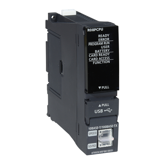
Page 30: Chapter 1 Cpu Module
CPU MODULE This chapter describes the part names of the CPU module. The R08PCPU is used as an example. (13) (12) (11) (14) (15) (10) (21) (19) (18) (20) (17) (16) 1 CPU MODULE... - Page 31 Name Description READY LED Indicates the operating status of the CPU module and the error level. ( Page 533 LED status of the CPU module) ERROR LED ● READY LED-ERROR LED status On-off: Normal operation On-on: Minor error On-flashing: Moderate error Flashing-on: Minor error (Changing module online) Flashing (every 2s)-off: Initial processing Flashing (every 400ms)-off: Changing module online...
- Page 32 Name Description (16) Battery A backup battery to hold clock data and to use the backup power function for the device/label memory (17) Battery connector pin A pin for connecting a lead wire of the battery (To save the battery, the lead wire is disconnected from the connector before shipment.) (18) Cassette cover A cover for the connector where an extended SRAM cassette is inserted (...
-
Page 33: Chapter 2 Extended Sram Cassette
EXTENDED SRAM CASSETTE This chapter describes the part names of the extended SRAM cassette. Name Description Tab for cassette insertion/removal The part that is held when an extended SRAM cassette is inserted or removed ( Page 39 Inserting or Removing an Extended SRAM Cassette) 2 EXTENDED SRAM CASSETTE... - Page 34 MEMO 2 EXTENDED SRAM CASSETTE...
-
Page 35: Chapter 3 Redundant Function Module
REDUNDANT FUNCTION MODULE This chapter describes the part names of the redundant function module. (10) (11) (12) (13) (14) Name Description RUN LED Indicates the operating status. On: Normal operation Flashing: Changing module online or executing a module communication test Off: Error (... - Page 36 Name Description (10) LINK LED Indicates the tracking communication status. On: Tracking communications being performed Off: Tracking communications not performed (11) L ERR LED Indicates the tracking communication error. On: Tracking communication error (one of the following) • A receive data is faulty (receive frame error). •...
-
Page 37: Part 2 Procedures Before Operation
PART 2 PROCEDURES BEFORE OPERATION This part consists of the following chapters. 4 START-UP PROCEDURE 5 PROCEDURE FOR STARTING UP A REDUNDANT SYSTEM... -
Page 38: Chapter 4 Start-Up Procedure
START-UP PROCEDURE This chapter describes the procedures before operation. Overview This section describes an outline of the procedure before operation for each CPU module. Procedure for process mode This section describes an outline of the procedure when using the Process CPU (process mode). The procedure for starting up a redundant system is partially different. - Page 39 Initializing the CPU module Initialize the CPU module using the engineering tool. ( Page 43 Initializing the CPU Module) Setting parameters The following table shows which parameters are required when changing the number of slots/the number of occupied points of a module, using an SD memory card, or using specific functions. When Required parameter Reference...
-
Page 40: Installing A Battery
Installing a Battery Install a battery to the CPU module. Installation procedure Q6BAT The connector plug of the Q6BAT is disconnected from the jack of the CPU module before shipment. To use the battery, connect the connector plug of the Q6BAT and the jack of the CPU module by following the procedure below. Open the battery cover located on the bottom of the CPU module. -
Page 41: Inserting Or Removing An Extended Sram Cassette
Inserting or Removing an Extended SRAM Cassette Insert an extended SRAM cassette to the CPU module as needed. Insertion procedure Insert an extended SRAM cassette while the programmable controller is powered off. Open the cassette cover (1) located on the side of the CPU module. -
Page 42: Inserting And Removing An Sd Memory Card
Inserting and Removing an SD Memory Card Insert an SD memory card to the CPU module as needed. Insertion procedure Check the direction and insert an SD memory card, following the procedure below. Insert an SD memory card (1) into the card slot until it clicks with the notched edge in the direction as illustrated. -
Page 43: Creating A Project
Creating a Project Activate the engineering tool and create a project. [Project] [New] Procedure Create a program, following the procedure below. The procedure is for the program described in ladder diagrams. Select "RCPU" in "Series", and the CPU module model to use in "Type". Then, select a programming language to use in the project in "Program". -
Page 44: Connecting A Personal Computer
Connecting a Personal Computer Connect a personal computer where an engineering tool has been installed to the CPU module. Procedure Connect a personal computer directly to the CPU module, following the procedure below. Connect a personal computer to the CPU module using a USB cable or Ethernet cable. -
Page 45: Initializing The Cpu Module
Initializing the CPU Module Initialize the CPU module. [Online] [CPU Memory Operation] Procedure Select "Data Memory" on the "Memory Management" window, and click the [Initialization] button. Select "File Storage Area", and click the [Initialization] button. After the initialization processing completes, click the [Close] button. - Page 46 When the engineering tool is not connected to the actual system Set parameters by configuring a system manually on the Module Configuration window of the engineering tool. Select a base unit on the Element Selection window, and drag and drop it to the Module Configuration window. Drag and drop modules to be used on the base unit placed.
- Page 47 Setting parameters from the Navigation window Set the following parameters from the Navigation window. ■System parameters These parameters need to be set from the Navigation window in the following cases: to change the number of slots on the base unit or the number of occupied points of the module; for a multiple CPU system; and for module synchronization operations.
-
Page 48: Programming
Programming Create a program. This section describes how to create a program using the following program example. Program example • When Start1 turns on, Timer1 starts counting, and Lamp1 turns on. • When the current value of Timer1 reaches 1000, Lamp1 turns off. •... -
Page 49: Inserting Program Elements
Inserting program elements Drag and drop required program elements to the ladder editor. [Navigation window] [Program] [Scan] [MAIN] [ProgPou] [ProgramBody] Procedure Insert a normally open contact of "Start1" in the program example, following the procedure below. Select a program element from the Element Selection window, and drag and drop (1) it to the desired position on the ladder editor. - Page 50 ■Inserting function blocks Insert function blocks, following the procedure below. Select a function block from the Element Selection window, and drag and drop it to the desired position on the ladder editor. The "FB Instance Name" window opens. Select the target label (global label or local label), and enter an instance name.
-
Page 51: Inserting Pous By Key Input
Inserting POUs by key input POUs can be inserted by key input. Procedure Inserting a normally open contact of "Start1" in the program example, following the procedure below. Click the insertion position on the ladder editor, and press . Enter the name, "Start", in the entry field (1). Select "Start1" from the displayed list (2). -
Page 52: Converting The Program
4.10 Converting the Program Determine the input ladder blocks. Procedure Select [Convert] [Convert] on the menu bar. When the conversion processing completes and the input ladder blocks are determined, the color of those ladder blocks changes from gray to white. 4.11 Saving the Project Save the created project. -
Page 53: Resetting The Cpu Module
4.13 Resetting the CPU Module Reset the CPU module using the RUN/STOP/RESET switch located on the front of the CPU module. Procedure Set the RUN/STOP/RESET switch (1) to the RESET position for a second or longer. Check that the ERROR LED (2) flashes for several times and turns off. -
Page 54: Executing The Program
4.14 Executing the Program Execute the program written to the programmable controller by using the RUN/STOP/RESET switch. Procedure Set the RUN/STOP/RESET switch (1) to the RUN position. Check that the PROGRAM RUN LED (P RUN) (2) turns on. 4 START-UP PROCEDURE 4.14 Executing the Program... -
Page 55: Monitoring The Program
4.15 Monitoring the Program Monitor the program operation using the engineering tool. Monitoring on the monitor status bar For the monitor status bar, refer to the following. GX Works3 Operating Manual Monitoring on the ladder editor The on/off states of contacts and coils and the current values of word devices and labels can be monitored on the ladder editor. -
Page 56: Chapter 5 Procedure For Starting Up A Redundant System
PROCEDURE FOR STARTING UP A REDUNDANT SYSTEM This chapter describes the procedures for starting up a redundant system starting from the start-up procedure of CPU modules to execution of programs. Overview There are two ways to start up a redundant system. Start-up procedure Description Starting up both systems... - Page 57 Setting parameters Set system parameters, CPU parameters, and module parameters. ( Page 43 Setting Parameters) • To execute the functions that access the SD memory card, set memory card parameters. • When an intelligent function module is used in the system, set intelligent function module parameters. Users can set system parameters by loading the actual system configuration to the "Module Configuration"...
- Page 58 Checking the connection of the extension cables When extension base units at extension level 2 and later are connected, check that the following LEDs are turned on. • CONNECT LED for the extension cable connected to the extension base unit •...
-
Page 59: Starting Up The Systems One By One
Starting up the systems one by one To debug a program with only one system before operation, start up the control system. To start up the control system for a purpose other than debugging a program, start up the standby system to build a redundant system. - Page 60 Creating a program Create a program with the engineering tool. After creating the program, convert the program and save the project. ( Page 46 Programming) Writing the system A/B setting Set the system A or B using the engineering tool. ( Page 65 Setting the System (System A or System B)) Writing data to the programmable controller Write the set parameters and created programs to the CPU module using the engineering tool.
- Page 61 Checking the LEDs Check that the LEDs of the CPU module and redundant function module are in the following states. The following figure shows the LED status when the own system is set as system A in the system settings. The CARD READY LED status (on or off) depends on whether an SD memory card is inserted to the CPU module or not.
- Page 62 Starting up the standby system Start up the standby system while the control system keeps operating. Follow the steps 1 to 6 in the start-up procedure for the control system to start up the standby system. ( Page 57 Starting up the control system) Check that the two systems are exactly the same (modules on base units, their model names, and insertion status of the extended SRAM cassette or the SD memory card) before starting up the standby system.
-
Page 63: Precautions When The Data Logging Function Is Used
• Collection interval and data to be collected in the data logging setting ( CPU Module Logging Configuration Tool Version 1 Operating Manual (MELSEC iQ-R Series)) • "Scan Time Monitoring Time (WDT) Setting" of the CPU parameter ( Page 200 Scan time monitoring time setting) When using the data logging function, note that the number of writings to the SD memory card is limited. -
Page 64: Wiring
Wiring Redundant function modules This section describes the wiring to redundant function modules. Wiring method Connect the tracking cables from the OUT connector of a redundant function module to the IN connector of the other redundant function module. For the specifications of the tracking cables connected to redundant function modules, refer to the following. Page 78 Redundant Function Module Connecting/disconnecting tracking cables ■Connection procedure... -
Page 65: Redundant Extension Base Units
Redundant extension base units For the wiring to redundant extension base units, refer to the following. MELSEC iQ-R Module Configuration Manual Power supply modules in a redundant system This section describes the wiring to power supply modules. The terminal block of each power supply module has a screw size of M4. Wire cables to the terminal block with the applicable solderless terminal RAV1.25-4 or RAV2-4. -
Page 66: Creating A Project
Creating a Project Start up the engineering tool and create a project. [Project] [New] Select the Process CPU to be used for "Type". Select "Redundant" for "Mode". Select a programming language to be used for "Programming Language" and click the [OK] button. Connecting a Personal Computer and the CPU Module Connect a personal computer on which the engineering tool has been installed to the CPU module of one system. -
Page 67: Setting The System (System A Or System B)
Setting the System (System A or System B) Set the system A or B using the engineering tool and write the system settings to the CPU module. [Online] [Redundant PLC Operation] [System A/B Setting] Setting procedure Set the CPU module to the STOP state. In the "System A/B Setting"... - Page 68 Checking method Check the LEDs of each redundant function module to check the system status. Setting of the engineering tool LED of the redundant function module System A System B When the setting is switched from "System A" to "System B" When the setting is switched to "System B", the SYS B LED flashes.
-
Page 69: Writing Data To The Programmable Controller
Writing Data to the Programmable Controller Write the set parameters and created programs to the CPU module. [Online] [Write to PLC] Operating procedure Select system parameters, CPU parameters, module parameters, and program files on the "Online Data Operation" window. When FBs are used, select the corresponding FB/FUN files. -
Page 70: Monitoring The Program
Monitoring the Program Check the operation of a program on the engineering tool. Change the connection destination with the engineering tool and check the operating status of the system A or B. [Online] [Current Connection Destination] Select a system in "Specify Redundant CPU" on the "Specify Connection Destination Connection"... -
Page 71: Part 3 System Configuration
PART 3 SYSTEM CONFIGURATION This part consists of the following chapter. 6 SYSTEM CONFIGURATION... -
Page 72: Chapter 6 System Configuration
SYSTEM CONFIGURATION For system configurations using the MELSEC iQ-R series modules, applicable combinations of CPU modules and the other modules, the number of mountable modules, installation, and wiring, refer to the following. MELSEC iQ-R Module Configuration Manual 6 SYSTEM CONFIGURATION... - Page 73 MEMO 6 SYSTEM CONFIGURATION...
- Page 74 MEMO 6 SYSTEM CONFIGURATION...
-
Page 75: Part 4 Specifications
PART 4 SPECIFICATIONS This part consists of the following chapter. 7 PERFORMANCE SPECIFICATIONS... -
Page 76: Chapter 7 Performance Specifications
PERFORMANCE SPECIFICATIONS CPU Module This section describes the specifications of the CPU module. Hardware specifications Item R08PCPU R16PCPU R32PCPU R120PCPU Operation control method Stored program cyclic operation I/O control mode Refresh mode (The direct access input/output is available by specifying the direct access input/ output (DX, DY).) Instruction LD instruction... - Page 77 Item R08PCPU R16PCPU R32PCPU R120PCPU Weight 0.20kg *1 The capacity of device area, label area, latch label area, and file storage area can be changed in parameter. The capacity of the device/ label memory can be increased by inserting an extended SRAM cassette. ( Page 142 Device/label memory area setting) *2 This is the total capacity of the device area and module label area.
-
Page 78: Programming Specifications
Programming specifications Item R08PCPU R16PCPU R32PCPU R120PCPU Programming language • Ladder diagram (LD) *5*7*8 • Sequential function chart (SFC) • Structured text (ST) • Function block diagram (FBD/LD) Programming supporting function • Function block (FB) • Label programming (system/local/global) Program operation Execution type •... - Page 79 Item R08PCPU R16PCPU R32PCPU R120PCPU Number of system Special relay (SM) 4096 points (fixed) device points Special register (SD) 4096 points (fixed) Function input (FX) 16 points (fixed) Function output (FY) 16 points (fixed) 5 points 4 words (fixed) Function register (FD) Number of file File register (R/ZR)
-
Page 80: Extended Sram Cassette
*1 The use of all the I/O signals is prohibited because they are used by the system. Optical fiber cables with connectors are available from Mitsubishi Electric System & Service Co., Ltd. (Catalogs of the optical fiber cables are also available.) •... -
Page 81: Part 5 Cpu Module Operation
PART 5 CPU MODULE OPERATION This part consists of the following chapters. 8 RUNNING A PROGRAM 9 CPU MODULE OPERATION PROCESSING 10 MEMORY CONFIGURATION OF THE CPU MODULE 11 BASIC CONCEPT OF REDUNDANT SYSTEM... -
Page 82: Chapter 8 Running A Program
RUNNING A PROGRAM Scan Configuration The following shows the scan configuration of the CPU module. In process mode The following shows the scan configuration of the CPU module in process mode. CPU module internal operation Structure of a scan Initial processing (when powered on or switched to RUN) I/O refresh Program execution END processing... - Page 83 In redundant mode This section describes the scan configurations of the CPU modules in a redundant system. In a redundant system, tracking transfer is performed in the END processing. ( Page 388 Tracking Transfer) However, in a redundant system with redundant extension base unit, tracking transfer is performed before the program operation.
-
Page 84: Initial Processing (When Powered On Or Switched To Run)
Initial processing (when powered on or switched to RUN) For the initial processing (when powered on or switched to RUN), the following processes are performed: : Performed, : Not performed Item Initial processing Initial processing (when switched to RUN) ... -
Page 85: End Processing
END processing The CPU module performs the following processing. • Network module link refresh • Intelligent function module refresh • Instruction end processing (including dedicated instruction for the module) • Device latch processing • Service processing such as read and write of devices, labels, and program access files ( Page 735 Target List and Operation Details of the Device/Label Access Service Processing Setting) •... -
Page 86: Scan Time
Scan Time The CPU module repeats the following processing. The scan time is the sum of the following processing and execution time. Switched to RUN Initial processing (when switched to RUN) I/O refresh Program execution Scan time END processing *1 The initial scan time includes this processing. Initial scan time The first scan time after the CPU module becomes in the RUN state. -
Page 87: Constant Scan
Constant scan Scan time is different for each scan because its processing time varies depending on whether instructions used in a program are executed or not. By setting constant scan, the I/O refresh interval can be kept constant even when the program execution time varies because the program can be executed repeatedly by keeping the scan time constant. - Page 88 Accuracy of constant scan The accuracy of the constant scan is 0.01ms. However, if processing, which should be executed during the waiting time from the completion of the END processing to the start of the next scan, is being executed, the constant scan cannot finish even if the constant scan time is reached.
-
Page 89: Device/Label Access Service Processing Setting
Device/label access service processing setting The user can specify the time or the execution timing of the device/label access service processing which is performed during the END processing. A request to the CPU module from a peripheral is processed by the device/label access service processing. A communication response to a request from a peripheral varies depending on the scan time and the state of communication load. - Page 90 Setting method The device/label access service processing can be configured as follows. [CPU Parameter] [Service Processing Setting] [Device/Label Access Service Processing Setting] Window Displayed items Item Description Setting range Default Specifying Select a method for specifying the service processing for access to •...
- Page 91 Operations enabled by setting details Operations enabled by setting details of the device/label access service processing setting are as follows. Item Scan performance Device/label access Inter- Application service process program performance monitoring Increase Stability Response Stability time Execute the Medium Medium Medium Medium...
- Page 92 Precautions This section describes the precautions on the device/label access service processing setting. ■Functions that may prolong the scan time For the following functions, the scan time may become longer than the specified time during processing even when this setting is applied. •...
-
Page 93: Device/Label Access Service Processing Constant Wait Function
Device/label access service processing constant wait function This function improves the communication response of device/label access service processing requests. Based on SM315 (Service processing constant wait setting flag) and SD315 (Service processing constant wait status setting), device/label access service processing requests are accepted until the time or ratio set for the device/label access service processing setting of the CPU parameters is reached. - Page 94 Operation of the device/label access service processing This section describes the operation of the device/label access service processing. When updating multiple monitor windows on the GOT Monitoring window Ò Request from Monitoring window Ò Response to Monitoring window Ò Monitoring window Ó Request from Monitoring window Ó...
- Page 95 Setting method To enable this setting, set the special relay and special register as follows. Check that the device/label access service processing setting is set to "Execute the Process as Scan Time Proceeds" or "Set Processing Time". ( Page 88 Setting method) Set "AFFFH"...
-
Page 96: Data Communication And I/O Processing
Data Communication and I/O Processing Data communication In data communication, data such as I/O signals, buffer memory, and link device of the CPU module and intelligent function module are communicated. There are two modes for data communication: refresh mode which automatically sends/receives the module data into the device or label of the CPU module at END processing and direct mode which accesses when an instruction is executed in a program. -
Page 97: Refresh Mode
Refresh mode The CPU module performs I/O processing collectively at a specified timing. The timing of the input refresh and output refresh follows the specified refresh timing setting. Input of on/off data by input refresh Device memory Output of on/off data by output refresh On/off data On/off... - Page 98 Outline of the processing The following describes the details of the refresh mode. CPU module CPU (operation processing area) Remote input refresh area Network module Input (X) device memory Engineering tool input area Input refresh Input module Input module access area Output refresh Output module Output (Y) device memory...
- Page 99 Response delay An output response which corresponds to the status change in the input module delays for two scans (maximum) depending on the on timing of an external contact. [Example] A program that turns on the output Y5E when the input X5 turns on •...
-
Page 100: Direct Mode
Direct mode The CPU module performs I/O processing when each instruction is executed in a program. Input of on/off data upon instruction execution Device memory Output of on/off data upon instruction execution On/off data DX10 On/off data Input module or CPU module output module With this mode, the CPU module uses the direct access input (DX) and direct access output (DY) to perform I/O processing. - Page 101 Response delay An output response which corresponds to the status change in the input module delays for one scan (maximum) depending on the on timing of an external contact. [Example] A program that turns on the output DY5E when the input DX5 turns on DY5E •...
-
Page 102: Program Flow
Program Flow Programs are executed in order when the CPU module is switched to the RUN state according to the program execution type and execution sequence settings (Page 101 Program Execution Type, Page 112 Execution type change). STOP → RUN Initial processing Does Exists... -
Page 103: Program Execution Type
Program Execution Type Set the execution condition of the program. ( Page 112 Execution type change) Initial execution type program Initial execution type program is executed only once when the CPU module has been powered off and on, or switched from the STOP state to the RUN state. -
Page 104: Scan Execution Type Program
Scan execution type program Scan execution type program is executed only once per every scan starting from the scan following the scan in which the initial execution type program was executed. Power-on→RUN, STOP→RUN 1st scan 2nd scan 3rd scan 4th scan END processing Initial execution type program Scan execution type program A... - Page 105 Fixed scan interval setting Set the execution condition of the fixed scan execution type program. [CPU Parameter] [Program Setting] Operating procedure Click "Detailed Setting" on the "Program Setting" window "Program Setting" window. Select the program name and set the "Detailed Setting"...
- Page 106 ■If an interrupt factor occurs during link refresh The link refresh is suspended and the fixed scan execution type program is executed. Even while the station-based block data assurance is enabled for cyclic data during refresh of such links as CC-Link IE Field Network, if the fixed scan execution type program uses a device specified as the refresh target, the station-based block data assurance for cyclic data is not available.
- Page 107 Fixed scan execution mode For fixed scan interrupts (I28 to I31, I48, I49) triggered by the fixed scan execution type program or the internal timer of the CPU module, this mode specifies the program execution operation that is performed when more than one interrupt occurs (...
- Page 108 ■Delay limit value behind a cycle This value indicates the allowable period of time for a delay (a time lag) behind a cycle and a waiting program is executed if an interrupt is enabled within the period. If an interrupt is enabled outside the period, the program is not executed. Delay limit value behind the cycle Delay behind the cycle...
-
Page 109: Event Execution Type Program
Event execution type program This type of program starts execution when triggered by a specified event. ( Page 107 Trigger type) The program is executed at the execution turn specified in the program settings of the CPU parameters, and if execution conditions of the specified trigger are met when the execution turn of the event execution type program comes, the program is executed. - Page 110 ■Bit data ON (TRUE) The program is executed at the execution turn specified in program setting of the CPU parameters, and if the specified bit data is ON (TRUE) when the execution turn of the event execution type program comes, the program is executed. The current values of the output (Y), timer (T), and long timer (LT) used in this program can be cleared at the execution turn that comes after the specified bit data is changed from ON (TRUE) to OFF (FALSE).
- Page 111 ■Passing time After the status of the CPU module is changed into the RUN state, programs are executed in execution turn specified in "Program Setting" of "CPU Parameter". If the specified time passes, the event execution type program is executed once when the execution turn of the program comes.
- Page 112 Trigger setting Use the event execution type detail setting. [CPU Parameter] [Program Setting] Operating procedure Click "Detailed Setting" on the "Program Setting" window "Program Setting" window. Select the program name and set the "Detailed Setting" window execution type to "Event". Click "Detailed Setting Information".
-
Page 113: Standby Type Program
Standby type program This type of program is executed only when its execution is requested. Librarization of programs Set a subroutine program and/or an interrupt program as a standby type program to manage them separately from the main routine program. In a single standby type program, multiple subroutine programs and interrupt programs can be created. Scan execution type program Scan execution type program Main routine program... -
Page 114: Execution Type Change
Execution type change This section describes how to change the execution type of programs. Using parameter settings "Program Setting" can be used to specify the execution type of programs. [CPU Parameter] [Program Setting] [Detailed Setting] Operating procedure Click "Detailed Setting" on the "Program "Program Setting"... -
Page 115: Group Setting For Refresh
Group setting for refresh Refresh can be performed when a specified program is executed by setting a group number to each program and specifying the number for each module. *1 Input refresh (load of analog input, Input (X)) is performed before execution of a program, and output refresh (analog output, Output (Y)) is performed after execution of a program. -
Page 116: Subroutine Program
Subroutine Program Subroutine program is a program that is executed from a pointer (P) through the RET instruction. It is executed only when called by a subroutine call instruction (such as the CALL instruction or the ECALL instruction). A pointer type label can also be used instead of a pointer (P). -
Page 117: Interrupt Program
Interrupt Program A program from an interrupt pointer (I) through the IRET instruction. (1) The end of the main routine program Main routine program FEND Interrupt program (I0) IRET Interrupt program (I29) IRET *1*2 Interrupt pointer *1 Only one interrupt program can be created with a single interrupt pointer number. *2 The interrupt pointers are not required to be defined in an ascending order. - Page 118 Operation upon occurrence of an interrupt factor The following shows the operation when an interrupt factor occurs. ■If an interrupt factor occurs during link refresh The link refresh is suspended and the interrupt program is executed. Even though the station-based block data assurance is enabled for cyclic data during refresh of such links as CC-Link IE Field Network, if the interrupt program uses a device specified as the refresh target, the station-based block data assurance for cyclic data is not available.
- Page 119 ■If an interrupt factor occurs while interrupt is disabled (DI) • For I0 to I15, I28 to I31, I48, I49, and I50 to I1023 The interrupt factor that has occurred is memorized, and the interrupt program corresponding to the factor will be executed when the interrupt is enabled.
- Page 120 • For I44 If interrupt is enabled before the next cycle, the I44 interrupt program will be executed when the interrupt is enabled. If interrupt continues to be disabled beyond the start of the next cycle (the second cycle), the memorized information will be discarded (even when the interrupt is enabled, the I44 interrupt program will not be executed).
- Page 121 ■If an interrupt factor with the same or a lower priority occurs while the interrupt program is being executed • For I0 to I15 and I50 to I1023 The interrupt factor that has occurred is memorized. After the running interrupt program finishes, the interrupt program corresponding to the factor will be executed.
- Page 122 • For I28 to I31, I48, and I49 The interrupt factor that has occurred is memorized. After the running interrupt program finishes, the interrupt program corresponding to the factor will be executed. If the same interrupt factor occurs multiple times, it will be memorized once but operation at the second and later occurrences depends on setting of the fixed scan execution mode (...
- Page 123 • For I44 If the running interrupt program finishes before the next cycle, the I44 interrupt program will be executed when the running interrupt program finishes. If the running interrupt program continues beyond the start of the next cycle (the second cycle), the memorized information will be discarded (even when the running interrupt program finishes, the I44 interrupt program will not be executed).
- Page 124 ■If the same interrupt factor occurs while the interrupt program is being executed • For I0 to I15 and I50 to I1023 The interrupt factor that has occurred is memorized, and the interrupt program corresponding to the factor will be executed when the interrupt is enabled.
- Page 125 • For I44 If an interrupt factor which is the same as that for the running interrupt program occurs, the factor is not memorized. Therefore, the corresponding interrupt program will not be executed after the running interrupt program finishes. Also, if the I44 interrupt program for this cause cannot be executed, SM480 (Cycle overrun flag for inter-module synchronization program (I44)) is turned on, and SD480 (Number of cycle overrun events for inter-module synchronization cycle program (I44)) reaches its upper limit.
- Page 126 ■If an interrupt factor occurs in the STOP/PAUSE status • For I0 to I15, I28 to I31, I48, I49, and I50 to I1023 The interrupt factor that has occurred is memorized, and the corresponding interrupt program will be executed when the CPU module switches to the RUN state and the interrupt is enabled.
-
Page 127: Interrupt Period Setting
Interrupt period setting The interrupt cycle based on the internal timer can be specified. [CPU Parameter] [Interrupt Settings] [Fixed Scan Interval Setting] Window Displayed items Item Item Description Setting range Default Interrupt Setting from Internal Timer Sets the execution interval of I28. 0.5 to 1000ms (in units of 0.5ms) 100.0ms Sets the execution interval of I29. -
Page 128: Processing At Interrupt Program Startup
Processing at interrupt program startup The processing shown below is performed when the interrupt program starts. • Saving/restoring of the file register (R) block number • Saving/restoring of the index register (Z, LZ) Saving/restoring of the file register (R) block number When an interrupt program starts, the block number of the file register (R) of the running program is saved and passed to the interrupt program. - Page 129 Saving/restoring of the index register (Z, LZ) When an interrupt program starts, the value of the index register (Z, LZ) of the running program is saved. When the interrupt program finishes, and the saved value is restored to the running program. Note that when an interrupt program starts, the local index register (Z, LZ) is not switched to the different one.
- Page 130 If the value of the index register used for the interrupt program is continuously used for the next interrupt program, the value of the index register for the interrupt program must be saved or restored. Create a program to add the MOV instruction and the ZPUSH/ZPOP instruction. Program example Switch Return...
-
Page 131: Multiple Interrupt Function
Multiple interrupt function When a new interrupt triggered by another factor occurs during execution of an interrupt program, the running program will be suspended if its priority is lower than that of the new interrupt. A program with higher priority is executed based on the set priority whenever its execution condition is satisfied. - Page 132 Interrupt priority setting The interrupt priority (5 to 8) of interrupts from modules can be changed. [CPU Parameter] [Interrupt Settings] [Interrupt Priority Setting from Module] Operating procedure Set "Multiple Interrupt" to "Enable" on the "Interrupt Settings" window "Interrupt Settings" window, and click "Detailed Setting".
- Page 133 Disabling/enabling interrupts with a specified or lower priority Interrupts with a priority equal or lower than that specified by the DI or EI instruction can be disabled or enabled even when multiple interrupts are present. Order of interrupt occurrence: Order of interrupt execution: ...
- Page 134 Multiple interrupt execution sequence When multiple interrupts occur, the interrupt program with the highest priority is executed. Then, the interrupt program with the highest priority among those interrupted and in waiting status as a result of interrupts will be executed next when the previous is finished.
-
Page 135: Precautions
Precautions The precautions for the interrupt program are mentioned below. Restrictions on program creation • The PLS/PLF instruction performs OFF processing in the scan after the instruction execution. The device turned on remains on until the interrupt program starts again and the instruction is executed. •... - Page 136 Interrupt processing with FB/FUN FB/FUN consists of multiple instructions. When an interrupt occurs during execution of the FB/FUN, the execution will be suspended and an interrupt program will be executed even though "Interrupt Enable Setting in Executing Instruction" of the CPU parameter has been set to "Disable".
-
Page 137: Chapter 9 Cpu Module Operation Processing
CPU MODULE OPERATION PROCESSING Here is a list of the operating status of the CPU module: • RUN state • STOP state • PAUSE state Operation Processing by Operating Status This displays operation processing according to the operating status of the CPU module. Operation processing in RUN state In RUN state, the program operation is repeatedly performed in the following order: Step 0 ... -
Page 138: Operation Processing When Operating Status Is Changed
Operation Processing When Operating Status Is Changed This displays operation processing when the operating status of the CPU module is changed. CPU module CPU module processing operating Program External output Device memory status Other than Y STOP RUN Executes the program from the Determines the status Retains the device memory Determines the status... -
Page 139: Output Mode At Operating Status Change (Stop To Run)
Output mode at operating status change (STOP to RUN) When the operating status changes from RUN to STOP, for example, the CPU module internally stores the status of the outputs (Y) to turn them all off. Operation when the operating status is changed from STOP to RUN Select whether or not to resume from the previous output status when the operation status of the CPU module is changed from STOP to RUN by using a holding circuit. -
Page 140: Operation Processing At Momentary Power Failure
Operation Processing at Momentary Power Failure When an input power supply voltage supplied to the power supply module falls below the specified range, a momentary power failure is detected and the following operation processing is performed. In a redundant system with redundant extension base unit, if a momentary power failure occurs in the power supply module mounted on an extension base unit, operation processing in the CPU modules of both systems is interrupted. -
Page 141: Chapter 10 Memory Configuration Of The Cpu Module
MEMORY CONFIGURATION OF THE CPU MODULE 10.1 Memory Configuration The following shows the memory configuration of the CPU module. Built-in memory Program cache memory Program memory Device/label memory Data memory Refresh memory CPU buffer memory Signal flow memory SD memory card *1 The built-in memory is a generic term of the memory built in the CPU module. -
Page 142: Program Memory/Program Cache Memory
Program memory/program cache memory The program memory and program cache memory store necessary programs for the CPU module to perform operations. At the following timing, data in the program memory is transferred to the program cache memory and an operation is performed. -
Page 143: Device/Label Memory
■Destination of the file header area In the case of a CPU module with firmware version "12" or earlier, the destination of the file header area is the data memory. Device/label memory The device/label memory has the following areas. Device area Label area Label area Latch label area... - Page 144 Device/label memory area setting The capacity of each data area allocated within the device/label memory can be changed. ( Page 141 Device/label memory) [CPU Parameter] [Memory/Device Setting] [Device/Label Memory Area Setting] Operating procedure Set whether to use an extended SRAM "Device/Label Memory Area Setting"...
- Page 145 • Please note that the total of the capacity of each area (including the capacity of the local device area) should not exceed the capacity of the device/label memory ( Page 74 Hardware specifications). The total of the capacity of each area can be checked in "Device/Label Memory Area Capacity Setting". •...
- Page 146 ■R08PCPU Area Setting range of capacity of each area Without an extended SRAM With an extended SRAM With an extended SRAM cassette cassette (2MB) cassette (8MB) Device area 2 to 594K words 2 to 1618K words 2 to 4690K words Label area 0 to 592K words 0 to 1616K words...
-
Page 147: Data Memory
Data memory This memory is used to store the parameter file, device comment file, and/or the user's folder/file. Data such as the parameter file and the device comment files written by the engineering tool is stored in the "$MELPRJ$" folder. The "$MELPRJ$" folder is created after memory initialization. -
Page 148: Signal Flow Memory
Signal flow memory This memory is used to memorize the execution status of the instruction in the last scan. The CPU module judges whether to execute a rising/falling edge execution instruction by referring to the signal flow memory. Signal flow memory INCP wCount1 Executed Not executed... -
Page 149: Sd Memory Card
SD memory card This memory is used to store the folder/file created by a function using the SD memory card as well as the user's folder/file. The folder configuration is the same as the data memory. However, in the case of the SD memory card, the "$MELPRJ$" folder will be created when the SD memory card becomes available (when the SD memory card is mounted). - Page 150 ■Operation of each function accessing the SD memory card Disabling the SD memory card affects the operation of each function accessing the SD memory card. For the functions shown below, the following table shows the operations when the SD memory card forced disable instruction is executed during access to the SD memory card and when access is made to the SD memory card after the SD memory card is disabled.
-
Page 151: File Size Unit In Memory
10.2 File Size Unit in Memory The minimum unit of capacity for storing a file in the memory is referred to as the file size unit (cluster size). File size unit based on memory area CPU module File size unit Program memory Device/label memory Data memory... -
Page 152: Memory Operation
10.3 Memory Operation Initialization and value clear Each memory can be initialized and cleared to zero by using the engineering tool. For details on the operation method, refer to the following. GX Works3 Operating Manual Items to be specified in the engineering tool Target Initialization Data memory... -
Page 153: Files
10.4 Files This section lists the files used by the CPU module. File types and storage memory This table lists the types of files, which are generated by parameter settings and functions in use, as well as their storage memory. : Can be stored (Mandatory), : Can be stored, : Cannot be stored File type CPU built-in memory... - Page 154 *7 This file name depends on the connection type of the iQ Sensor Solution data backup/restoration function. For the file name, refer to the following. iQ Sensor Solution Reference Manual *8 The parameter cannot be written to the CPU modules on other stations via MELSECNET/H of the Q series. *9 In the redundant extension base configuration, the module extension parameter used by the module on the extension base unit must be stored in the intelligent function module.
-
Page 155: File Operation Available
File operation available The following lists the file operations which can be executed to each file in the CPU module by external devices. : Available, : N/A File type Operation from engineering Operation with SLMP and Operation via tool FTP server function instruction Write Read... -
Page 156: File Size
File size The following table lists the size of files that can be stored in the CPU module. File type File size Program Approx. 4050 bytes minimum (only the END instruction + 500 steps reserved for online program change) FB file Approx. - Page 157 File type File size Device/label data file for • 1087398 + S1 + S2 + S3 + S4 + S5 bytes S1: N1 142 backing up CPU module S2: N2 134 data S3: (N3 + N4 2) 18 + ((M1 16) + M2 + (M3 2) + (M4 + (M4 16) 2) + ((M5 2) + (M5 16) 2) + (M6 8)) 2 ...
- Page 158 Configuration of a program file The following figure shows the configuration of a program. ■Configuration of a program This file consists of a file header, execution program, reserved area for online change, and program restoration information. Program configuration File header The size changes depending on the created program.
-
Page 159: Chapter 11 Basic Concept Of Redundant System
BASIC CONCEPT OF REDUNDANT SYSTEM This system consists of two basic systems that have a CPU module, a power supply module, a network module, or other modules for each of them. Even if an error occurs in one system, control is continued with the other system. A redundant configuration of the systems of main base units is available when redundant function modules are used and the CPU modules are operated in the redundant mode. -
Page 160: System Switching Between Control System And Standby System
11.2 System Switching Between Control System and Standby System In a redundant system, data link is performed between the redundant function modules connected with tracking cables and data required for operation is transferred from the control system to the standby system at every scan. If an error occurs in the control system, the standby system will function as the new control system and continue operation using the data that has been received. -
Page 161: Operation Modes Of A Redundant System
11.5 Operation Modes of a Redundant System A redundant system operates in one of the following two modes. Operation mode Description Backup mode A mode to operate a redundant system. When an error or a failure occurs in the control system, the standby system is switched to the new control system and continues operation. - Page 162 Item Backup mode Separate mode Link refresh In the standby system, data is not refreshed from devices of the In the standby system, data is refreshed from devices of the CPU CPU module to link devices. module to link devices (only the link special relay (SB) and link special register (SW)).
-
Page 163: System Determination
11.6 System Determination This section describes how the control or standby system is determined. When both systems are started up The control or standby system is determined as described below. Determination method The control or standby system is determined when both systems are started up by powering on or resetting the system and tracking communications between the two systems are established. - Page 164 ■When the READY LED of the CPU module in one of the systems is flashing Do not power off the other system. The system may start up without checking the system consistency even when a mismatch exists between the two systems. (...
-
Page 165: When Only One System Is Started Up
When only one system is started up • In a redundant system without extension base units, only one system, system A or system B, can be started up as the control system by the start-up methods described below. • In a redundant system with redundant extension base unit, when the systems are powered on or reset one by one, the system that is started up first will be the control system and the other system will be the standby system. - Page 166 Operation when the control or standby system has not been determined yet In a redundant system without extension base units, the operation of the CPU module is the same as that in the state that waits for the other system to start (refresh operations to be performed while the CPU module is in the state that waits for the other system to start).
-
Page 167: When One System Is Started Automatically Even Though A Tracking Communication Error Has Occurred
When one system is started automatically even though a tracking communication error has occurred In a redundant system without extension base units , when the other system is powered off or there is an error with tracking cables at start-up, the CPU module enters the state that waits for the other system to start. The following shows examples, such as a system configuration and a program, to start up either of two systems using external signals without waiting for the other system to start, and prevent both systems from operating as control systems. - Page 168 Wiring example The following figure shows a wiring example. Input Output Input Output X20: Control System X20: Control System Y30: Control Y30: Control Start-up Setting Start-up Setting system system (Input (X)) (Input (X)) (own system) (own system) V(+) V(+) COM(+) COM(-) COM(+) COM(-)
- Page 169 Parameter settings The following shows parameter settings. ■System parameter Set the system parameter according to the system configuration in "I/O Assignment Setting". ■CPU parameter (program settings) Set this program example (MAIN in this example) in "Program Setting" as follows. • Set "Execution Type" to "Scan". •...
- Page 170 Program example The following shows a program example and the overview of the operation. ■Output of the control system (own system) (0) The other system is notified of the start-up of the own system as the control system by turning on Y30 (Control system (own system)) using the direct access output when the own system operates as the control system (SM1634 is on), or by turning off Y30 when the own system does not operate as the control system.
-
Page 171: When The Previous Control System Is Started Up As The Control System
When the previous control system is started up as the control system In a redundant system, when both systems are simultaneously started up, the system A always will be the control system. Even when both systems are temporarily powered off due to a power failure or other causes while the system B is operating as the control system, the system A will start up as the control system when both systems are powered on. - Page 172 ■Operation Both systems are temporarily powered System A System B off due to a power failure or other Standby system → Power-off Control system → Power-off causes while the system B is operating as the control system. When both systems are powered on, System A System B the system A starts up as the control...
- Page 173 When network modules are mounted on the main base units Wait until the network module of the system B starts up. Then, execute the system switching instruction. When CC-Link modules are mounted on the main base units, the system B cannot be started up as the control system.
- Page 174 • Program example User program Save the ON/OFF status of SM1636 (Previous control system identification flag) to 'System B restart flag' since SM1636 is on during only one scan after the operating status of the CPU module has changed to RUN. Execute the subroutine program (P100) while 'System B restart flag' is on.
- Page 175 ■In a redundant line configuration • System configuration System A System B (master station) Tracking cable (submaster station) Local station Local station 11 BASIC CONCEPT OF REDUNDANT SYSTEM 11.6 System Determination...
- Page 176 • Program example User program Save the ON/OFF status of SM1636 (Previous control system identification flag) to 'System B restart flag' since SM1636 is on during only one scan after the operating status of the CPU module has changed to RUN. Execute the subroutine program (P100) while 'System B restart flag' is on.
-
Page 177: State Transition Of A Redundant System
11.7 State Transition of a Redundant System The following figure shows the state transition of a redundant system after start-up based on the operation mode change and system switching. Both systems: Powered off (1) System A: Off System B: Off Power on the system B. -
Page 178: Access In A Redundant System With Redundant Extension Base Unit
11.8 Access in a Redundant System with Redundant Extension Base Unit Access to the extension base unit in a redundant system with redundant extension base unit is limited to the control system. When systems are switched, access from the new control system (old standby system) to the extension base unit becomes enabled. - Page 179 When a cable error occurs on the inactive side between the extension base units When the extension cable is redundant and an error occurs in the extension cable on the inactive side between redundant extension base units, a continuation error occurs in the CPU module of the control system. Unlike having an extension cable error on the active side, system switching or switching of the communication route does not occur.
-
Page 180: Access To Modules On The Extension Base Unit
Access to modules on the extension base unit This section describes precautions for accessing modules on the extension base unit. • When an instruction to access the buffer memory of a module on the extension base unit from the standby system is executed by SM1762 (operation setting for access from the standby system to the extension base unit), whether the operation of the instruction is handled as a stop error or as non-processing can be selected. -
Page 181: Part 6 Functions
PART 6 FUNCTIONS This part consists of the following chapters. 12 FUNCTION LIST 13 CLOCK FUNCTION 14 WRITING DATA TO THE CPU MODULE 15 RAS FUNCTIONS 16 REMOTE OPERATION 17 BOOT OPERATION 18 MONITOR FUNCTION 19 TEST FUNCTION 20 DATA LOGGING FUNCTION 21 PID CONTROL/PROCESS CONTROL FUNCTION 22 CPU MODULE DATA BACKUP/RESTORATION FUNCTION 23 MULTIPLE CPU SYSTEM FUNCTION... -
Page 182: Chapter 12 Function List
FUNCTION LIST The following table lists the functions of the CPU module. : Supported, : Not supported Some functions have restrictions on the firmware version of the CPU module used or the version of the engineering tool used. ( Page 747 Added and Enhanced Functions) Function Description Availability according... - Page 183 Function Description Availability according Reference to operation mode Process Redundant mode mode RAS function Scan monitoring Detects a hardware failure or program error by monitoring Page 200 Scan Monitoring function that the END processing is performed within a set scan Function time.
- Page 184 Function Description Availability according Reference to operation mode Process Redundant mode mode Page 308 CPU MODULE CPU module data backup/ Backs up data such as program files, parameter files, and restoration function device/label data files in a CPU module to an SD memory DATA BACKUP/ card.
- Page 185 Function Description Availability according Reference to operation mode Process Redundant mode mode Redundant Operation mode Switches the operation mode of the redundant system Page 371 Operation Mode function change between the backup mode for normal operation and the Change separate mode for system maintenance while it is running.
- Page 186 Function Description Availability according Reference to operation mode Process Redundant mode mode MELSEC iQ-R Module Firmware Update using the Enables users to update firmware versions of CPU update engineering tool modules and intelligent function modules using the Configuration Manual function engineering tool.
-
Page 187: Chapter 13 Clock Function
CLOCK FUNCTION The CPU module internally maintains clock data and uses it to manage time for the system functions such as time stamp for the event history and the data logging function. 13.1 Time Setting The clock continues operating with the internal battery of the CPU module while the CPU module is powered off or during power failure longer than the allowable momentary power failure time. -
Page 188: Reading The Clock Data
Using SM/SD After SM210 (Clock data set request) is tuned on, values stored in SD210 (Clock data) to SD216 (Clock data) are written to the CPU module. Once the write operation is finished, SM210 is turned off. If values in SD210 to SD216 are out of the effective range, SM211 (Clock data set error) turns on and the values in SD210 to SD216 are not written to the CPU module. -
Page 189: Setting Time Zone
13.2 Setting Time Zone The time zone used for the CPU module can be specified. Specifying the time zone enables the clock of the programmable controller to work in the local time zone. [CPU Parameter] [Operation Related Setting] [Clock Related Setting] Window Displayed items Item... -
Page 190: System Clock
13.3 System Clock The system clock is turned on/off by the system or turns on/off automatically at the interval specified by the user. Special relay used for system clock Special relay used for system clock are as follows ( Page 652 System clock) SM number Name SM400... -
Page 191: Chapter 14 Writing Data To The Cpu Module
WRITING DATA TO THE CPU MODULE This chapter describes the functions relating to writing data to the CPU module. 14.1 Writing Data to the Programmable Controller This function writes data specified by the project of the engineering tool to the memory of the CPU module. For details, refer to the following. - Page 192 For details, refer to the following. Item Reference Precautions when local labels are added into the MELSEC iQ-R series function blocks (FA-A-0232) Precautions for adding a local label Page 146 Signal flow memory Instructions that refer to the signal flow memory •...
- Page 193 Range changeable in a single session The following shows the number of steps and number of ladder blocks which can be changed in a single session. • Number of ladder blocks in a file: 64 blocks • Maximum number of steps in a ladder block: 65535 steps •...
- Page 194 Setting the initial value for registering/changing label definition The initial value used when registering/changing label definition can be set. ( GX Works3 Operating Manual) ■Initial value setting availability Indicates whether or not the initial value can be set when adding or changing a label. : Available, : Conditionally available, : Not available Label type Label addition...
-
Page 195: File Batch Online Change
File batch online change This function writes programs and other data to the running CPU module in units of files. For the operating procedure and the execution condition of the file batch online change, refer to the following. GX Works3 Operating Manual Writing FB files and the global label setting file The file batch online change of FB files and the global label setting file is available depending on the model and firmware version of the CPU module. -
Page 196: Precautions
14.3 Precautions This section describes the precautions on writing data to the CPU module. Prohibited operation (Turning off or resetting the CPU modules) • When writing data to the programmable controller or executing the online change (ladder block), do not turn off or reset the CPU module. - Page 197 If the later program memory transfer (from the engineering tool 2) has completed with an error, the former program memory transfer (from the engineering tool 1) does not complete. In such a case, write the data again instead of powering off and on or resetting the CPU module.
- Page 198 • Falling instruction When a falling instruction exists within the range to be changed, the falling instruction will not be executed even if the execution condition (ON to OFF) is satisfied after completion of the online change (ladder block) or writing data to the programmable controller.
- Page 199 • STMR instruction If an STMR instruction exists within the range to be changed, the STMR instruction will be executed. M10 is added at the online change. STMR K10 M100 STMR K10 M100 STMR K10 M200 STMR K10 M200 STMR K10 M100 STMR K10 M200...
- Page 200 ■When multiple users execute the online change function to one CPU module Note the following: • Use engineering tools with the same version. • Make the option settings the same in all the engineering tools. • To prevent program block names from duplicating due to debugs by multiple users when adding a program block or changing a program block name, select "Yes"...
- Page 201 In redundant mode During an online change, avoid the following. • Switching the operating status of the CPU module from STOP (PAUSE) to RUN • System switching • Changing the operation mode of the redundant system to backup mode • Disconnecting tracking cables •...
-
Page 202: Chapter 15 Ras Functions
RAS FUNCTIONS 15.1 Scan Monitoring Function This function detects hardware and program errors of the CPU module by monitoring the scan time. The watchdog timer, an internal timer of the CPU module, is used to monitor the following scan. • Initial scan (first scan) •... -
Page 203: Precautions
Precautions The following lists the precautions on the scan monitoring function. Measurement error of watchdog timer Since the watchdog timer produces an error within the range of 0 to 10ms, take this into consideration when setting the scan time monitoring time. For example, if the scan time monitoring time is set to 100ms, an error will occur when the scan time falls within the range 100ms <... -
Page 204: Self-Diagnostics Function
15.2 Self-Diagnostics Function This function (the CPU module itself) checks if a problem exists in the CPU module. Self-diagnostics timing If an error occurs when the CPU module is powered on or while it is in the RUN/STOP state, the CPU module detects, and displays it, and stops operation. -
Page 205: Cpu Module Operation Upon Error Detection Setting
CPU module operation upon error detection setting Configure each CPU module operation setting when an error is detected. Mode when an error is detected If the self-diagnostic function of the CPU module detects an error, the CPU module can be in one of the following operation status: ■Mode for stopping the operation of CPU module Operation stops when an error has been detected. - Page 206 ■Applicable errors to the error detection setting The following table lists errors for which whether or not to detect the errors can be set. Error name Error code Power shutoff (either of the redundant power supply modules) 1010H Failure (either of the redundant power supply modules) 1020H Battery error 1090H...
- Page 207 ■Applicable errors to the CPU module operation upon error detection setting The following table lists the applicable errors to the setting that specifies the CPU module operation of when the specific errors are detected. Error name Error code Memory card error 2120H, 2121H Module verification error 2400H, 2401H...
- Page 208 LED display setting Set whether to display or hide the ERROR LED, USER LED, and BATTERY LED. [CPU Parameter] [RAS Setting] [LED Display Setting] Window Displayed items Item Description Setting range Default ERROR LED Minor Error (Continue Error) Set whether or not to display the ERROR LED when a minor error •...
-
Page 209: Error Detection Invalidation Setting
Error detection invalidation setting Turning on the target bit of SD49 (Error detection invalidation setting) disables detection of the corresponding continuation error. ( Page 669 Diagnostic information) *1 When using the error detection invalidation setting, check the version of the CPU module used. ( Page 747 Added and Enhanced Functions) The following operations are not disabled even when the detection of the applicable continuation error is disabled in this setting. -
Page 210: Error Clear
15.3 Error Clear This function clears all the existing continuation errors at once. A continuation No continuation A continuation error occurs. error occurs. error occurs. Clears the error. • Power shutdown • Battery failure • Constant scan time exceeded Engineering tool Errors that can be cleared This function can be used to clear only the continuation errors listed in the following table. - Page 211 Error name Error code System consistency check error (operating status) 1B20H Redundant system error 1B40H, 1B42H, 1B43H Extension cable failure 1B48H, 1B4AH Standby system CPU module error 1B60H, 1B61H Tracking communications disabled 1B70H Tracking communication error 1B71H, 1B78H Tracking transfer error 1B80H, 1B81H, 1B82H Redundant function module error 1BA0H...
-
Page 212: Clearing Errors In The Cpu Module Of The Standby System From The Cpu Module Of The Control System
How to clear errors Errors can be cleared in two ways: ■Using the engineering tool Clear errors with the module diagnostics function of GX Works3. ( GX Works3 Operating Manual) The event history of error clear using the engineering tool is stored in the CPU module connected. ■Using SM/SD Clear errors by operating SM/SD. -
Page 213: Event History Function
15.4 Event History Function The CPU module collects and stores event information from each module, such as errors detected by the module, operations performed on the module, and network errors. Once errors and operations are stored, they can be checked chronologically. This function helps to determine the causes of problems that have occurred in the equipment/devices, check the update status of the programmable controller control data, and detect unauthorized access. -
Page 214: Event History Setting
Event history setting Under normal circumstances, the event history function can be used with its default settings and need not be manually configured. The storage memory and size settings for event history files can be changed as needed. ( Page 213 Event history file) [CPU Parameter] ... -
Page 215: Logging Of The Event History
Logging of the event history This section describes events saving for the event history. Event history file The storage memory and file size for event history files can be changed in event history setting. ( Page 212 Event history setting) ■Storage memory Choose either the data memory or SD memory card. - Page 216 Element Size (byte) Event to be saved Power-on and reset Operating status change (STOP) Writing files/folders (SYSTEM.PRM) Writing files/folders (CPU.PRM) Writing files/folders (UNIT.PRM) Writing files/folders (MAIN_001.PRG to MAIN_100.PRG) 9600 Operating status change (RUN) Total 10024 *1 The size will be 56 bytes for a CPU module with firmware version "06" or later. ■When files are created An event history file is created when: •...
- Page 217 Loss of event history information If events are detected frequently, or the CPU module is powered off or reset immediately after the detection of events, some events may not be collected and lost. When event loss occurs, "*HST LOSS*" appears in the "Event Code" field of the engineering tool.
-
Page 218: Viewing The Event History
Viewing the event history The event history can be viewed using the menus of the engineering tool. For operating procedures and how to interpret the displayed information, refer to the following: GX Works3 Operating Manual Clearing the event history The event history can be cleared from the event history window. -
Page 219: Precautions
Precautions Clearing the event history during execution of another function No event history can be cleared during execution of the following functions. Check that the following functions are not being executed and then clear the event history. • CPU module data backup/restoration function •... -
Page 220: Program Cache Memory Auto Recovery Function
15.5 Program Cache Memory Auto Recovery Function If the contents of memory of the CPU module have been rewritten by itself due to the factors such as excessive electrical noise, the program cache memory recovers the corresponding areas automatically during the run of the program. This function becomes active with RUN state of the CPU module and works during the run of the program. -
Page 221: Chapter 16 Remote Operation
REMOTE OPERATION The operating status of the CPU module can be changed using an engineering tool or program, or dedicated instructions from the module. The following types of remote operation are available: • Remote RUN/STOP • Remote PAUSE • Remote RESET 16.1 Remote RUN/STOP This function externally changes the CPU module status to RUN or STOP with the RUN/STOP/RESET switch of the CPU... -
Page 222: Precautions
Using an engineering tool Perform remote RUN/STOP with the remote operation of the engineering tool. ( GX Works3 Operating Manual) [Online] [Remote Operation] In a redundant system, the operation is as follows. ■Backup mode Selection in "Specify Execution Description Target"... -
Page 223: Remote Pause
16.2 Remote PAUSE This function externally changes the CPU module status to PAUSE with the RUN/STOP/RESET switch of the CPU module set to RUN. Use this in a process control and other situations to keep the CPU module status in RUN even when changing the status of the output (Y) to STOP. -
Page 224: Setting Run-Pause Contacts
16.3 Setting RUN-PAUSE Contacts RUN-PAUSE contacts can be set. RUN-PAUSE contacts are used to perform remote RUN or STOP, or remote PAUSE using a contact. [CPU Parameter] [Operation Related Setting] [RUN-PAUSE Contact Setting] Window Displayed items Item Description Setting range Default ... -
Page 225: Remote Reset
16.4 Remote RESET This function externally resets a CPU module in the STOP state (including that stopped due to an error). Even when the RUN/ STOP/RESET switch of a CPU module is set to RUN, the CPU module can be reset in the STOP state. To perform the remote RESET operation when "Execution Target"... -
Page 226: Executing Method
Executing method Using an engineering tool Perform remote RESET with the remote operation of the engineering tool. ( GX Works3 Operating Manual) In a redundant system, the operation is as follows. ■Backup mode The CPU modules of both systems can be reset by performing remote RESET operation on the CPU module of the control system. -
Page 227: Chapter 17 Boot Operation
BOOT OPERATION The files stored on the SD memory card are transferred to the storage memory which is automatically determined by the CPU module when the CPU module is powered off and on or is reset. (1) The boot operation is executed according to the boot file setting when the CPU module is powered off and on or is reset. -
Page 228: Specifiable File Types
17.2 Specifiable File Types The files which can be booted are as follows. • System parameter • CPU parameter • Module parameter • Module extension parameter • Module extension parameter for protocol setting • Remote password • Global label setting file •... -
Page 229: Configuring The Boot Setting
17.4 Configuring the Boot Setting Configure the necessary settings for the boot operation. [Memory Card Parameters] [Boot Setting] Operating procedure Click "Detailed Setting" on the "Boot File "Boot Setting" window Setting" window. Click the "Type" column. The maximum "Boot File Setting" window number of boot files that can be specified is the same as the number of files that can be stored in the storage memory. -
Page 230: Writing Boot Settings And Boot Files
17.5 Writing Boot Settings and Boot Files Use the following functions of the engineering tool. Function Description Write to PLC Use this function to write the data to the SD memory card inserted into the CPU module. Click [Online] [Write to PLC] on the menu bar. -
Page 231: Precautions
17.7 Precautions This section describes the precautions when using the boot operation. • When a parameter file is set as boot file, it overwrites the parameter file inside the transfer destination CPU module. In addition, if a parameter file is not set as boot file even when stored on the SD memory card, the CPU module operates in accordance with the settings in the parameter file inside it. -
Page 232: Chapter 18 Monitor Function
MONITOR FUNCTION This chapter describes the functions for checking the CPU module operation. Item Description Reference Circuit monitor Checks the status of the running program on the program editor. GX Works3 Operating Manual Device/buffer memory batch monitor Checks the current values of the device and buffer memory in a batch. Watch Registers a device and label and checks the current values. - Page 233 MEMO 18 MONITOR FUNCTION...
-
Page 234: Chapter 19 Test Function
(3) Turn on Y0 forcibly. (4) The external output is turned on regardless of the operation result of the program. The external input/output forced on/off function is available for MELSEC iQ-R series modules and Q series modules mounted on an extension base unit. - Page 235 Devices that allow forced on/off registration The following lists the devices that allow forced on/off registration. Device Range Input X0 to X2FFF (12288 points) Output Y0 to Y2FFF (12288 points) Number of device points that allows forced on/off registration A maximum of 32 points can be registered for input devices and output devices in total. Inputs/outputs for which forced on/off can be set The following describes the inputs/outputs for which forced on/off can be set.
- Page 236 Operation method of forced on/off Use the engineering tool for the forced on/off operation. [Debug] [Register/Cancel Forced Input/Output] Window Displayed items Item Description Device Enter target devices (X, Y). [Register Forced ON] button Registers forced on for the entered devices (X, Y). [Register Forced OFF] button Registers forced off for the entered devices (X, Y).
- Page 237 Behavior in forced on/off registration The following describes the behavior in forced on/off registration. ■Behavior of an input device Registering forced on/off turns on or off the input device regardless of the status of the external input. When an input device for which the forced on/off has been registered is changed in the program, the input device is turned on or off in accordance with the operation result of the program.
- Page 238 Behavior in forced on/off registration in redundant mode The reflection of forced on/off does not differ depending on the system or operation mode. ■Forced on/off of input devices Forced on/off is reflected to input devices when the END processing is executed. The following table lists the behavior of the input devices within the refresh range or the input devices specified in the tracking transfer setting.
- Page 239 Forced on/off timing The following table lists the timing to reflect the registered data in the forced on/off registration settings to the input/output devices or external outputs. Inputs/outputs for which Reflection timing for the input devices Reflection timing for the output devices or forced on/off can be set external outputs Input/output of the modules...
- Page 240 Behavior of forced on/off This section describes the behavior of forced on/off in the following cases in redundant system. ■At operation mode change Even if the operation mode has been changed (backup mode separate mode, or separate mode backup mode), the forced on/off registration information before the change remains.
- Page 241 Behavior in cancellation of forced on/off Forced on/off registration can be canceled for each input/output device individually. ■Behavior of the device Inputs/outputs for which forced on/off can be set Change in input/output devices in the program Changed Not changed Input Input from the modules mounted on the base unit The input device is turned on or off in accordance with the on/off state of the modules.
- Page 242 Precautions The following describes precautions for using the external input/output forced on/off function. • Multiple engineering tools connected to the network can be used to register forced on/off for the same CPU module. In this case, note the following. • The forced on/off state registered last is handled as the on/off state of input/output devices. •...
-
Page 243: Device Test With Execution Conditions
19.2 Device Test with Execution Conditions Using the engineering tool, device/label values can be set for each execution of specified steps of programs. This function enables to debug a specific ladder block without modifying the program even when the program is configured as shown in the example below. - Page 244 Operation when device test with execution conditions is registered The device test with execution conditions can forcibly change device/label values (status) of specified locations. Specify a location of a device/label value (status) to be changed with a program name and a step number. In addition, specify a device/label and its value (status) to be changed with a device/label name and a setting value.
- Page 245 Data that can be set The following tables list the data that can be set for the device test with execution conditions. ■Devices that can be set Type Device Bit device X, DX, Y, DY, M, L, F, SM, V, B, SB, T (contact), ST (contact), C (contact), LT (contact), LST (contact), LC (contact), FX, FY, Jn\X, Jn\Y, Jn\SB, Jn\B Word device T (current value), ST (current value), C (current value), D, SD, W, SW, RD, R, ZR, Z, FD, Un\G, Jn\W, Jn\SW, U3En\G...
- Page 246 Programs that can be set Only ladder programs can be set for the device test with execution conditions. Maximum number of devices/labels that can be set A total of 32 devices/labels can be set for the device test with execution conditions. Checking execution status of device test with execution conditions The execution status can be checked in the following ways.
- Page 247 Registration of device test with execution conditions This section describes how to register the device test with execution conditions. ■Registration method Specify each field in the "Register Device Test with Execution Condition" window. [Debug] [Device Test with Execution Condition] [Register] Window •...
- Page 248 Checking and disabling settings from list window From the "Check/Disable Register Device Test with Execution Condition" window, the following operations can be performed: checking the registered settings, disabling selected settings, registering/disabling settings in batch, and reading/writing registered settings from/to a file. [Debug] ...
- Page 249 • Deleting a program in the CPU built-in memory by deleting data in the programmable controller while the CPU module is in the STOP state • Initializing the CPU built-in memory while the CPU module is in the STOP state •...
- Page 250 Execution timing Select whether to change the device/label value before or after the execution of the instruction of the specified step when registering the device test with execution conditions. Program (1) The device test with execution conditions that sets 20 in D0 in step (100) is registered.
- Page 251 Operation during online change This section describes the operation performed during the online change of the CPU module to which the device test with execution conditions is registered. ■Online change (ladder block) (without adding or deleting instruction) If a part to be changed by the online change (ladder block) includes registrations of the device test with execution conditions, such registrations are disabled.
- Page 252 ■Online change (ladder block) (with adding instruction) When an instruction is added by the online change (ladder block), the registration of the device test with execution conditions of the instruction immediately after the instruction to be added is disabled. In the following example, an instruction is added by the online change (ladder block). In this case, when the device test with execution conditions is registered to the instruction immediately after the added instruction, the relevant registrations are disabled upon the execution of the online change (ladder block).
- Page 253 ■Online change (ladder block) (with deleting instruction) When an instruction is deleted by the online change (ladder block), registrations of the device test with execution conditions for the deleted instruction and for the instruction immediately after the deleted instruction are disabled. In the following example, an instruction is deleted by the online change (ladder block).
- Page 254 ■Addition/deletion/change of labels by the online change (ladder block) • When SM940 (Operation setting of the device test with execution conditions) is off, if local labels or program files are added, deleted, or changed and the online change (ladder block) is performed, all the registrations that specify local labels of the relevant program file are disabled.
- Page 255 Precautions This section describes the precautions on the use of the device test with execution conditions. ■Operation when devices/labels cannot be registered When multiple devices/labels are registered to the device test with execution conditions, none of the devices/labels are registered if there is even one device/label or execution condition (program block, step number, or execution timing) that cannot be registered.
- Page 256 Precautions in redundant mode The following describes precautions on this function in redundant mode. ■When the program which is not executed in the CPU module of the standby system in backup mode is registered If system switching from backup mode standby system or changing operation mode, the execution conditions of the program that previously had not been executed are satisfied and the device test may be executed unintentionally.
-
Page 257: Chapter 20 Data Logging Function
For the procedures for operating and configuring this function in CPU Module Logging Configuration Tool, refer to the following. CPU Module Logging Configuration Tool Version 1 Operating Manual (MELSEC iQ-R Series) The data logging function can be configured with CPU Module Logging Configuration Tool of the supported version (listed in the table below) or any later version. -
Page 258: Data Logging Procedure
Launch CPU Module Logging Configuration Tool. Configure the data logging setting. CPU Module Logging Configuration Tool Version 1 Operating Manual (MELSEC iQ-R Series) If auto logging is used, configure the common settings (auto logging common settings). Page 291 Auto logging common setting Insert an SD memory card to the CPU module, and power on the module. -
Page 259: Specifications
20.2 Specifications This section describes the data logging specifications. Item Specifications Reference Number of data logging settings Data Collection interval • Every scan operation Page 259 Data Collection collection • Time specification Conditions • Interrupt occurrence • Condition specification (device specification, step No. specification) Number of points for collection Maximum of 1280 (128 per setting) AND conjunction... -
Page 260: Data To Be Collected
20.3 Data to Be Collected This section describes the data to be collected by data logging. Number of data points The data logging function can collect up to 1280 data records. (10 settings 128 records) *1 Duplicate data records are counted as distinct. Data type The following table shows the number of data records for each data type. -
Page 261: Data Collection Conditions
20.4 Data Collection Conditions This section describes the timing when data is collected and the conditions under which data is collected. Data collection conditions Description Each scan Collects data during the END processing of each scan. Time Data collection at specified time interval Collects data at specified time interval. -
Page 262: Interrupt Occurrence
Data collection during the END processing after specified time interval This option causes data collection to be performed at the timing of the END processing rather than during the course of program execution. Ensure that the "Scan time" is less than "Time specification". If the scan time is longer than the specified time and the collection interval or the collection timing occurs more than once during the same scan, data is collected only once during the END processing. -
Page 263: Condition Specification
Condition specification Specify the data collection timing according to the device data conditions and step number. The AND condition using a combination of "Device specification" and "Step No. specification" results in the collection of data at the time when both conditions are established. - Page 264 ■Specifying the monitored data For monitoring data, the following devices can be specified. The data types that can be selected include bit/word (unsigned), word (signed), double word (unsigned), and double word (signed). Type Device Device Bit device X, Y, M, L, F, SM, V, B, SB, T (contact) , ST (contact) , C (contact) , LT (contact)
- Page 265 Step No. specification Data are collected when the specified condition is met immediately before the execution of the specified step. ■To collect data continuously while the execution conditions are met The following execution conditions cause the data logging function to collect data continuously while the execution condition are met: •...
-
Page 266: Logging Type
20.5 Logging Type The following table describes available methods of data collection: Logging type Data collection method Application Continuous logging Continuously collects specified data at specified interval or timing. Allows the user to continuously monitor the content of specified data. Trigger logging Collects specified data at specified interval or timing and extracts a Allows the user to monitor the content of specified data before... -
Page 267: Operating Procedure For Trigger Logging
Operating procedure for trigger logging In trigger logging, the CPU module stores specified data in its internal buffer at a specified collection interval or timing; it extracts a specified number of data records before and after the satisfaction of a trigger condition and saves the extracted data in a data logging file residing in the storage memory. - Page 268 Trigger Condition The following table lists the conditions to be used as a trigger. Trigger condition Description Condition specification Device change specification A trigger occurs when the monitored data meets the specified condition. Step No. specification A trigger occurs when the specified condition is met immediately before the execution of the specified step.
- Page 269 ■Step No. specification A trigger occurs when the specified condition is met immediately before the execution of the specified step. Execution condition Description Always Executes the specified step regardless of the state immediately before the execution of it. In the specified condition satisfied Executes the specified step if the state immediately before the execution is a running state.
- Page 270 • Turn off the special relay (Data logging suspend/resume flag). Number of records Specify the number of records to be collected before and after the satisfaction of a trigger condition. ( CPU Module Logging Configuration Tool Version 1 Operating Manual (MELSEC iQ-R Series)) Trigger logging Trigger logging...
-
Page 271: Data Logging File
20.6 Data Logging File This section describes data logging files. Storage format of data logging files The following storage formats are available for data logging files. File format Application Reference Page 269 Unicode text file Unicode text file format This is a file format which can be opened in generic-purpose application programs such as Excel and Notepad. -
Page 272
• Output content for each data
File-related information is displayed. Item Description Size File type [LOGGING] is output. 14 bytes Model information_file version "RCPU_1" is displayed in the file version, which shows the model information. 12 bytes No. - Page 273 The data type for each column is displayed. This information is output in the following format: (Data type)[(Additional information)]. Item "Data type" output content Size "Additional information" output Size content Date column DATETIME 16 bytes Format is output. 6 to 68 bytes [YYYY/MM/DD hh:mm:ss.sss] Data collection interval...
- Page 274 The size of the data name row is determined by the following equation when data logging of 128 data points from D100 to D227 is performed (The following sections in the "Output" window are set to be output: "Date", "Data sampling interval", "Execution step No.", "Execution program name or execution program No.", and "Index").
- Page 275 The collected data value is displayed. All the data items collected during a single collection is displayed in a single row. Item Description Size Date column Information is output according to the data row output character string specified in the format. 2 to 64 bytes Data collection interval The time interval from the previous collection time to the current collection time is output.
- Page 276 ■Binary file output format The following figure shows the configuration of the binary format and details of each data. (9) Data information size: 2 bytes (1) Identification code: Fixed to 4 bytes (fixed to "MRCB") (10) Data type: 2 bytes (11) Output type: 2 bytes (2) File version: 1 byte (fixed to 1) (12) Data information setting: 2 bytes...
- Page 277 • Details of each data Item Description Size (byte) Identification code "MRCB" is output. File version "1" is displayed. File type The file type is output. (fixed to 1: Continuous/trigger logging) Model information The module model name that outputted binary file is output. RCPU is output to the first eight bytes and 00H is output to the last eight bytes.
- Page 278 Item Description Size (byte) (18) Record start flag, The flags for identifying the start and end of the record are output. The FFFFH is output for record start record end flag while the FFFEH is output for record end as the fixed flag. (19) Record data length The total size of (20) Day and time data to (28) Last data is output.
- Page 279 Numerical value range for each output type This section describes the numerical value ranges that can be output for each output type. ■Integer type The following table lists the numerical value ranges that can be expressed for each integer type. Output format Lower limit Upper limit...
-
Page 280: Storage Location Of Data Logging Files
*2 Do not create folders/files under the $MELPRJ$ and LOGGING folders using a personal computer and other devices. *3 To remove unnecessary folders, use the following methods: Use a personal computer. Logging File Operation ( CPU Module Logging Configuration Tool Version 1 Operating Manual (MELSEC iQ-R series)) 20 DATA LOGGING FUNCTION 20.6 Data Logging File... -
Page 281: States Of The Data Logging Function
States of the Data Logging Function The data logging function has the data logging state. The data logging state can be checked by CPU Module Logging Configuration Tool. ( CPU Module Logging Configuration Tool Version 1 Operating Manual (MELSEC iQ-R Series)) Data logging states The following table lists all the possible data logging states. - Page 282 *1 The execution of another function includes: Execution of data logging with the same trigger conditions (trigger conditions = the specified conditions) Auto logging Online change ■Data logging states at system switching The following table lists the data logging states that change at system switching. •...
-
Page 283: Led Status
LED status Whether the data logging function is active or not can be checked by the LED of the CPU module. States of the Data Logging Function LED status FUNCTION LED CARD READY LED CARD ACCESS LED • Data logging settings have been registered by the start operation from CPU Module Logging Configuration Tool. -
Page 284: Steps Until The Collected Data Is Saved
20.8 Steps Until the Collected Data Is Saved This section describes the steps until the collected data is saved. Ethernet Inside the CPU module SD memory card Internal buffer Data collection Setting 1 Setting 1 of the specified device/label First collected data First collected data Device/ Second collected data... -
Page 285: Internal Buffer
Internal buffer The internal buffer is a system area used to temporarily store collected data. The collected data is temporarily stored in the internal buffer and stored in the specified data storage destination memory at the time of a file save operation. Internal buffer capacity setting Set the capacity of the area (internal buffer) used by the system to temporarily store the results of data logging. -
Page 286: Switching To A Storage File
Switching to a storage file The data collected by data logging is temporarily stored in a stack file. The stack file can be switched to a storage file to free the space in the SD memory card. How file switching works File switching works as follows: The CPU module writes collected data into a stack file (such as LOG01.BIN). - Page 287 (including an underscore (_), a serial number (eight digits), a period, and an extension). ( CPU Module Logging Configuration Tool Version 1 Operating Manual (MELSEC iQ-R Series)) When the simple setting (default) is applied for the save file name, only a serial number is added to the file name.
- Page 288 Storage file The CPU module creates a subfolder ("storage file container folder") under the file storage folder and writes storage files to that storage file container folder. One storage file container folder can contain up to 256 storage files. When the files contained in the current storage file container folder reach the maximum number, the CPU module creates a new storage file container folder at the time of next storage file switching and begins writing storage files to that new folder.
- Page 289 • Processing of file switching may take time depending on the setting. In this case, a date and time, which is closer to present than the timestamp of the first record in the data logging file, is added even though "File creation date"...
-
Page 290: Missing Data
20.9 Missing Data The term "missing data" means that some of the collected data is missing, resulting in data discontinuity. Conditions under which missing data occurs Missing data occurs under the following conditions: Item Description Processing overflow Processing overflow has occurred due to failure to keep up with the specified collection interval/timing. Operations for the CPU module The CPU module has been stopped and run with "Operation at transition to RUN"... -
Page 291: Setting Behavior At The Time Of Transition To Run
CPU module to RUN are performed (transition to RUN). ( CPU Module Logging Configuration Tool Version 1 Operating Manual (MELSEC iQ-R Series)) • Powering off and on and switching the operating status to RUN •... -
Page 292: Auto Logging
• Write the auto logging common setting file to the SD memory card only when using auto logging. When auto logging is not used, delete the auto logging common setting file. ( CPU Module Logging Configuration Tool Version 1 Operating Manual (MELSEC iQ-R Series)) 20 DATA LOGGING FUNCTION... - Page 293 Auto logging common setting The following window configures the required settings for using the auto logging function. Window Displayed items Item Description Setting range Default Enable the auto logging function Select this item to use auto logging. Not checked Auto logging Data logging stop Select the condition to complete the auto logging...
- Page 294 Auto logging start conditions Auto logging starts in the following cases. ■Inserting the SD memory card with the auto logging setting while the CPU module is running Auto logging starts when the SD memory card with the auto logging setting is inserted while the CPU module is running. (When the CPU module is in the STOP state, auto logging starts by changing the state from STOP to RUN.) If data logging is in progress before the SD memory card with the auto logging setting is inserted, auto logging does not start.
- Page 295 Conditions under which auto logging does not start Doing any of the following operations once auto logging is completed does not start auto logging: • Turn off and on the power • Reset • STOP to RUN state If data logging is in progress before the SD memory card with the auto logging setting is inserted, auto logging does not start as well.
-
Page 296: Sd Memory Card Replacement
20.12 SD Memory Card Replacement SD memory cards can be replaced using the SD memory card forced disable function even while data logging is in progress. Page 147 How to forcibly disable the SD memory card with a special relay Only the data saving to an SD memory card is stopped while this function is being executed. - Page 297 Operations after SD memory card replacement If the SD memory card was replaced while data logging was running based on the data logging setting file contained in the SD memory card, the data logging setting file contained in the new SD memory card is used when data logging is started by one of the following operations.
-
Page 298: Sd Memory Card Life When The Data Logging Function Is Used
20.13 SD Memory Card Life When the Data Logging Function Is Used An SD memory card has a life (restriction on writing data). The following shows the calculation method of an SD memory card life when the data logging function is used. Note that the actual life of the card varies depending on the use conditions and environment. -
Page 299: Errors Generated During Data Logging
20.14 Errors Generated During Data Logging No diagnostic error occurs if an error occurs during data logging, the SM applicable to the special relay (data logging error) setting No. turns on, and the error cause is stored in the SD applicable to the special register (data logging error cause) setting No. -
Page 300: Precautions To Take When Using The Data Logging Function
20.16 Precautions to Take When Using the Data Logging Function This section describes precautions to take when using the data logging function. Mutual exclusion of the data logging function This section describes the mutual exclusion of the data logging function. ■When another function is executed during the execution of the data logging function The following table lists the cases where another function is executed during the execution of the data logging function. - Page 301 ■When the data logging function is executed during the execution of another function The following table lists the cases when the data logging function is executed during the execution of another function. Function that has been Function to be executed Behavior already executed later...
- Page 302 Locations from which data logging can be performed Data logging cannot be performed from multiple locations to the same setting number. The CPU module supports data logging performed concurrently at a maximum of 10 locations assigned to setting numbers 1 to 10. Retention and clearance of data logging settings After the data logging is started, the registered data logging settings are latched.
- Page 303 Trigger condition at the start operation of data logging Ensure that the trigger condition is not met during the registration of the data logging settings by the start operation of data logging. If the trigger condition is met, the data logging settings cannot be registered. When file register is specified as device in condition specification After registering data logging, do not change the file name of the file register file and the block No.
- Page 304 Changing the clock data Whatever changes, such as advancing or reverting the clock, are made to the clock data of the CPU module during data logging, the CPU module performs data collection at the specified collection interval/timing, but the date/time column in the output file reports the changed clock data.
- Page 305 CPU module operation when registering the data logging Note that the operating status of the CPU module is not changed until the following data logging registration or data save processing is completed. (The operating status may not be switched to STOP immediately.) •...
- Page 306 About remote operation When remote RUN is performed while the data logging function is in the following execution status, the remote RUN may fail. In that case, wait for a while and retry remote RUN. If remote RUN still cannot be executed, check whether remote RUN is acceptable and retry remote RUN.
-
Page 307: Chapter 21 Pid Control/Process Control Function
PID CONTROL/PROCESS CONTROL FUNCTION This chapter describes the PID control/process control function. 21.1 PID Control Function PID control is applicable to process control in which factors such as flow rate, velocity, air flow volume, temperature, tension, and mixing ratio must be controlled. The control for maintaining the control object at the preset value is shown in the diagram below: PID control via the PID control instructions is implemented by combining the CPU module with the A/D converter module and D/A converter module. -
Page 308: Process Control Function
21.2 Process Control Function This chapter describes the process control function. Process control by using process control function blocks A process control function block is the function block whose functions are extended for the process control. A process control program can be easily created by using process control function blocks. Process control function blocks have features as follows. -
Page 309: Process Control By Using Process Control Instructions
Process control by using process control instructions This function performs various types of process control by using process control instructions that support loop control, such as two-degree-of-freedom PID control, sample PI, and auto tuning, in combination. Since each processing of the PID control is subdivided and multiple process control instructions are used in combination, this function performs more accurate and sensitive control than the PID control function. -
Page 310: Chapter 22 Cpu Module Data Backup/Restoration Function
CPU MODULE DATA BACKUP/RESTORATION FUNCTION This function backs up data such as program files, a parameter file, and device/label data of a CPU module to an SD memory card. The data backed up in the SD memory card can be restored as required. *1 Module access devices and buffer memory are excluded. - Page 311 In redundant mode The internal data of the CPU module in each own system is backed up and is restored only to the CPU module in the own system. In the CPU module of both systems, when the data which is backed up in the different system is restored, a system mismatch is detected.
- Page 312 Backup data Backup data is saved in an SD memory card. The following shows the folder structure of backup data. Root directory MAIN.PRG $MELPRJ$ Backup 20160101 00001 Drive0 FB.PFB FILEREG.QDR Drive3 LOGCOM.QLG MAIN.PRG Drive4 $MELPRJ$ MEMDUMP.DPS $BKUP_CPU_INF.BSC BKUP_CPU.BKD BKUP_CPU_DEVLAB.BKD 00002 20160102 $BKUP_CPU_SWRSTR.BSC Folder type...
- Page 313 Folder type Folder name Number of Description storable folders Device/label data file BKUP_CPU_DEVLAB.BKD One folder in a Device/label data is stored. for backing up CPU number folder module data System file for $BKUP_CPU_SWRSTR.BSC One folder in a CPU Setting information of automatic restoration with the automatic restoration folder SD CARD OFF button is stored.
- Page 314 ■Backup/restoration target device data : Available, : Not available Classification Device name Symbol Backup Restoration User device Input Output Internal relay Link relay Annunciator Link special relay Edge relay ...
- Page 315 ■Backup/restoration target label data : Available, : Not available Classification Backup Restoration Global label (including module labels) Global label with latch specified Local label Local label with latch specified *1 For module labels, data may be overwritten to the write areas from a module to the CPU module when the refresh settings have been made.
-
Page 316: Backup Function
22.1 Backup Function This function backs up data of a specified CPU module in an SD memory card. The backup function operates even when the CPU module is in the RUN state. When executing the backup function with the CPU module in the RUN state, do not change device/label data during execution of the function. - Page 317 ■Operation of the special relay and special register The following figure shows the operations of the special relay and special register of when the upper limit value for the number of CPU module backup data has been set. Check the following at the timing on when the bit 5 of SD944 (Enable the upper limit value for the number of CPU module backup data) is turned on, and enable the upper limit value for the number of CPU module backup data.
-
Page 318: Backup Processing Triggered By Turning On Sm1351
Backup processing triggered by turning on SM1351 Data in the CPU module is backed up at a desired timing. Operating procedure Data in the CPU module is backed up by turning on SM1351. To set the upper limit value for the number of CPU module backup data, follow the steps below. •... -
Page 319: Automatic Backup Using Sd944
Automatic backup using SD944 Data in the CPU module can be automatically backed up at a preset execution timing. Set the execution timing of the automatic backup with SD944 (Backup function setting). Multiple execution timing settings can be set. Bit pattern of SD944 Execution timing Bit 0: On On the time set in SD948 and SD949 on the day set in SD947... - Page 320 Operating procedure (when date and time are specified) Data is automatically backed up on the specified date and time. Set the upper limit value for the number of CPU module backup data. (The setting method and operating procedure for the upper limit value are the same as those for the upper limit value for the backup processing triggered by turning on SM1351.) (...
-
Page 321: Settings For Automatic Restoration With The Sd Card Off Button
Operating procedure (when a stop error has occurred in the CPU module) Data is automatically backed up when a stop error occurs in the CPU module. Set the upper limit value for the number of CPU module backup data. (The setting method and operating procedure for the upper limit value are the same as those for the upper limit value for the backup processing triggered by turning on SM1351. -
Page 322: Precautions
Precautions The following describes the precautions for the backup function. Prohibited operation during execution of the backup processing Do not perform the following operations during execution of the backup processing. • Removing and inserting the SD memory card • Powering off or resetting the CPU module The above mentioned operations leave the backup data in the SD memory card in an incomplete state which is middle of the backup processing. - Page 323 Timing for setting the upper limit value for the number of CPU module backup data Set the upper limit value for the number of CPU module backup data before execution of the backup processing. When the backup processing has been executed (a CPU data folder exists in the SD memory card) and the bit 5 of SD944 (Enable the upper limit value for the number of CPU module backup data) is turned on, an error will occur.
- Page 324 Operations and functions that cannot be performed While the following operations or functions are being executed, the backup processing cannot be executed. The following operations and functions cannot be executed during execution of the backup processing. Operation or function Operation from the engineering tool Initializing the CPU built-in memory/SD memory card Clearing values (Devices, labels, file registers, latches) Writing data to the programmable controller (including online change of files)
- Page 325 Backup during execution of the backup processing The backup processing triggered by turning on SM1351 or automatic backup cannot be executed during execution of the backup processing. (The latter backup processing is ignored.) When the data is written to the programmable controller after rebuilt all (reassignment) When the data is written to the programmable controller after rebuilt all (reassignment), power off and on or reset the programmable controller and execute backup processing.
-
Page 326: Restoration Function
22.2 Restoration Function This function restores backup data in the SD memory card to the CPU module. Restoration target folder Set restoration target data among backup data in the SD memory card with SD956 (Restoration target date folder setting) to SD958 (Restoration target number folder setting). - Page 327 Operation setting after restoration As an operation after the restoration processing, set whether to operate the CPU module in the status at the backup processing or to operate the CPU module in the initial status with the bit 15 of SD955. The following table lists the operations of each item to be performed according to the operation setting after restoration.
-
Page 328: Automatic Restoration Using Sd955
Automatic restoration using SD955 Backup data is automatically restored when the CPU module is powered on or is reset. Initialization at the automatic restoration Set whether or not to initialize drives other than the SD memory card at execution of the automatic restoration with the bit 1 of SD955 (Restoration function setting). - Page 329 In redundant mode This section describes the procedure of the automatic restoration using SD955 in a redundant system. How to restore Restoration operation Description Use the restoration function in Start up the CPU module in • Use this procedure when both systems can be powered on at the same time. both systems.
-
Page 330: Automatic Restoration With The Sd Card Off Button
Automatic restoration with the SD CARD OFF button Backup data is automatically restored when the CPU module is powered on or is reset while the SD CARD OFF button is being pressed. When the automatic restoration using SD955 and the automatic restoration with the SD CARD OFF button are executed at the same time, the automatic restoration with the SD CARD OFF button is prioritized. - Page 331 In redundant mode This section describes the procedure of the automatic restoration with the SD CARD OFF button in a redundant system. How to restore Restoration operation Description Use the restoration function in both Start up the systems one by •...
-
Page 332: Checking Restoration Errors
Checking restoration errors When an error occurs at the automatic restoration using SD955, a diagnostic error is detected. The error code is also stored in SD959. ( Page 552 List of Error Codes) Precautions The following describes the precautions for the restoration function. Prohibited operation during execution of the restoration processing Do not perform the following operations during execution of the restoration processing. - Page 333 Time required for completing the restoration processing The restoration processing takes more time depending on the number of backup data sets (folders), file size, and the number of files in the SD memory card. In a multiple CPU system, if the automatic restoration has taken time and an error has occurred in another CPU module, another error may occur in the CPU module to which the automatic restoration was executed after the completion of the restoration.
- Page 334 When the SFC program is restarted from where the program was stopped Specify the continue start. When the continue start has not been specified, the SFC program will be started from the block 0 and step 0 even though the bit 15 of SD955 is on (the continue start is executed). When the IP address change function is used If the backup processing is executed with the IP address stored in the IP address storage area (system memory), the IP address will be changed at the timing of the restoration processing.
- Page 335 Operation of when the data logging function is used If data is backed up during execution of the data logging function and the function has been set to be started automatically when the operating status of the CPU module is changed to RUN, the data logging function will be automatically executed when the status of the CPU module changes to RUN after the restoration processing.
-
Page 336: Chapter 23 Multiple Cpu System Function
MULTIPLE CPU SYSTEM FUNCTION With multiple CPU modules mounted on the base unit, each of the CPU modules controls their own assigned I/O modules and intelligent function modules. In addition, the CPU modules communicate with each other. • For details on the concept of the multiple CPU system configuration specification (System configuration specifications such as the mounting position of the CPU modules and assignment of CPU number/IO number), refer to the MELSEC iQ-R Module Configuration Manual. -
Page 337: Out-Of-Group I/O Fetch
23.1 Out-of-group I/O Fetch The access range to the controlled module is different from that to the non-controlled module. To fetch the data which cannot be accessed, use the out-of-group I/O fetch function. Accessing controlled module The access range to the controlled module of the CPU module is the same as that to the single CPU system, and I/O refresh for the controlled module and/or reading/writing to buffer memory of the intelligent function module are enabled. - Page 338 Out-of-group I/O fetch setting In this menu item, whether or not out-of-group I/O status is fetched can be specified. [System Parameter] [Multiple CPU Setting] [Other PLC Control Module Setting] [I/O Setting Outside Group] Window Displayed items Item Description Setting range Default...
- Page 339 Output to output/intelligent function module On/off data cannot be output to non-controlled modules. When turning on or off output of the output module and/or intelligent function module controlled by other CPU modules by the program or others, the output is turned on or off within the CPU module.
-
Page 340: Operation Settings
23.2 Operation Settings This section describes the operation settings of the multiple CPU system function. Stop setting An operating status, whether to stop the operation of all the CPU modules or not, if a major or moderate error occurs in any of the CPU modules is set. -
Page 341: Synchronous Startup Setting
Synchronous startup setting Startup time is synchronized among the CPU modules. This setting eliminates the need for an interlock program that monitors the startup time of another CPU module when accessing it. Note, however, that the startup of the entire system delays because the system starts up with the last CPU module. - Page 342 Program to check start-up of each CPU module It is recommended to create a program that checks start-up of each CPU module using SM220 to SM223 (CPUs No.1 to No.4 preparation completed) when the multiple CPU synchronized startup is disabled. If a certain instruction is issued against a CPU module that has not started, the instruction executes no processing.
- Page 343 ■Program example • Devices to be used for programs to start operation processing synchronously Device to be used Application Flag that indicates the operation processing is ready to be started (after a flag that indicates the operation start turns on, this flag turns off.) Flag that indicates an operation start (this flag turns on for only one scan.) U3En\G2048...
-
Page 344: Clock Data
Clock data CPUs No.2 to No.4 automatically synchronize their clock data to the one set for CPU No.1 (even if setting up clock data individually for each CPU, they will be overwritten). Therefore, simply setting up the clock data for CPU No.1 allows to manipulate a unified clock data across the entire multiple CPU system (... -
Page 345: Multiple Cpu Parameter Checking
23.3 Multiple CPU Parameter Checking Whether the same setting is configured for between the system parameter of each CPU module and multiple CPU refresh number of points of CPU parameter is checked by the multiple CPU system at the timing shown below. However, as for the fixed scan communication setting and inter-module synchronization setting, checking is done only for the module using the functions. -
Page 346: Data Communication Between Cpu Modules
23.4 Data Communication Between CPU Modules CPU modules within a multiple CPU system can send and transfer data to each other. The refresh communication and direct access communication enable data writing or reading between CPU modules. The following table lists the data communication method. - Page 347 ■Avoidance of 64-bit data inconsistency To avoid 64-bit data inconsistency, access the CPU buffer memory by specifying the start address as a multiple of four similarly to the device to be specified. CPU No.1 CPU No.2 CPU buffer memory G2048 Device Device G2052...
- Page 348 Checking for the memory configuration This section describes the CPU buffer memory configuration of each CPU No. The refresh setting can be configured in both the CPU parameter and the window shown below. ( Page 355 Refresh settings) [System Parameter] [Multiple CPU Setting] [Communication Setting between CPUs] [CPU Buffer Memory Setting] ...
- Page 349 Setting the data communication with fixed scan communication area This section describes the setting for making the data communication with fixed scan communication area. ■Setting whether or not it should be used To communicate data with the fixed scan communication area, "Enable" must be set to "Fixed Scan Communication Function".
- Page 350 When there exists a CPU module for which "Disable" is set to "Fixed Scan Communication Function", if the send area of the fixed scan communication area is set to a CPU module for which "Disable" is set to "Fixed Scan Communication Function" (unspecified) in the parameter setting on the host CPU module, no error is generated because the unspecified CPU module is considered as a reserved one for future configuration.
-
Page 351: Fixed Scan Communication Setting
Fixed scan communication setting This menu item sets up the interval for data transfer between CPU modules. The data transfer interval can be synchronized with the timing for inter-module synchronization cycle ( MELSEC iQ-R Inter-Module Synchronization Function Reference Manual) [System Parameter] [Multiple CPU Setting] [Fixed Scan Communication Setting] [Fixed Scan Interval Setting of Fixed Scan Communication] Window Displayed items... -
Page 352: Module-By-Module Data Guarantee
Module-by-module data guarantee In data communication, data is handled in units of 64 bits. Therefore, when data larger than 64 bits is handled, old and new data may be mixed for each CPU module depending on the timing between data reading by the host CPU module and data writing by other CPU modules/data receiving from other CPU modules. - Page 353 Prevention of data inconsistency by module-by-module data guarantee The following table shows the preventive control against data inconsistency according to the presence or absence of module- by-module data guarantee. : With the preventive control against data inconsistency by the system, : Without the preventive control against data inconsistency by the system Communication method CPU buffer memory...
-
Page 354: Communication Through Refresh
Communication through refresh The device data for each CPU module is written/read only by the parameter settings. Using refresh areas allows data communication between all or a part of the CPU modules in the multiple CPU system, thereby enabling devices of other CPU modules to be used by the host CPU module. - Page 355 ■Refresh using CPU buffer memory At the END processing of the host CPU module, device data of the host CPU module is written to the refresh area within the CPU buffer memory on the host CPU module. The data written to the refresh area is transferred to the device of another CPU module at the END processing of another CPU module.
- Page 356 Executing refresh Refresh is executed when the CPU module is in RUN and/or STOP (PAUSE) state. For details on the behavior when the CPU module is in stop error state, refer to CPU module operation upon error detection setting. ( Page 204 CPU module operation upon error detection setting) ■Behavior during the multiple CPU synchronous interrupt program (I45) execution If refresh is set to be performed during the multiple CPU synchronous interrupt program (I45) execution, the refresh behavior...
- Page 357 ■Data that can be specified The device other than local device can be specified. However, when "Use File Register of Each Program" is enabled, file registers cannot be specified. Doing so may prevent the device from operating at file registers for each program depending on the CPU operating status.
-
Page 358: Communication Through Direct Access
Communication through direct access This method uses programs to communicate with other CPU modules. The following table lists the communications using the direct access method. Communication method Description Instruction to be used Communication using CPU buffer Data between CPU modules are transferred using any •... - Page 359 Communication using CPU buffer memory and fixed scan communication area This section describes the communication using CPU buffer memory and fixed scan communication area. ■Available area for communication The following area can be used for communication. Area Description CPU buffer memory All the CPU buffer memory area except for the refresh area is available.
- Page 360 • When using an area within the fixed scan communication area Data written to the area within the fixed scan communication area on the host CPU module using the write instruction is sent to other CPU modules at the period specified in the fixed scan communication setting. Other CPU modules read the received data using the read instruction.
-
Page 361: Data Assurance By Program
Data assurance by program This section describes how to avoid the inconsistency of data larger than 64 bits using the program. To set up the module-by- module data guarantee using the parameters, use the multiple CPU setting. ( Page 351 Module-by-module data guarantee) Data assurance in communication through the refresh Inconsistency of transferred data can be avoided by setting the interlock device to a transfer number lower than the one for... - Page 362 Data assurance for communication through direct access The behavior varies depending on the area to be accessed. ■When accessing CPU buffer memory: The program reads data in ascending order from the start address of the CPU buffer memory other than the refresh area, and the write instruction writes send data in descending order from the end address of the CPU buffer memory other than the refresh area.
- Page 363 ■When accessing fixed scan communication area When accessing within the multiple CPU synchronous interrupt program (I45), enabling the setting of module-by-module data guarantee eliminates the need of an interlock circuit. When this refresh area is accessed within a program other than the above, or when the setting of module-by-module data guarantee is disabled, an interlock circuit is required, as with the access to the CPU buffer memory.
-
Page 364: Communication Between Cpu Modules In Error State
Communication between CPU modules in error state The following section describes communication between CPU modules in an error state. Behavior in receive data error state A CPU module receiving illegal data due to noise and/or failure discards the received data. If a received data is discarded, the receive-side CPU module keeps the last data received before discarding. -
Page 365: Multiple Cpu Synchronous Interrupt
23.5 Multiple CPU Synchronous Interrupt This function triggers an interrupt program at the fixed scan communication cycle set in a parameter. An interrupt program executed at the fixed scan communication cycle is called a multiple CPU synchronous interrupt program. Using the multiple CPU synchronous interrupt enables synchronizing with the fixed scan communication cycle so that data communication between CPU modules can be made. -
Page 366: Execution Timing
Execution timing The multiple CPU synchronous interrupt program (I45) is executed at the timing for the fixed scan communication cycle. The fixed scan communication cycle can be changed through the fixed scan communication setting. ( Page 349 Fixed scan communication setting) It is also possible to perform refresh during the multiple CPU synchronous interrupt program (I45) in execution. -
Page 367: Chapter 24 Security Function
This function serves to protect the user property stored in a personal computer and the user property inside modules in the MELSEC iQ-R series system against threats such as theft, tampering, faulty operation, and unauthorized execution due to the unauthorized access by an outsider. Use an appropriate security function according to the purpose as shown in the following... - Page 368 If a personal computer with a security key registered is abused by an outsider, there is no way to prevent the outflow of the program property, and thus the user needs to take adequate measures as shown below: • Preventive measures against the theft of a personal computer (for example, wire locking) •...
-
Page 369: Chapter 25 Routing Setting
ROUTING SETTING The user can configure any communication route to perform transient transmission to stations in a different network. This setting can be used when the system has a network module which does not support dynamic routing or when it is necessary to clearly specify a communication route. -
Page 370: Setting Example
25.2 Setting Example The following is an example of the routing setting. Transient transmission from the request source (Network No.1) to the target (Network No.3) via Network No.2. Network No.: 1 Network No.: 2 Network No.: 2 Network No.: 1 Network No.: 3 Network No.: 3 Station No.3... -
Page 371: Precautions
25.3 Precautions The precautions on the routing setting are as follows: • For the multiple CPU system configuration, the same routing setting must be used for all CPUs. 25 ROUTING SETTING 25.3 Precautions... -
Page 372: Chapter 26 Redundant Function
REDUNDANT FUNCTION This chapter describes the redundant system functions. Function Description Reference Operation mode change Switches the operation mode of the redundant system between the backup Page 371 Operation Mode mode for normal operation and the separate mode for system maintenance Change while it is running. -
Page 373: Operation Mode Change
26.1 Operation Mode Change This function switches the operation mode of the redundant system between the backup mode for normal operation and the separate mode for system maintenance while it is running. Procedures Execute the operation mode change to the CPU module of the control system from the "Redundant Operation" window of the engineering tool. - Page 374 Changing the operation mode to the backup mode The operation mode can be changed to the backup mode only in the communication path where the operation mode was changed to the separate mode. This section describes how to change the operation mode to the backup mode. Set the CPU modules of the control system and the standby system to have the same file configuration and operating status.
-
Page 375: Precautions
Precautions The following describes the precautions for changing the operation mode of a redundant system. Operation mode change in the wait state for the RUN-transition instruction When the operation mode is changed to the separate mode, the CPU module of the standby system enters the wait state for the RUN-transition instruction (same as the STOP state). -
Page 376: System Switching
26.2 System Switching This function switches the systems between the control system and the standby system to continue operation of the redundant system when a failure or an error occurs in the control system. For debugging and maintenance purpose, users can switch the systems at any desired timing. - Page 377 Automatic system switching When a redundant system is in backup mode, it judges whether system switching is required or not. Then, automatically switches the systems between the control system and the standby system as required. ■System switching due to power-off, reset, or hardware failure of the CPU module In a redundant system, the CPU module of the standby system monitors the status of the control system.
- Page 378 ■Stop error of the CPU module When a stop error occurs in the CPU module of the control system, the CPU module of the standby system is notified of a system switching due to the stop error, and the CPU module of the standby system is switched to the control system. The CPU module of the control system where the stop error has occurred is switched to the standby system.
- Page 379 ■System switching request from a network module The network module on the main base unit of the control system requests the CPU module to switch systems when a communication error or a disconnection is detected. (The network module on an extension base unit does not request the CPU module to switch systems when an error is detected.) When the CPU module of the control system receives a system switching request from the network module, the systems are switched after the END processing.
- Page 380 Manual system switching The user can manually switch the systems between the control system and the standby system at a desired timing. • After turning on SM1646 (System switching by a user), perform the manual system switching in the control system.
- Page 381 ■System switching request from the engineering tool When the engineering tool sends a system switching request to the CPU module of the control system, the systems are switched after the END processing. Switch the systems from the "Redundant Operation" window of the engineering tool. [Online] ...
-
Page 382: Operation At System Switching
Operation at system switching The following table shows the operations of the CPU modules of when the control system and the standby system are switched. These operations are for when both systems are operating and the operating status of the CPU modules are the same. Item CPU module of the new control system CPU module of the new standby system... -
Page 383: Execution Availability Of System Switching
Execution availability of system switching The following tables show the execution availability of system switching in each operation mode. In backup mode : Switching possible, : Switching not possible Redundant system status Execution availability of system switching Automatic system switching Manual system switching Power-off Hardware... - Page 384 In separate mode : Switching possible, : Switching not possible Redundant system status Execution availability of system switching Automatic system switching Manual system switching Power-off, reset, Stop error System System System hardware failure of the CPU switching switching switching of the CPU module request from a request by the...
-
Page 385: Check Method Of System Switching Information
Check method of system switching information The following table lists the check methods of system switching information at system switching (automatic system switching and manual system switching). Check method Information Reference Event history System switching result, system switching cause, and Page 383 Event history control system/standby system transition Special relay (SM)/Special register (SD) - Page 386 ■Special register The following table shows the special register numbers for system switching and the storage status of the CPU modules in the control system and standby system. : Stored, : Not stored SD No. Name Storage status at system switching CPU module of the new CPU module of the new control system...
-
Page 387: Precautions
Precautions The following describes the precautions on system switching. Item Description Reference Error in the redundant function • When an error has been detected on the redundant function module, the control system Page 386 Error in the module and standby system continue operating without being switched. redundant function module •... - Page 388 Error in the redundant function module • When an error has been detected on a redundant function module, a continuation error occurs on the CPU module, and the control system and standby system continue operating without being switched. Check the error code, and perform online module change if the redundant function module has failed.
- Page 389 When the cable for the network module is disconnected If a network module cable is disconnected, the systems may not be switched depending on the timing of error detection on the control system and the timing on the standby system. Control system Standby system Other station systems...
-
Page 390: Tracking Transfer
26.3 Tracking Transfer This function transfers the control data from the control system to the standby system and maintains the consistency of the data in the two systems to continue operation of the redundant system when a failure or an error occurs in the control system. Control system Standby system Sending tracking data... -
Page 391: Tracking Data
Tracking data The following table lists the tracking data that can be transferred from the control system to the standby system. Item Operation mode Reference Backup mode Separate mode Device data User device Page 390 Devices that can be (Except step relay (S)) specified ... - Page 392 Devices that can be specified The following table lists the data that can be specified for tracking transfer. : Specifiable, : Not specifiable, : Not settable as a local device Classification Device name Transfer Global device Local device User device Input (X) Output (Y)
- Page 393 Auto tracking data The following tables list the data that is automatically transferred by the system regardless of parameter settings of tracking transfer. ■Special relay The following table lists the special relay areas that are automatically transferred by the system. SM number Name SM315...
- Page 394 ■Special register The following table lists the special register areas that are automatically transferred by the system. SD number Name SD49 Error detection invalidation setting SD250 Loaded maximum I/O SD315 Service processing constant wait status setting SD414 2n second clock setting SD415 2n ms clock setting SD771...
-
Page 395: Tracking Block And Tracking Trigger
Tracking block and tracking trigger The devices or labels of a specified range is transferred by setting a range of devices or labels to be transferred for each tracking block and turning on the tracking trigger which is assigned for each tracking block. Tracking block A tracking block is used for setting a tracking transfer range of global devices and whether or not to transfer local devices/ global labels/local labels/module labels (extension base unit). -
Page 396: Setting Procedure For Tracking Transfer
Tracking trigger By turning on a tracking trigger, the devices or labels of a range specified in the corresponding tracking block are transferred. Bits used as tracking triggers change depending on the CPU parameter setting, as shown below. ■When "Tracking Device/Label Setting" is set to "Transfer collectively" The bit 0 of SD1667 is used as a tracking trigger. -
Page 397: Tracking Transfer Setting
Tracking transfer setting The following describes the CPU parameters related to tracking transfer. [CPU Parameter] [Redundant System Settings] [Tracking Setting] Window Displayed items Item Description Setting range Default Signal Flow Memory Set whether to transfer the signal flow memory or not. ( Page 396 •... - Page 398 Tracking transfer setting for the signal flow memory By transferring the signal flow memory, operations of rising/falling instructions in the old control system are taken over to the new control system even after system switching. "Signal Flow Memory Tracking Setting" is set to "Transfer" by default. Transferring the signal flow memory is recommended.
- Page 399 Tracking device/label setting The following two methods are available for transferring devices and labels: automatically transferring all the devices and labels in a batch or transferring specified devices and labels of a specified tracking block. ■Batch transfer When "Tracking Device/Label Setting" is set to "Transfer collectively", the following devices and labels are assigned to the tracking block No.1 and automatically transferred.
- Page 400 ■Detailed setting Set devices and labels to be transferred for each tracking block (No.1 to 64) to be used. [CPU Parameter] [Redundant System Settings] [Tracking Setting] [Device/Label Detailed Setting] Window Displayed items Item Item Description Setting Default range ...
- Page 401 ■Global device setting Set devices and their ranges for each tracking block No. [CPU Parameter] [Redundant System Settings] [Tracking Setting] [Device/Label Detailed Setting] [Global Device Setting] Window Displayed items Item Description Device Setting Reflection Reflects the device setting of "Device/Label Memory Area Setting" in the CPU parameter. (Except for the annunciator (F), link special relay (SB), and link special register (SW)) Tracking Block No.
-
Page 402: Tracking Mode
Tracking mode The following two modes are available for tracking. Item Description Synchronous tracking Tracking data is always transferred to the standby system once every scan of the control system. During a tracking transfer from the mode control system to the standby system, the next scan does not start in the control system. Asynchronous tracking When a tracking transfer from the control system is to be performed and the previous tracking is still in progress, the tracking mode... - Page 403 Effect on the scan time The following describes the effect on the scan time depending on the tracking mode. For the calculation method for an increase in the scan time due to tracking transfer, refer to the following. Page 724 Increase in the scan time due to tracking transfer ■Synchronous tracking mode In the synchronous tracking mode, tracking transfer is always performed once every scan during the END processing.
- Page 404 ■Asynchronous tracking mode In the asynchronous tracking mode, the control system starts the next scan without waiting for notifications of data reception/ reflection completion from the standby system. Unlike the synchronous tracking mode, the scan time is not affected by waiting time for data reception/reflection completion. When the standby system does not receive the tracking data from the control system, the standby system starts the next scan.
-
Page 405: Precautions
Precautions Operation at power-on In a redundant system without extension base units, when the RUN/STOP/RESET switch of the CPU module of each system is set to the RUN position and both systems are powered on, the CPU module of the control system starts in the STOP state and is switched to the RUN state after reflecting the tracking data is completed in the CPU module of the standby system. - Page 406 Data capacity for tracking transfer Up to 1M words of device/label data can be transferred in one scan. Set the tracking data capacity within 1M words. If the data capacity exceeds 1M words, global devices, local devices, global labels, local labels, and module labels (extension base unit) are not transferred in the scan.
-
Page 407: Memory Copy From Control System To Standby System
26.4 Memory Copy from Control System to Standby System This function transfers data, such as programs and parameters, of the CPU module in the control system to the CPU module in the standby system to match the memory data between the two CPU modules. Replacing the CPU module of the standby system using this function (1) Remove the CPU module of the standby system. - Page 408 Files to be copied The following table lists the files to be copied by the memory copy function. : Copied, : Not copied, : Cannot be stored File type Copy CPU built-in memory SD memory card Program Device/label Data memory memory memory ...
-
Page 409: Auto Memory Copy
Execution methods There are three methods for executing the memory copy. Item Description Application Auto memory copy The system automatically executes the memory copy. CPU For executing the memory copy without using an parameter settings are required in advance. engineering tool or an external device (such as a GOT) Memory copy using the The memory copy is executed by an online operation of the For executing the memory copy using the engineering... -
Page 410: Memory Copy Using The Engineering Tool
Execution procedure When the redundant system is in separate mode, switch the operation mode to the backup mode. ( Page 371 Operation Mode Change) Power off and on or reset the standby system. The system executes the memory copy. During the memory copy, the MEMORY COPY LED of the redundant function module flashes (in 200ms intervals) in both systems. -
Page 411: Memory Copy Using The Special Relay And Special Register
Memory copy using the special relay and special register The execution procedure for the memory copy using the special relay and special register is described below. Special relay to be used The memory copy function uses the following special relay areas. SM number Name SM1653... - Page 412 Operation of the special relay and special register The following chart shows the operation of the special relay and special register. SM1653 Memory copy start SM1654 Memory copy being executed SM1655 Memory copy completion SD1653 Memory copy destination I/O number 03D1H SD1654 Memory copy status...
-
Page 413: Precautions
Precautions The following are the precautions for the memory copy function. Restrictions ■Restrictions on memory copy execution Do not execute the memory copy in the following cases. • The CPU module of the standby system is powered off or being reset. •... - Page 414 Event history when memory copy is executed Back up the event history before memory copy. The files before memory copy are deleted when executing memory copy, so the files in the memory including the event history may be deleted and the event history before memory copy may be cleared. *1 If the firmware version of the CPU module of the standby system is "20"...
-
Page 415: System Consistency Check
26.5 System Consistency Check This function checks whether the system configurations and files in the CPU modules are the same between the control system and the standby system when the redundant system is in backup mode. The function checks the following items. Item Description Reference... - Page 416 Execution timing The following table lists the execution timing of the system consistency check. Item Execution timing Files • When both systems are simultaneously powered on or reset • When the other system is powered on or reset while one system is waiting for the other system to start •...
-
Page 417: Files
Files Whether files are the same between the control system and the standby system is checked. The following table shows whether or not to perform the check on each file type. : Checked, : Not checked, : Storage not possible File type Check target memory Built-in memory of CPU... -
Page 418: Operating Status
Operating status Whether the operating status (RUN/STOP/PAUSE) of the CPU module is the same between the control system and the standby system is checked. When a mismatch is detected A continuation error occurs in the CPU module of the standby system. In addition, the BACKUP LED of the redundant function module flashes in both systems because a system switching disable cause exists. -
Page 419: Checking The System Configuration In A Redundant System With Redundant Extension Base Unit
Checking the system configuration in a redundant system with redundant extension base unit The redundant system configuration between both systems is checked in the following cases. • At power-on or reset • At tracking cable connection Checking the module configuration between both systems If at least one of the following conditions is different between both systems at power-on or reset, a stop error occurs. -
Page 420: Program Execution In Both Systems
26.6 Program Execution in Both Systems This function detects an error in the external device or network of the systems (control system and standby system) respectively by executing a program that diagnoses external devices and networks in both systems. When "Both Systems Executions" is set to a program in "Both Systems Program Executions Setting", the program is executed by the CPU modules of both systems. - Page 421 Both systems program executions setting Set the parameter for each program to be executed in both systems. [CPU Parameter] [Program Setting] Window Displayed items Item Description Setting range Default Both Systems Program Set whether to execute a program only in the CPU module of the control system or •...
-
Page 422: Operation Of A Program Executed In Both Systems
Operation of a program executed in both systems The following table summarizes the operation of a program executed in both systems. System Backup mode Separate mode Control system A program is executed according to its execution type. A program is executed according to its execution type regardless of the setting in "Both Systems Program Executions Setting". - Page 423 Operation at system switching The operation of a program executed in both systems differs at system switching. The following table summarizes the operation at system switching. Item CPU module of the new control system CPU module of the new standby system Program Initial execution type When an initial execution type program has not been...
-
Page 424: Precautions
Precautions The following lists the precautions for using a program executed in both systems. Item Description Reference Program execution time Set a program execution time of the standby system to be shorter than that of the control system. Page 423 Program In a redundant system with redundant extension base unit, set a program execution time of the execution time standby system to be within 200ms. - Page 425 Program execution time Set a program execution time of the standby system to be shorter than that of the control system. When a program execution time of the standby system is longer than the total program execution time of the control system, the control system starts the next scan before the standby system has received tracking data, causing a continuation error.
- Page 426 Restricted instructions The following table lists the instructions that are restricted in a program executed in both systems. Classification Notation Description Calling a subroutine program CALL(P) These instructions may not normally operate if a subroutine with any of a rising instruction, falling instruction, or SCJ instruction in a program which is not set as a Calling a subroutine program and turning the FCALL(P)
-
Page 427: Redundant System Operation Setting
26.7 Redundant System Operation Setting Set the redundant system operation in the redundant system settings of the CPU parameter. [CPU Parameter] [Redundant System Settings] Window Displayed items Item Description Setting range Default Watching Standby System Set this item not to detect continuation errors when: •... -
Page 428: Standby System Output Setting
Standby system output setting Output timing When "Standby System Output Setting" has been set to "Enable", the output timing from the standby system in backup mode is at the completion of the END processing or depends on the refresh group setting or refresh settings of each module. ( Page 113 Group setting for refresh) Therefore, when a control system execution program is set in the refresh group setting, the I/O refresh is not performed while the module is running because the program is not executed in the standby system. -
Page 429: Setting To Wait Cyclic Data Receive After System Switching
Setting to wait cyclic data receive after system switching When system switching occurs in the redundant line structure of CC-Link IE Field Network, set this item to start the execution of the program in the new control system with new cyclic data obtained after system switching. Before enabling the setting to wait cyclic data receive after system switching, check the versions of the CPU module, CC-Link IE Field Network module, and engineering tool used. -
Page 430: Redundant Function Module Communication Test
26.8 Redundant Function Module Communication Test The hardware of the redundant function module is checked for an error when its communication is unstable. The following table shows the test items included in the module communication test. Test item Description Internal selfloopback test Checks whether the communication function of the redundant function module normally operates. -
Page 431: Settings For Redundant System With Redundant Extension Base Unit
26.9 Settings for Redundant System with Redundant Extension Base Unit Set the operation of the redundant system with redundant extension base unit in the redundant system settings of the CPU parameter. [CPU Parameter] [Redundant System Settings] [Redundant system with extension base unit] Before using this function, check the versions of the CPU module and engineering tool used. -
Page 432: Automatic Recovery Of The Cpu Module Of The Standby System
Automatic recovery of the CPU module of the standby system This function allows the CPU module of the standby system to automatically recover from a specific error ( Page 430 Target errors and operations when the automatic recovery is enabled) that occurs in the CPU module of the standby system. (Manual operation (turning off and on or resetting the system) is not required to recover the system.) This function is valid in the backup mode. - Page 433 When an extension cable error occurs during system operation When an error occurs in the extension cable on the active side (the side with the ACTIVE LED lit) between the extension base units during system operation, an extension cable error occurs in the CPU module of the control system and the systems are switched.
-
Page 434: Slmp Communication
26.10 SLMP Communication The SLMP frame send instruction (SP.SLMPSND) performs communications using different IP addresses in the system A and the system B. The following describes the precautions on SLMP communications. System switching There are the following notes when the system IP address matching function is not used. ■Re-setting of the connection destination When the relay CPU module is in the communication-disabled state (power-off, reset, or tracking cable disconnection) at system switching, the connection destination needs to be set again for SLMP communications. -
Page 435: Precautions On Programming
26.11 Precautions on Programming This section describes the precautions on programming for a redundant system. Instructions not available in redundant system This section describes the instructions not available in a redundant system. Instructions that cause stop errors Do not use the following instructions when the redundant system is in backup mode. Doing so causes an error when the operating status of the CPU module is changed from STOP to RUN. - Page 436 Re-execution of instruction when systems are switched during instruction execution When the system switching is performed while an instruction that requires several scans is being executed, the instruction can be executed again in the new control system after the system switching by using the programs such as following. ■REMFR instruction When the system switching is performed while the instruction is being executed (M201 = ON), SM1643 (ON for only one scan after system switching (standby system to control system)) will turn on for one scan in the new control system and the REMFR...
- Page 437 ■REMTO instruction When the system switching is performed while the instruction is being executed (M101 = ON), SM1643 (ON for only one scan after system switching (standby system to control system)) will turn on for one scan in the new control system and the REMTO instruction will be executed again on the station number 10 of the network number 1.
- Page 438 Instructions whose operations vary depending on tracking of the signal flow memory The following describes the instructions whose operations after system switching vary depending on whether the signal flow memory is tracked or not when the redundant system is in backup mode. The operations vary when one of the following instructions is executed among program organization units that have the signal flow memory, memory to which tracking can be performed.
- Page 439 • When the signal flow memory is tracked When the system switching is performed, the execution condition of the SCJ instruction turns on while the signal flow memory remains off. In the new control system, the processing jumps to the pointer specified by the SCJ instruction in the second scan.
- Page 440 Instructions that affect the status of another instruction when executed When one of the following instructions is executed and the status of another instruction changes, the new status will not be tracked to the other system. When the system switching is performed during execution of an instruction, execute the instruction again as required.
- Page 441 Precautions for using the COM or ZCOM instruction When refresh is performed by using the COM or ZCOM instruction, output from the remote I/O station or a module on the extension base unit may change after system switching. To prevent this, do not perform refresh with the COM or ZCOM instruction.
-
Page 442: Interrupt From Modules
Interrupt from modules This section describes the precautions for interrupts from modules. System switching when redundant system is in backup mode ■When the old control system is switched to the new standby system The old control system retains the interrupt factors that have occurred even after the system is switched to the new standby system by system switching before execution of an interrupt program. -
Page 443: Precautions For Using The Annunciator (F)
Precautions for using the annunciator (F) This section describes the precautions for using the annunciator (F). When the SET F instruction is used to register the annunciator When the execution condition of the SET F instruction has been satisfied at system switching, the annunciator that is turned on by the SET F... -
Page 444: Precautions On Timers And Timer Function Blocks
Precautions on timers and timer function blocks This section describes the precautions on timers and timer function blocks at system switching. Current values at system switching For the timer (T), retentive timer (ST), and a timer function block TIMER__M, the current values of the timers in the first scan of the CPU module of the new control system will not be updated after system switching. -
Page 445: Precautions On Access To Intelligent Function Module Or External Devices
Precautions on access to intelligent function module or external devices Depending on the timing of system switching cause to be caused, such as power-off, tracking processing is suspended and device/label data may not be applied to the CPU module in the new control system after the system switching. Consequently, output data may differ from device/label data of the CPU module of the new control system. - Page 446 When output is returned to external input External input (X10) Output (Y10) In the following program, turning on M0 turns on the output (Y10) and turning on M10 turns off the output (Y10). [Without measures] [With measures] (2) PLS M1 delays SET Y10 by one scan. (9) PLS M11 delays RST Y10 by one scan.
-
Page 447: Precautions On Writing Data From Got Or External Devices
Precautions on writing data from GOT or external devices When data is written from the GOT or external devices, the tracking data may not be applied to the CPU module of the new control system depending on the timing of system switching cause to be caused, such as power-off. Consequently, data that is written from the GOT or external devices before system switching may be lost. -
Page 448: Precautions For The Redundant Extension Base Unit Configuration
Precautions for the redundant extension base unit configuration This section describes the precautions on programming in the redundant extension base unit configuration. Dedicated instruction Dedicated instruction cannot be used for modules mounted on the extension base unit. An error occurs if the dedicated instruction is executed. -
Page 449: Part 7 Devices, Labels, And Constants
PART 7 DEVICES, LABELS, AND CONSTANTS This part consists of the following chapters. 27 DEVICES 28 LABELS 29 LATCH FUNCTION 30 DEVICE/LABEL INITIAL VALUE SETTINGS 31 LABEL INITIALIZATION FUNCTION 32 CONSTANTS... -
Page 450: Chapter 27 Devices
DEVICES This chapter describes the devices. 27.1 Device List This section lists the devices. Classification Type Device name Symbol Number of points Parameter-set range Notation of Default User device Input 12K points Unchangeable Hexadecimal Output 12K points Hexadecimal Internal relay 12K points Changeable (... - Page 451 Classification Type Device name Symbol Number of points Parameter-set range Notation of Default Refresh data Word Refresh data register 512K points Changeable Decimal register Nesting Nesting 15 points Unchangeable Decimal Pointer Pointer 8192 points Changeable ( Page Decimal 486 Pointer setting) ...
-
Page 452: Device Setting
27.2 Device Setting The number of points of each user device can be changed ( Page 452 User Device) [CPU Parameter] [Memory/Device Setting] [Device/Label Memory Area Detailed Setting] [Device Setting] [Detail Setting] Window (1) The capacity of each area can be changed. ( Page 142 Device/label memory area setting) (2) The number of points of user devices can be changed. -
Page 453: Range Of Use Of Device Points
Range of use of device points The following table lists the range of use of device points to be set in the device setting. Type Device name Symbol Range of use Setting unit Input X0 to X2FFF Output Y0 to Y2FFF Internal relay M0 to M94773247... -
Page 454: User Device
27.3 User Device This chapter describes the user device. Input (X) This device provides the CPU module with commands and/or data using an external device, such as pushbutton, transfer switch, limit switch, and digital switch. Push-button switch CPU module Selector switch Input (X) Digital switch Concept of input... -
Page 455: Internal Relay (M)
Internal relay (M) This device is used as an auxiliary relay within the CPU module. The following operations turn off all the internal relays. • Powering off and on the CPU module • Reset • Latch clear Latch relay (L) This device is an auxiliary relay which enables latching (data retention during power failure). - Page 456 On/off method for annunciator Annunciators are turned on by either the SET Finstruction or the OUT F instruction. Annunciators are turned off by the RST Finstruction or the LEDR instruction or the BKRST instruction. When the annunciators are turned on/off using any methods (e.g. the MOV instruction) other than shown above, the operation is the same as that of internal relays.
-
Page 457: Link Special Relay (Sb)
If more than 16 annunciators are turned on, the 17th annunciator onwards are not stored into SD64 to SD79. However, if the numbers of annunciators registered in SD64 to SD79 are turned off, the lowest numbers, which are not registered in SD62 to SD79, of the numbers of annunciators which were turned on for the 17th on and after, are stored into SD64 to SD79. -
Page 458: Edge Relay (V)
Edge relay (V) The edge relay is a device that memorizes operation results (on/off information) from the head of the ladder block, allowing its use only by the EGP/EGF instruction. This device is executed for various objectives such as the rising (from off to on) detection in the structured programs by the index modification. -
Page 459: Timer
Timer This device starts measurement when the timer coil is turned on. When the current value reaches a setting value, time is up and the contact is turned on. This timer is an up-timing type device and therefore the current value matches a setting value when the timer time is up. - Page 460 ■Retentive timer (ST) This device counts the sum of time duration in which the coil is turned on. When the retentive timer coil is turned on, measurement starts and when the timer current value matches a setting value (when time is up), the retentive timer contact is turned on.
- Page 461 Timer time limit value Although the low-speed timer and high-speed timer are the same device, timer limit value are different depending on how to specify the timer device (how to write the instruction). For example, specifying OUT T0 generates a low-speed timer and specifying OUT H T0 produces a high-speed timer even when using the same T0 device.
- Page 462 Accuracy of timers This sections describes the accuracy of timers. ■Timer (T/ST) The scan time value measured by the END instruction is added to the current value when the OUT T instruction is executed. If the timer coil is turned off when the OUT T instruction is executed, the current value is not updated. The maximum response accuracy of the timer (the time duration from capture of an input (X) to output of it) is "2 scan time + timer time limit setting".
- Page 463 ■Long timer (LT/LST) In the following program, the accuracy of Tp (the time duration from the long timer coil activation to long timer contact activation) is (Ts-Tu) Tp < (Ts + Tu). Process value of LT0 (Tp) LT0 (coil) LT0 (contact) LT0 coil Execution of...
- Page 464 Data configuration of long timer (LT/LST) The long timer (LT) and the long retentive timer (LST) use four words (64 bits) for each point. If the most significant two words are changed in a program, it is impossible to measure the time properly, because they are used by the system. 1 word (16 bits) Current value of...
- Page 465 ■Timer setting value and timer limit setting When the condition is "Timer setting value < Scan time + Timer limit setting", the coil and the contact may be turned on at the same time depending on the timing when the coil turns on. When the condition is not satisfied, reduce the timer limit setting value to satisfy the condition.
- Page 466 In the case where the values are set as follows (timer setting value: 2 (2 100ms), scan time: 110ms, and timer limit setting: 100ms), when the coil of the timer (T0) turns on in the next scan after the coefficient of the END instruction becomes equal to or higher than the timer setting value, the coil and the contact turn on at the same time because the timer current value becomes equal to the timer setting value at startup of the timer.
-
Page 467: Counter
Counter This device counts the number of rising operation of the input condition in the program. The counter is an up-timing type device and therefore when the count value matches a setting value, the count reaches its upper limit and the contact is turned Types of counters There are two types of counters: counter (C) which retains the counter values in 16-bit units and long counter (LC) which retains them in 32-bit units. - Page 468 Resetting counters The counter current value is not cleared even when the counter coil input is turned off. To clear the counter current value (resetting) and turn off the contact, issue the RST C/RST LC instruction. When executing the RST C instruction, the counter value is cleared and the contact is turned off.
- Page 469 ■Precautions about counter reset When executing the RST C instruction, the coil for C is also turned off. If the execution condition for the OUT C instruction is turned on after the RST C instruction is executed, the coil of C is turned on and the current value is updated (count value +1) when the OUT C...
-
Page 470: Data Register (D)
Data register (D) This device can store numerical values. Link register (W) This device is used as a CPU module side device when refreshing word data between the network module, such as the CC- Link IE Controller Network module and the CPU module. Refreshing network modules using link register Data are transferred/received between the link register (W) within the CPU module and the link register (LW) of the network module, such as the CC-Link IE Controller Network module. -
Page 471: System Device
27.4 System Device The system device is used by the system. Assignment/capacity is fixed and cannot optionally be altered. Function device (FX/FY/FD) This device is used for the subroutine programs with argument passing. Data is written/read between the subroutine call sources with argument passing and the subroutine programs with argument passing. -
Page 472: Special Relay (Sm)
Special relay (SM) This is the internal relay for which the specification is defined in the CPU module, where the status of the CPU module is stored. ( Page 645 List of Special Relay Areas) Special register (SD) This is the internal register for which the specification is defined in the CPU module, where the status (diagnostics information, system information, etc) of the CPU module is stored. -
Page 473: Link Direct Device
27.5 Link Direct Device This device directly accesses link relays and/or link registers of the network module in the CC-Link IE Controller Network and/ or CC-Link IE Field Network. Specification method Specify a link direct device as shown below: The link register 10 (W10) of the network number 2 can be specified as "J2\W10". Specification method: J\... -
Page 474: Specification Range
Specification range All the link devices of the network module can be specified. The link devices which fall outside the range specified with "Refresh Setting" can also be specified. For the following modules, specify the "Extended Mode (iQ-R Series Mode)" in the "Link Direct Device Setting" of the CPU parameter. -
Page 475: Difference From Link Refresh
Difference from link refresh The following table shows the difference between the link direct device and link refresh. Item Link direct device Link refresh Description method Input Jn\K4X0... X0... in program Output Jn\K4Y0... Y0... Link relay Jn\K4B0... B0... Link register Jn\W0... -
Page 476: Module Access Device
27.6 Module Access Device This device directly accesses from the CPU module to the buffer memory of the intelligent function module mounted on the main base unit and extension base unit. Specify this device with 'Un\Gn'. (Example: U5\G11) Specified item Value to be specified Start I/O number of intelligent function modules Upper two digits when a start I/O number is described in three digits... -
Page 477: Cpu Buffer Memory Access Device
27.7 CPU Buffer Memory Access Device This device accesses memory used by the built-in function of the CPU module, such as data writing/reading between CPU modules on the multiple CPU system and Ethernet function ( Page 356 Specification method thorough CPU buffer memory access device) Specification method Specify this device with 'Un\Gn'. -
Page 478: Index Register (Z/Lz)
27.8 Index Register (Z/LZ) This device is used for the index modification of the device. The index modification is the indirect specification using the index register. Specify the device with the number obtained from "Device number of device targeted for modification" + "Contents of index register". -
Page 479: Device For Which Index Modification Can Be Performed
Device for which index modification can be performed The following table lists the devices that can be targeted for index modification. Item Description 16-bit index modification X, DX, Y, DY, M, L, B, F, SB, V, S , LT , ST , LST , LC , D, W, SW, SM, SD, Jn\X, Jn\Y, Jn\B, Jn\SB, Jn\W, Jn\SW,... -
Page 480: Combination Of Index Modification
Combination of index modification This section describes the combination of index modification. Modification order for the device specification and index modification According to the priority order shown below, the device specification (digit specification, bit specification, indirect specification) and index modification can be applied. However, some word devices may not follow the priority order shown below. Order of priority When the device targeted for the device specification When the device targeted for the device specification... - Page 481 Change of the index modification range due to switching from 16-bit to 32-bit To change the index modification range for switching from 16-bit to 32-bit, the user must: • Review the index modification block(s) within the program. • To perform the 32-bit index modification specification with ZZ expression, review the range of the index register (Z). Note that the range within the LZ cannot be specified.
-
Page 482: File Register (R/Zr)
27.9 File Register (R/ZR) This device is a word device for extension. This device is specifically a file register file which exists in the file storage area on the device/label memory. Specification method There are two types of the specification methods for the file register: block switching and serial number methods. Block switching method In this method the number of points of file register being used is specified by being divided in increments of 32K point (R0 to R32767). -
Page 483: Setting File Registers
Setting file registers This section describes the settings required to use the file registers. Configuration procedure This section describes the procedure to use the file registers. Set the file register usage with [CPU Parameter]. To use the file register for each program, previously create the device memory which will become the file register file. (... -
Page 484: Refresh Data Register (Rd)
27.10 Refresh Data Register (RD) This device is provided for using as a refreshing target of buffer memory on the various devices, such as an intelligent function module. Refresh Data Register (RD) is assigned into the refresh memory area. ( Page 145 Refresh memory) CPU module Intelligent function module Refresh memory... -
Page 485: Nesting (N)
27.11 Nesting (N) This device is used in the master control instructions (the MC/MCR instruction) and enables the programming of operation conditions in a nesting structure. Specify this device from outside the nesting structure starting with the lowest number (in ascending order from N0 to N14). -
Page 486: Pointer (P)
27.12 Pointer (P) This device is used in the jump instructions (the CJ/SCJ/JMP instruction) and/or subroutine program call instructions (such as the CALL instruction). There are two types of pointer: the global pointer and the local pointer. Use the pointer when: •... -
Page 487: Local Pointer
Local pointer This is the pointer to be independently used in each program where the same pointer number can be used. This pointer is specified in the following format: # (pointer number) (Example: #P0) ( Page 493 Specification method for the local devices). -
Page 488: Pointer Setting
Pointer setting The following menu item is to set pointers. [CPU Parameter] [Memory/Device Setting] [Pointer Setting] Window Displayed items Item Description Setting range Default Global Pointer Start Set the start number of the global pointer. P0 and over ... -
Page 489: Interrupt Pointer (I)
27.13 Interrupt Pointer (I) This device is used as a label located at the head of the interrupt program. This pointer can be used in all the programs being executed. Interrupt pointer (interrupt program label) Interrupt program IRET Setting the execution type of program to the event execution type eliminates the need to write (I) the interrupt pointer. -
Page 490: The Priority For The Interrupt Pointer Numbers And Interrupt Factors
The priority for the interrupt pointer numbers and interrupt factors The priority for the interrupt pointer numbers and interrupt factors are indicated. Interrupt pointer number Interrupt factor Interrupt priority Interrupt priority order Interrupt from module 1st point 5 to 8 2nd point 3rd point 4th point... -
Page 491: Network No. Specification Device (J)
27.14 Network No. Specification Device (J) This device is used when specifying a network number with the Link dedicated instruction. ( MELSEC iQ-R Programming Manual (Module Dedicated Instructions)) 27.15 I/O No. Specification Device (U) This device is used when specifying an I/O number with the intelligent function module dedicated instruction. ( MELSEC iQ-R Programming Manual (Module Dedicated Instructions)) 27.16 SFC Block Device (BL) -
Page 492: Local Device
27.19 Local Device This device can be used independently in each program. When creating multiple programs, programming can be completed without being aware of devices used in other programs. Program execution Global device Local device Program A The value is The value is K3. - Page 493 When local device is used in subroutine program Local devices to be used vary depending on whether SM776 (Local device setting at CALL) is turned on or off. Local index register to be used is also determined according to the SM776 setting. SM776 Local device to be used Uses local devices of the program file from which subroutine program is called.
- Page 494 Clearing local device Local device can be cleared to 0 by the following operations: • CPU module is powered off and on or is reset. • CPU module status is changed from STOP to RUN. • CPU module status is changed from PAUSE to RUN. Setting method for the local devices Set the range where each device will be used as a local device and also set whether or not it should be used.
- Page 495 Setting whether or not it should be used Whether or not local devices should be used can be set for each program. Since the local device area of program for which "Do not use" has been set is not assured, it can suppress unnecessary consumption of device/label memory. [CPU Parameter] ...
-
Page 496: Indirect Specification
27.20 Indirect Specification Specify the device using the indirect address of device. Store the indirect address of device to be specified into the device for indirect specification, and write as "@ + Device for indirect specification". (1) The indirect address of D0 is read Indirect into D100, D101. -
Page 497: Chapter 28 Labels
LABELS A label is a variable consisting of a specified string used in I/O data or internal processing. Programs can be created without considering the size of devices and buffer memory by using labels. For this reason, a program using labels can be reused easily even in a system having a different module configuration. When labels are used, there are some precautions on programming and functions used. -
Page 498: Local Labels
28.2 Local Labels A local label is a label that can be used only in the declared POU. Local labels outside the declared POU cannot be used. The settings of a local label include a label name, class, and data type. 28.3 Classes The label class indicates from which POU and how a label can be used. -
Page 499: Data Types
28.4 Data Types The data types of a label are classified according to the bit length, processing method, and value range. There are two data types. • Primitive data type • Generic data type (ANY type) Primitive data type The following table lists the data types included in the primitive data type. Data type Description Value range... - Page 500 *1 For the number of significant digits and input range of real number data input by the engineering tool, refer to the following. MELSEC iQ-R Programming Manual (CPU Module Instructions, Standard Functions/Function Blocks) *2 The time type is used in a time data type function of standard functions. For standard functions, refer to the following. ...
- Page 501 Generic data type (ANY type) The generic data type is the data type of the labels which summarize several primitive data types. Generic data types are used when multiple data types are allowed for function and function block arguments and return values.
-
Page 502: Arrays
28.5 Arrays An array represents a consecutive aggregation of same data type labels as a single name. Primitive data types and structures can be defined as arrays. Array image and setting in engineering tool One-dimensional array (The number of elements is 4.) Two-dimensional array (The number of elements is 5 ×... - Page 503 Defining arrays ■Array elements When an array is defined, the number of elements, or the length of array, must be determined. For the range of the number of elements, refer to the following. Page 503 Range of the number of array elements ■Dimension number of multidimensional array Up to three-dimensional array can be defined.
- Page 504 • The data storage location becomes dynamic by specifying a label for the array index. This enables arrays to be used in a program that executes loop processing. The following is a program example that consecutively stores "1234" in the "uLabel4" array. bLabel1 wLabel3 bLabel2...
- Page 505 Range of the number of array elements The maxim number of array elements varies depending on the data type. Data type Setting range 1 to 2147483648 Word [unsigned]/bit string [16 bits] Word [signed] Double word [unsigned]/bit string [32 bits] 1 to 1073741824 Double word [signed] Single-precision real number Time...
-
Page 506: Structures
28.6 Structures A structure is a data type containing one or more labels and can be used in all POUs. Members (labels) included in a structure can be defined even when their data types are different. Creating structures To create a structure, first define the structure, and then define members in the structure. Structure Member (label 1) Member (label 2) - Page 507 Structure arrays A structure can also be used as an array. Structure label [1] Structure label [2] Structure label [3] Structure label [4] Member (label 1) Member (label 1) Member (label 1) Member (label 1) Member (label 2) Member (label 2) Member (label 2) Member (label 2) Member (label 3)
-
Page 508: Label Access Setting From External Device
28.7 Label Access Setting from External Device Set the parameters to enable external devices, such as GOT and SLMP-compatible devices, to specify global label names. External devices such as a monitoring device and personal computer (such as SLMP and MC protocol) Communication using label names and program languages such as C language and VB is possible. - Page 509 The Process CPU with the firmware version "28" or later controls global labels in the global label settings by block. One global label setting is shown as one block as below. Global label block Navigation window 1 block 1 block 1 block Set the global label setting for each label used with GOT in units of blocks.
-
Page 510: Configuration Procedure
Configuration procedure This section describes the configuration procedure to enable access by specifying the global label from external devices. Operating procedure Set the label in "Global Label Setting" and "Global Label Setting" window select the "Access from External Device" checkbox. Check the capacity of the label communication data. -
Page 511: Precautions
28.8 Precautions Functions with restrictions The following functions have restrictions on the use of labels. Item Description CPU parameter • Trigger of an event execution type Use devices because global labels nor local labels cannot be specified for these program functions. - Page 512 Precautions for creating programs When specifying a label as an operand used in instructions, match the data type of the label with that of the operand. In addition, when specifying a label as an operand used in instructions that control continuous data, specify the data range used in instructions within the data range of the label.
-
Page 513: Chapter 29 Latch Function
LATCH FUNCTION 29.1 Latch with Battery The data in each device/label of the CPU module is cleared to its default value in the following cases: • When the CPU module is powered off and on • When the CPU module is reset •... -
Page 514: Applicable Devices And Labels
Applicable devices and labels This section describes the devices/labels that can be latched. Applicable devices The devices below can be latched. However, local devices cannot. Device Specification method Applicable latch type Internal relay (M) Specify the latch range. Latch (1) or Latch (2) Link relay (B) Specify the latch range. -
Page 515: Setting Latch On Devices
Setting latch on devices Multiple latch ranges can be set for a device type. A total of 32 latch ranges between latch (1) and latch (2) can be set. However, the ranges of latch (1) and latch (2) must not overlap. Setting a latch range Set the device to latch, its range, and the latch type. - Page 516 Setting the latch interval The user can specify the operation which should be performed at a latch interval ( Page 516 Setting the latch interval) within the effective range of the latch interval setting *1 The effective range of the latch interval means the range of devices which is enabled on the "The Valid Range of Latch Interval Setting" window.
- Page 517 For device latching, increasing the device range in the device setting of CPU parameters eliminates the latch processing from the END processing for the devices and enables real-time latching. For example, assume the following configuration for R08PCPU: (1) 0K word is specified for the file storage area and 168K words for the device area in "Device/Label Memory Area Capacity Setting", (2) 100K points is specified for the data register (D) on the "Device Setting"...
- Page 518 ■Timing of the latch processing The timing of the latch processing is determined based on the effective range of the latch interval setting and the operation setting for the specified latch interval ( Page 514 Setting the latch interval) • When set to "Time Setting" Latch processing is started in the END processing executed after the set time.
-
Page 519: Setting Latch On Labels
Setting latch on labels This section describes latch setting on labels. Operating procedure In the label edit window, specify Label edit window "RETAIN" for label attribute. There are two types of latch for labels: "Device/Label Memory Area Detailed Setting" window latch (1) and latch (2). -
Page 520: Chapter 30 Device/Label Initial Value Settings
DEVICE/LABEL INITIAL VALUE SETTINGS This function sets the initial values of devices and labels used in the program directly (not via the program) to the devices, labels, and buffer memory areas of intelligent function modules. CPU module SM402 MOV H100 D0 MOV H2020 D1 Device initial value Device memory... -
Page 521: Setting Initial Device/Label Values
30.1 Setting Initial Device/Label Values This section describes the settings required to use initial device/label values. Setting initial device values This section describes the settings of initial device values. Setting procedure The procedure for using initial device values is as follows. First, the user must create an initial device value file. -
Page 522: Setting Initial Label Values
Applicable range of initial device value files The applicable range of initial device value files is as follows. Target device Applicable range Global device Initial device values set up in the initial value file of the global device are used. Buffer memory Local device Initial device values set up in the initial value file of the local device (Program Name.DID) are used. -
Page 523: Applicable Devices/Labels
30.2 Applicable Devices/Labels For details on devices/labels to which initial device/label values can be set, refer to the following. GX Works3 Operating Manual 30.3 Precautions This section describes the precautions when using the initial device/label value setting. • When initial device values or initial label values are overlapped with the latch range, these initial values take precedence over the latch range. -
Page 524: Chapter 31 Label Initialization Function
LABEL INITIALIZATION FUNCTION The labels assigned to label areas will be initialized (Initial values are set if the values have been set, or the labels are cleared to zero if not) when the CPU module is powered off and on or the operating status of the CPU module is switched from STOP to RUN after data is rebuilt (reassigned) and then written to the programmable controller. - Page 525 Operating procedure The following describes the operating procedure for this function. Rebuild (reassign) all data. [Convert] [Rebuild All] Set the CPU module to the STOP state. Write the new program files. When initial values have been set in the labels used in the program, write the label initial value file together with the program files.
-
Page 526: Label Initial Value Reflection Setting
31.2 Label Initial Value Reflection Setting With the default settings, initial label values are not set in labels when the operating status of CPU module is switched from STOP to RUN even though the label initial values have been set for the labels. This function can set whether or not to set label initial values when the operating status of the CPU module is switched from STOP to RUN. - Page 527 Setting method The following describes how to configure the label initial value reflection setting. [CPU Parameter] [File Setting] [Label Initial Value Reflection Setting] Window Displayed items Item Description Setting range Default Label Initial Value Reflection Set whether or not to set label initial values when the operating status •...
-
Page 528: Chapter 32 Constants
CONSTANTS This section describes constants. 32.1 Decimal Constant (K) Use this type of constants when specifying decimal data in a program. Specify the decimal constant using K character (e.g. K1234). The specification range depends on the argument data type of the instruction using the decimal constant as shown in the following table: Argument data type of the instruction Specification range for decimal constant... -
Page 529: Real Constant (E)
32.3 Real Constant (E) Use this type of constants when specifying a real number in a program. There are two types of real numbers: single-precision real number and double-precision real number. Specify it using Echaracter. (e.g. E1.234). Setting range for real numbers The setting ranges are different between the single-precision real number and double-precision real number. -
Page 530: Notation Of Constants
32.5 Notation of Constants This section describes the notation of constants. Type Notation Example Applicable data type Boolean value Set "FALSE" or "TRUE". TRUE, FALSE Add "K" or "H" before "0" or "1". K0, K1, H0, H1 Integral Binary Add "2#" before a binary number. 2#0010, 2#01101010, •... - Page 531 Notation of time In the notation of time, add "T#" or "TIME#" at the beginning of the value specified in units of time; d (day), h (hour), m (minute), s (second), and ms (millisecond). The following table lists the effective range for each unit of time. Item Effective range d (day)
- Page 532 MEMO 32 CONSTANTS 32.5 Notation of Constants...
-
Page 533: Part 8 Troubleshooting
PART 8 TROUBLESHOOTING This part consists of the following chapters. 33 TROUBLESHOOTING PROCEDURE 34 TROUBLESHOOTING BY SYMPTOM 35 MAINTENANCE AND INSPECTION OF A REDUNDANT SYSTEM 36 ERROR CODES 37 EVENT LIST... -
Page 534: Chapter 33 Troubleshooting Procedure
TROUBLESHOOTING PROCEDURE This section describes errors that may occur during system operation, error causes, and actions to be taken. For the troubleshooting specific to each module, refer to the manual for the module used. Saving the program and devices at the time of an error helps to analyze the error cause. For reading data from the programmable controller, refer to the following. -
Page 535: Troubleshooting With Led Indicators
33.1 Troubleshooting with LED Indicators Check the LED status of each module as primary diagnostics. LED status of the CPU module The following table lists the check points on the LED status of the CPU module. The error status can be checked visually using the READY LED and ERROR LED. LED indicator Error Program... -
Page 536: Troubleshooting Using The Engineering Tool
33.2 Troubleshooting Using the Engineering Tool Check the error or history using the engineering tool, and identify the error cause. More detailed information on the error as well as the error cause and action to be taken can be checked by using the engineering tool. The engineering tool has the following functions for troubleshooting. -
Page 537: Event History
Event history This function displays the event information, such as errors occurred in the module(s) mounted, executed operations, and network errors. Since information collected before the CPU module is powered off or reset can also be displayed, the error cause can be identified based on the past operations and errors. -
Page 538: Chapter 34 Troubleshooting By Symptom
TROUBLESHOOTING BY SYMPTOM If any function of the CPU module does not operate as designed, perform troubleshooting by checking the following items. If the ERROR LED or USER LED is on or flashing, eliminate the error cause using the engineering tool. 34.1 When the POWER LED of the Power Supply Module Turns Off... -
Page 539: When An Error Has Occurred In A Redundant Function Module
34.3 When an Error Has Occurred in a Redundant Function Module When the RUN LED turns off When the RUN LED turns off after the redundant function module is powered on, check the following. Check item Action Check if the redundant function module has been properly mounted. If not, properly mount the module on the base unit. -
Page 540: When The Specific Extension Base Unit Cannot Be Recognized
34.4 When the Specific Extension Base Unit Cannot Be Recognized For troubleshooting, refer to the following: MELSEC iQ-R Module Configuration Manual 34.5 When the Specific Q Series Extension Base Unit Cannot Be Recognized For troubleshooting, refer to the following: ... -
Page 541: When The Operating Status Of The Cpu Module Cannot Be Changed
34.9 When the Operating Status of the CPU Module Cannot Be Changed Check the following: Check item Action Check if a stop error has been occurred. Check the error cause using an engineering tool and eliminate the error cause. Check if the online change processing is left suspended. Execute the online change again. -
Page 542: Chapter 35 Maintenance And Inspection Of A Redundant System
MAINTENANCE AND INSPECTION OF A REDUNDANT SYSTEM This chapter describes the maintenance and inspection of a redundant system. 35.1 Module Replacement in a Redundant System Overview ■Replacing a module on the main base unit of the control system • A module can be replaced by turning on SM1646 (System switching by a user) to execute system switching and powering off the main base unit in the standby system after system switching. - Page 543 *1 When the power supply module is redundant, only one of the two power supply modules can be replaced. *2 A module can be replaced by turning on SM1646 (System switching by a user) to execute system switching and powering off the main base unit in the standby system after system switching.
-
Page 544: Replacing The Cpu Module
Replacing the CPU module The following describes the procedure for replacing the CPU module of the standby system after turning the power off while the redundant system is operating. When the replacement target is in the control system, turn on SM1646 (System switching by a user) in advance and switch the system to the standby system. - Page 545 When the auto memory copy setting is disabled Checking the system of the replacement target CPU module Check the CTRL LED and SBY LED of the redundant function module in the system to which the replacement target CPU module belongs, and confirm that the replacement target CPU module is set as the standby system. •...
-
Page 546: Replacing The Power Supply Module
Replacing the power supply module The following describes the procedure for replacing the power supply module on the main base unit of the standby system after turning the power off while the redundant system is operating. When the replacement target is in the control system, turn on SM1646 (System switching by a user) in advance and switch the system to the standby system. -
Page 547: Replacing The Redundant Function Module
Replacing the redundant function module The following describes the procedure for replacing the redundant function module of the standby system after turning the power off while the redundant system is operating. When the replacement target is in the control system, turn on SM1646 (System switching by a user) in advance and switch the system to the standby system. -
Page 548: Replacing The Intelligent Function Module
Replacing the intelligent function module The following describes the procedure for replacing the intelligent function module on the main base unit of the standby system after turning the power off while the redundant system is operating. When the replacement target is in the control system, turn on SM1646 (System switching by a user) in advance and switch the system to the standby system. -
Page 549: Replacing The Extension Cable Between The Main Base Unit And Extension Base Unit
Replacing the extension cable between the main base unit and extension base unit The following describes the procedure for replacing the extension cable between the main base unit of the standby system and the extension base unit after turning the power off while the redundant system is operating. When replacing the extension cable between the main base unit of the control system and the extension base unit, turn on SM1646 (System switching by a user) in advance and switch the system to the standby system. -
Page 550: Replacement/Addition Of Extension Cables (Online)
35.2 Replacement/Addition of Extension Cables (Online) Extension cables on the inactive side (ACTIVE LED is turned off) between the redundant extension base units can be replaced or added while the system is running. • Extension cables can be replaced or added regardless of the operating status of the CPU module. •... - Page 551 Precautions This section describes the precautions for replacement/addition of extension cables (online). ■Precautions for handling extension cables • Keep the overall cable distance within 20m in total length of extension cables. For the two extension cables connecting the two main base units and a redundant extension base unit and for the two extension cables connecting two redundant extension base units, extension cables with different lengths can be used.
-
Page 552: Chapter 36 Error Codes
ERROR CODES The CPU module stores the corresponding error code in the special register (SD) upon detection of an error by the self- diagnostic function. If an error occurs when the data communications are requested from the engineering tool, intelligent function module, or network system connected, the CPU module returns the corresponding error code to the request source. - Page 553 Detailed information Upon detection of an error by the self-diagnostic function, the detailed information of the error cause is stored together with an error code. The detailed information can be checked using the engineering tool. The following detailed information is added to each error code.
-
Page 554: Operation When An Error Occurs
36.2 Operation When an Error Occurs There are two types of errors: continuation errors and stop errors. Stop error If a stop error occurs, the CPU module stops its operation and the operating status changes to STOP. Modules can communicate with the CPU module even after the stop error occurs in the CPU module. The external output of each module is controlled in accordance with the output mode setting in error. - Page 555 Error Error name Error details and cause Stop/ Action Detailed Diagnostic code continue information timing 1031H Power supply • A power supply module other than the Continue • Mount only applicable power System Always module redundant power supply module has supply modules.
- Page 556 Error Error name Error details and cause Stop/ Action Detailed Diagnostic code continue information timing 1133H Socket • The response send failed during Continue • Check the operation of the Always communications socket communications. external device or switching hub. response send •...
- Page 557 Error Error name Error details and cause Stop/ Action Detailed Diagnostic code continue information timing 1166H TCP/IP send • Data was not sent correctly with TCP/ Continue • Check the settings for connection Always failed with the external device. •...
- Page 558 Error Error name Error details and cause Stop/ Action Detailed Diagnostic code continue information timing 1240H Inter-module • The execution interval of a Continue • Check the detailed information Time At interrupt synchronization synchronous interrupt program has (time information) of the error by information occurrence processing error...
- Page 559 Error Error name Error details and cause Stop/ Action Detailed Diagnostic code continue information timing 1830H Receive queue • The number of transient receive Continue • Reduce the frequency of transient Always full request exceeded the upper limit of transmission, and perform simultaneously processable requests.
- Page 560 Error Error name Error details and cause Stop/ Action Detailed Diagnostic code continue information timing 1B43H Redundant • The firmware version of the CPU Continue • Replace one CPU module with the Always system error module connected is not compatible one having a firmware version that with the other one.
- Page 561 Error Error name Error details and cause Stop/ Action Detailed Diagnostic code continue information timing 1B60H Standby system • In backup mode, the standby system Continue • If the standby system is powered Always CPU module CPU module has not started up. (The off, power on the system.
- Page 562 Error Error name Error details and cause Stop/ Action Detailed Diagnostic code continue information timing 1B78H Tracking • During tracking transfer, a tracking Continue • If the other system is powered off, Data type At END communication communication error occurred. (The power on the system.
- Page 563 Error Error name Error details and cause Stop/ Action Detailed Diagnostic code continue information timing 1BB0H File name • In redundant mode, the POFF(P) Continue • Check the detailed information Error location At instruction specification instruction (Changing the program (error location information) of the information, execution error...
- Page 564 Error Error name Error details and cause Stop/ Action Detailed Diagnostic code continue information timing 2005H Module • Two or more interrupt modules (QI60) Stop • Mount only one QI60 in the entire System At power-on, at configuration with no interrupt pointer setting are system.
- Page 565 Error Error name Error details and cause Stop/ Action Detailed Diagnostic code continue information timing 2040H CPU module • The number of CPU modules set in Stop • Correctly set the number of CPU System At power-on, at configuration the system parameters ("I/O modules (including the empty configuration RESET...
- Page 566 Error Error name Error details and cause Stop/ Action Detailed Diagnostic code continue information timing 2052H CPU module • A multiple CPU system was Stop • Check and correct the system System At power-on, at configuration configured with CPU modules configuration.
- Page 567 Error Error name Error details and cause Stop/ Action Detailed Diagnostic code continue information timing 2101H Memory error • An extended SRAM cassette is Stop • Do not insert or remove an Drive/file Always inserted or removed while the extended SRAM cassette during information programmable controller is powered operation.
- Page 568 Error Error name Error details and cause Stop/ Action Detailed Diagnostic code continue information timing 21A0H File • The file specified in the CPU Stop • Turn off SM606. (Cancel the Drive/file At instruction specification parameters does not exist. disabled state.) information, execution, at error...
- Page 569 Error Error name Error details and cause Stop/ Action Detailed Diagnostic code continue information timing 2221H Parameter error • The set value is out of range. Stop • Check the detailed information Parameter At power-on, at (parameter information) of the information RESET, at STOP ...
- Page 570 Error Error name Error details and cause Stop/ Action Detailed Diagnostic code continue information timing 2226H Parameter error • The SFC setting in the CPU Stop • Check the detailed information Parameter At power-on, at parameters is incorrect. (Block 0 was (parameter information) of the information RESET, at...
- Page 571 Error Error name Error details and cause Stop/ Action Detailed Diagnostic code continue information timing 2260H Parameter error • Network numbers are overlapping. Stop • Check the detailed information Parameter At power-on, at (network) (parameter information) of the information RESET error by executing module diagnostics using the engineering tool and correct the parameter...
- Page 572 Error Error name Error details and cause Stop/ Action Detailed Diagnostic code continue information timing 2280H Parameter error • The refresh setting is not set correctly. Stop • Check the detailed information Parameter At power-on, at (refresh) (Data were refreshed exceeding the (parameter information) of the information RESET, at...
- Page 573 Error Error name Error details and cause Stop/ Action Detailed Diagnostic code continue information timing 2320H Remote • The start I/O number of the remote Stop • Set the start I/O number of the System At power-on, at password password target module is set to other remote password target module configuration RESET, at...
- Page 574 Error Error name Error details and cause Stop/ Action Detailed Diagnostic code continue information timing 2440H Module major • In a multiple CPU system, the control Stop • Correct the system parameter System At power-on, at error CPU setting in the system parameters settings for the CPU No.2 and configuration RESET...
- Page 575 Error Error name Error details and cause Stop/ Action Detailed Diagnostic code continue information timing 2481H Multiple CPU • In a multiple CPU system, any CPU Stop • Check the mounting status and System Always error module other than CPU No.1 was reset status of the CPU modules configuration disconnected from the base unit...
- Page 576 Error Error name Error details and cause Stop/ Action Detailed Diagnostic code continue information timing 24C3H System bus • An error was detected on the system Stop ■CPU module System At module error bus. • Take measures to reduce noise. configuration access •...
- Page 577 Error Error name Error details and cause Stop/ Action Detailed Diagnostic code continue information timing 24D0H System bus • The extension level setting of the Q Stop • Check and correct the level setting System Always error series extension base unit is of the Q series extension base configuration overlapping with that of any other...
- Page 578 Error Error name Error details and cause Stop/ Action Detailed Diagnostic code continue information timing 2520H Invalid interrupt • Even though an interrupt was Stop • Take measures to reduce noise. System At interrupt requested, there is no interrupt factor. •...
- Page 579 Error Error name Error details and cause Stop/ Action Detailed Diagnostic code continue information timing 2803H I/O number or • The I/O number of the module that Stop/ • Check the detailed information Error location At instruction network number cannot be specified in the instruction continue (error location information) of the information,...
- Page 580 Error Error name Error details and cause Stop/ Action Detailed Diagnostic code continue information timing 2840H File name • The file specified in the instruction Stop/ • Check the detailed information Error location At instruction specification does not exist. continue (error location information) of the information, execution...
- Page 581 Error Error name Error details and cause Stop/ Action Detailed Diagnostic code continue information timing 3005H Boot function • When the boot function is executed, Stop • Check and correct the security key Drive/file At power-on, at execution error the security key registered in the CPU setting.
- Page 582 Error Error name Error details and cause Stop/ Action Detailed Diagnostic code continue information timing 3015H Data restoration • A folder with a value that matches the Stop • Check and correct the restoration CPU module At power-on, at function restoration target date folder setting target date folder setting value or data backup/...
- Page 583 Error Error name Error details and cause Stop/ Action Detailed Diagnostic code continue information timing 3101H Program error • The program contains a dedicated Stop • Check the detailed information Error location At write, at SFC program instruction even (error location information) of the information power-on, at although it is not an SFC program.
- Page 584 Error Error name Error details and cause Stop/ Action Detailed Diagnostic code continue information timing 3141H FB/FUN • The structure of FB/FUN program is Stop • Take measures to reduce noise. Error location At instruction program error incorrect. • Write the sequence program(s) information execution and FB program(s) to the CPU...
- Page 585 Error Error name Error details and cause Stop/ Action Detailed Diagnostic code continue information timing 3192H SFC program • A self step number was specified for Stop • Check the detailed information Error location At SFC configuration the specification destination step (error location information) of the information program...
- Page 586 Error Error name Error details and cause Stop/ Action Detailed Diagnostic code continue information timing 31B2H SFC program • The specified step exceeds the range Stop • Check the detailed information Error location At instruction block, step that can be used in the SFC program. (error location information) of the information execution...
- Page 587 Error Error name Error details and cause Stop/ Action Detailed Diagnostic code continue information timing 3205H Program • After the global label setting file was Stop • Write all the sequence program Drive/file At power-on, at execution error modified, only the modified file was file(s), FB file(s), global label information RESET, at...
- Page 588 Error Error name Error details and cause Stop/ Action Detailed Diagnostic code continue information timing 3221H SFC program • Unable to execute the SFC program. Stop • Take measures to reduce noise. Drive/file At power-on, at execution error • Write the SFC program to the information RESET, at 3222H...
- Page 589 Error Error name Error details and cause Stop/ Action Detailed Diagnostic code continue information timing 3363H Nesting depth • The number of nesting levels in the Stop • Check the detailed information Error location At instruction error function block or function exceeded its (error location information) of the information execution...
- Page 590 Error Error name Error details and cause Stop/ Action Detailed Diagnostic code continue information timing 3400H Operation error • Division where the divisor is zero was Stop/ • Check the detailed information Error location At instruction performed. continue (error location information) of the information, execution error by executing module...
- Page 591 Error Error name Error details and cause Stop/ Action Detailed Diagnostic code continue information timing 3426H Operation error • The specified file name (before a Stop/ • Check the usage of wild card Error location At instruction period) or extension includes two or continue characters.
- Page 592 Error Error name Error details and cause Stop/ Action Detailed Diagnostic code continue information timing 34A0H Operation error • Response data of the socket Stop/ • Increase the request interval. Error location At END communications instruction cannot be continue • Decrease the number of request information instruction created.
- Page 593 Error Error name Error details and cause Stop/ Action Detailed Diagnostic code continue information timing 3730H Redundant • Data communications with the Stop • Check that there is no error in the System Always function module redundant function module has failed. CPU module, base unit, or configuration communication...
- Page 594 Error Error name Error details and cause Stop/ Action Detailed Diagnostic code continue information timing 3746H Tracking • Data communications with the other Stop • If the other system CPU module is At power-on, at communications system could not be performed within powered off, restart the CPU RESET disabled...
- Page 595 Error Error name Error details and cause Stop/ Action Detailed Diagnostic code continue information timing 374BH Redundant • In a redundant system with redundant Stop • Connect tracking cables securely At power-on, at system error extension base unit, data and properly to the connectors of RESET communications with the other...
- Page 596 Error Error name Error details and cause Stop/ Action Detailed Diagnostic code continue information timing 3752H System bus • In a redundant configuration of Stop • Check the detailed information Extension Always error extension cables, a bus access error (extension cable information) of cable has been detected in an extension the error by executing module...
- Page 597 Error Error name Error details and cause Stop/ Action Detailed Diagnostic code continue information timing 3784H Redundant • Although the control CPU is operating Stop • Mount the redundant function At power-on, at system in redundant mode, the redundant module on the main base unit, and RESET, at STOP ...
- Page 598 Error Error name Error details and cause Stop/ Action Detailed Diagnostic code continue information timing 3788H Redundant • In a redundant system with redundant Stop • Use the main base units with the System At power-on, at system extension base unit, the number of same number of slots in both configuration RESET...
- Page 599 Error Error name Error details and cause Stop/ Action Detailed Diagnostic code continue information timing 37A1H Parameter error • A device that cannot be used is Stop • Check the detailed information Parameter At power-on, at (redundant specified for tracking transfer in the (parameter information) of the information RESET...
- Page 600 Error Error name Error details and cause Stop/ Action Detailed Diagnostic code continue information timing 37A8H Parameter error • In a redundant system with redundant Stop • Check the detailed information Parameter At power-on, at (redundant extension base unit, an interrupt (parameter information) of the information RESET...
- Page 601 Error Error name Error details and cause Stop/ Action Detailed Diagnostic code continue information timing 3C00H Hardware failure • A hardware failure has been detected. Stop ■CPU module Failure Always • Take measures to reduce noise. information 3C01H • Check the mounting status of the 3C02H At power-on, at CPU module, SIL2 function...
- Page 602 Error Error name Error details and cause Stop/ Action Detailed Diagnostic code continue information timing 3C10H Hardware failure • A hardware failure has been detected. Stop ■CPU module Failure At power-on, at • Take measures to reduce noise. information RESET •...
- Page 603 Error Error name Error details and cause Stop/ Action Detailed Diagnostic code continue information timing 3C20H Memory error • An error has been detected in the Stop • Take measures to reduce noise. Failure At power-on, at memory. • Check the mounting status of the information RESET CPU module.
- Page 604 Error Error name Error details and cause Stop/ Action Detailed Diagnostic code continue information timing 3E00H Operation circuit ■CPU module Stop ■CPU module Failure At power-on, at error • An error has been detected in the • Take measures to reduce noise. information RESET CPU module.
-
Page 605: Codes Of Errors Detected By Other Than The Self-Diagnostic Function (4000H To 4Fffh)
Codes of errors detected by other than the self-diagnostic function (4000H to 4FFFH) The following table lists the codes of errors, other than those detected by the self-diagnostic function of the CPU module. Error codes returned to request source during communications with the CPU module •... - Page 606 Error Error name Error details and cause Action code 4025H File related error • The specified file is processing the request from • Forcibly execute the request. Or, execute the request again another engineering tool. after the processing being performed ends. 4026H File related error •...
- Page 607 Error Error name Error details and cause Action code 4049H Intelligent function module • A request cannot be processed because the • Turn off module ready (Yn+0) of the positioning module or specification error module extension parameter of the positioning execute the processing again after removing the extension module is being used for the positioning control.
- Page 608 Error Error name Error details and cause Action code 406BH Online registration error • Online operation was interrupted due to a CPU • Check the status of the CPU module by executing the module error. module diagnostics. Identify the error, and take a corrective action referring to the troubleshooting section.
- Page 609 Error Error name Error details and cause Action code 408EH Any other error • The write step is illegal. • Set the operating status of the CPU module to STOP, and • The program differs from that stored in the CPU write the program.
- Page 610 Error Error name Error details and cause Action code 40BDH SFC file related error • Online change (SFC block) execution error • Read the program from the CPU module to match it with that of the engineering tool, and then execute the online program change again.
- Page 611 Error Error name Error details and cause Action code 40CEH Label communication error • An attempt was made to access a label that • Change the data type of the specified label to the one other cannot be accessed with a label name. than "Function Block"...
- Page 612 Error Error name Error details and cause Action code 4121H File related error • The specified drive (memory) or file does not • Execute again after checking the specified drive (memory) or exist. file. 4122H File related error • The specified drive (memory) or file does not •...
- Page 613 Error Error name Error details and cause Action code 413DH File related error • The specified file capacity cannot be secured. • Execute again after increasing the capacity of the specified drive (memory). 413EH File related error • Operation is disabled for the specified drive •...
- Page 614 Error Error name Error details and cause Action code 41CCH File related error • The specified file does not exist. Or, the specified • Check the file name and subdirectory name. Then, execute subdirectory does not exist. the operation again. ■When CPU Module Logging Configuration Tool is used •...
- Page 615 Error Error name Error details and cause Action code 41EDH File related error • The specified drive (memory) does not have • Execute again after deleting unnecessary files. continuous free space. (The free space for file is sufficient but the continuous free space is insufficient.) 41EFH File related error...
- Page 616 Error Error name Error details and cause Action code 4240H Redundant system related Any of the following operations is requested to the • Perform these operations to the CPU module in the control error CPU module in the standby system, but cannot be system.
- Page 617 Error Error name Error details and cause Action code 424CH Redundant system related • The request cannot be executed because the • Execute the request again after the online program change error online program change function is being processing ends. executed.
- Page 618 Error Error name Error details and cause Action code 4272H Debug related function • The trigger logging specifying the device as a • Change the trigger condition. Or, stop the trigger logging error trigger condition is being performed (data logging being performed (data logging status: RUN waiting (no status: RUN waiting (no collection), Condition collection), Condition waiting (no collection), Start waiting (no...
- Page 619 Error Error name Error details and cause Action code 4283H Debug related function • An attempt was made to register trigger logging • Check and correct the internal buffer capacity setting. error in a state that the specified number of records •...
- Page 620 Error Error name Error details and cause Action code 42DFH Redundant system related • The request cannot be executed because an • Check if the tracking cables have been properly connected. If error error has been detected in the communications the same error code is displayed again even after the between the CPU modules of the control system tracking cables are connected properly, the possible cause is...
- Page 621 Error Error name Error details and cause Action code 4415H Security function error • The request cannot be executed because the • Do not execute the request because it cannot be executed CPU module is not locked. by the CPU module which is not locked. 4416H Security function error •...
- Page 622 Error Error name Error details and cause Action code 4905H Any other error • The capacity of label area used exceeded its • Check the program, delete the unused local and global label limit. definitions, compile the program, and then write the program to the programmable controller.
- Page 623 Error Error name Error details and cause Action code 4A20H IP communication test • The upper 2 bytes of the IP addresses do not • Check and correct the IP address settings of the CPU error match between the CPU module and the request module.
- Page 624 Error Error name Error details and cause Action code 4A28H IP communication test • In the system where the CPU module is • Correct the routing parameter setting so that IP packets error connected to the request destination device over travel the same path for both request and response Ethernet, the request path and the response path transmission.
- Page 625 Error Error name Error details and cause Action code 4C05H Data logging function error • The online change function was executed while • Do not execute the online change function while the data the data logging function specifying the step logging function specifying the step number is being number as a sampling or trigger condition was executed (data logging status: RUN waiting (no collection),...
- Page 626 Error Error name Error details and cause Action code 4C16H CPU module data backup/ • The automatic backup setting by specification of • Review the setting value (automatic backup date and time) restoration function error day and time is turned on while the setting value and turn on the automatic backup setting by specification of (automatic backup date and time) are out of day and time.
- Page 627 Error Error name Error details and cause Action code 4C24H CPU module data backup/ • The data cannot be backed up because more • Delete the backup data exceeding the upper limit value, and restoration function error backup data than the upper limit value of the execute the function again.
- Page 628 Error Error name Error details and cause Action code 4D47H Firmware update function • The operation cannot be performed because the • Perform the firmware update to the module again after the error (Via engineering tool) firmware update is being performed from another completion of the update from the other engineering tool.
- Page 629 Error codes related to the online module change function The following table lists the codes of errors related to the online module change function. The code of an error detected during online module change is stored in SD1618 (Online module change error code). The code of an error when a disable request is executed during online module change is stored in SD1619 (Disable request error code during online module change).
-
Page 630: Codes Of Errors Detected By Other Than The Self-Diagnostic Function (6F00H To 6Fffh)
Codes of errors detected by other than the self-diagnostic function (6F00H to 6FFFH) The following table lists the codes of errors, other than those detected by the self-diagnostic function of the CPU module. Error Error name Error details and cause Action code 6F00H... -
Page 631: Codes Of Errors Detected By Other Than The Self-Diagnostic Function (C000H To Cfffh)
Codes of errors detected by other than the self-diagnostic function (C000H to CFFFH) The following table lists the codes of detected errors related to the Ethernet-equipped module. These error codes are not stored in SD0 because they are not detected by the self-diagnostic function of the CPU module. Error Error name Error details and cause... -
Page 632: Chapter 37 Event List
EVENT LIST The CPU module collects information, such as errors detected by the module; operations performed for the module; and network errors, from modules, and stores the collected data into the data memory or an SD memory card. ( Page 211 Event History Function) When an event occurs, its event code and details can be read by using an engineering tool. - Page 633 Detailed information The following table lists the details of information displayed in the detailed information 1 to 3. Detailed Item Description information Detailed Operation source information Information on the operation source information 1 • Connection port (such as Ethernet and USB) •...
- Page 634 Detailed Item Description information Detailed Communication speed and communication Information on the communication speed and the communication mode information 2 mode Communication status Information on the communication status Security key operation information Information on the corresponding security key Remote password information Information on the corresponding remote password File password information Information on the corresponding file password...
-
Page 635: Event List
37.2 Event List The following table lists events related to the CPU module. Event Event Event Detected event Description Detailed information code type category 00100 System Info Link-up ■CPU module Operation Communication The CPU module has entered into source speed and the link-up state as a result of an information... - Page 636 Event Event Event Detected event Description Detailed information code type category ■CPU module 00800 System Warning Link-down Operation Communication The CPU module has entered into source speed and the link-down state as a result of an information communication operation such as disconnecting a mode network cable between the CPU module and an external device.
- Page 637 Event Event Event Detected event Description Detailed information code type category 00A00 System Warning Error detection in the An error was detected in the other Error other system system. description (the other system) 00C02 Abnormal response • An abnormal response was sent to Target station from/to the other the other system.
- Page 638 Event Event Event Detected event Description Detailed information code type category 10100 Security Info Security key A security key was registered or Operation Security key registration/deletion deleted. source operation information information 10200 Remote password The remote password was set. Remote lock password...
- Page 639 Event Event Event Detected event Description Detailed information code type category 20100 Operation Info Error clear The error was cleared. Operation Operation target source information information 20200 Event history clear The event history was cleared. 20300 SD memory card The SD memory card was enabled.
- Page 640 Event Event Event Detected event Description Detailed information code type category 25000 Operation Info Online module The online module change System change processing completed. configuration information 25010 Online extension Processing of the online extension Extension cable cable change/ cable change/addition has information addition...
-
Page 641: Appendices
APPENDICES Appendix 1 External Dimensions CPU module 27.8 (Unit: mm) APPX Appendix 1 External Dimensions... - Page 642 • With the Q7BATN-SET 27.4 27.8 (Unit: mm) • With the Q7BAT-SET 27.4 27.8 (Unit: mm) APPX Appendix 1 External Dimensions...
- Page 643 Redundant function module 27.8 (Unit: mm) APPX Appendix 1 External Dimensions...
-
Page 644: Appendix 2 Compliance With Emc And Low Voltage Directives
Directives Method of ensuring compliance To ensure that Mitsubishi Electric programmable controllers maintain the EMC and Low Voltage Directives or other regulations when incorporated into other machinery or equipment, certain measures may be necessary. Please refer to one of the following manuals. -
Page 645: Appendix 3 Functional Availability By Cpu Module Model
Appendix 3 Functional Availability by CPU Module Model The following table lists the availability of functions by CPU module model. Rn: RnCPU, RnEN: RnENCPU, RnP(P): Process CPU (process mode), RnP(R): Process CPU (redundant mode), RnPSF: SIL2 Process CPU, RnSF: Safety CPU : Supported, : Not supported Function Availability... - Page 646 Function Availability RnEN RnP(P) RnP(R) RnPSF RnSF Multiple CPU system Out-of-group I/O fetch function Multiple CPU synchronized startup Data communications between CPU modules ...
-
Page 647: Appendix 4 List Of Special Relay Areas
Appendix 4 List of Special Relay Areas The following table lists items in the list. Item Description Special relay number Name Special relay name Data stored Data stored in the special relay and its meaning Details Detailed description of the data stored Set by (setting timing) Set side of data (system or user) and timing when data is set by the system... -
Page 648: Diagnostic Information
Diagnostic information The following is the list of special rely areas relating to the diagnostic information. Name Data stored Details Set by (setting timing) Latest self-diagnostic error Off: No error • This relay turns on when the self-diagnostics returns an S (Error) (including annunciator ON) On: Error... - Page 649 Name Data stored Details Set by (setting timing) SM61 I/O module verification Off: Normal • This relay switches to on when the state of the I/O module S (Error) error On: Error is different from one registered during power-on, and the ON state is maintained even after later recovering to the normal state.
- Page 650 Name Data stored Details Set by (setting timing) SM152 Momentary power failure Off: Not detected • This relay turns on when a momentary power failure of the S (Status change) detection (power supply On: Detected input power supply to the power supply 1 or 2 is detected module 1) one or more times.
-
Page 651: System Information
System information The following is the list of special relay areas relating to the system information. Name Data stored Details Set by (setting timing) SM203 STOP contact Off: Other than STOP state This relay is on in STOP state. S (Status change) On: STOP state SM204 PAUSE contact... - Page 652 Name Data stored Details Set by (setting timing) SM315 Service processing Off: Do not wait for service • This relay is turned on when the CPU module is required to U (Request) constant wait setting flag processing. accept the service processing requests until the time or rate On: Wait for service specified in "Device/Label Access Service Processing processing.
-
Page 653: Sfc Information
SFC information The following is a list of special relay areas relating to SFC information. Name Data stored Details Set by (setting timing) SM320 Presence/absence Off: No SFC program • This relay switches to on if an SFC program has been registered, and S (Initial) of SFC program On: SFC program... -
Page 654: System Clock
System clock The following is the list of special relay areas relating to the system clock. Name Data stored Details Set by (setting timing) SM400 Always On Always On S (Power-on to RUN/ STOP to RUN/every END) SM401 Always Off Always Off S (Power-on to RUN/ STOP to RUN/every... - Page 655 Name Data stored Details Set by (setting timing) SM420 User timing clock No.0 • This relay repeats on/off at specified scan intervals. S (Every END) • The initial state when the CPU module is powered on or SM421 User timing clock No.1 scan reset is off.
-
Page 656: Fixed Scan Function Information
Fixed scan function information The following is the list of special relay areas relating to the fixed scan function information. Name Data stored Details Set by (setting timing) SM480 Cycle error flag for inter- Off: No error for the inter- •... -
Page 657: Drive Information
Drive information The following is the list of special relay areas relating to the drive information. Name Data stored Details Set by (setting timing) SM600 Memory card usable flags Off: Disabled This relay is on when an SD memory card is enabled S (Status change) On: Enabled (This relay switches to on when a valid SD memory... -
Page 658: Instruction Related
Instruction related The following is the list of special relay areas relating to the instruction-related items. Name Data stored Details Set by (setting timing) SM699 Dedicated instruction Off: Instruction being executed or • This relay indicates whether the built-in Ethernet S (Status skip flag completed... - Page 659 Name Data stored Details Set by (setting timing) SM756 Module access Off: Not wait the completion This relay can be used to determine whether the system completion wait control On: Waits the completion must wait until the access is completed before starting the flag next instruction when the write access instruction to the buffer memory of another module is being executed.
-
Page 660: Latch Area
Latch area The following is the list of special relay areas relating to the latch area. Name Data stored Details Set by (setting timing) SM922 Firmware update completion Off: Update completed This relay switches to on when the firmware update function S (Initial) with/without an error without an error... -
Page 661: Data Logging Function
Data logging function The following is the list of special relay areas relating to the data logging function. Name Data stored Details Set by (setting timing) SM1200 Auto logging setting file and Off: Mismatch • This relay is on when the auto logging setting executed S (Status change) registration status On: Matching... - Page 662 Name Data stored Details Set by (setting timing) SM1216 Data logging setting No.1 Off: No error • This relay switches to on when a data logging function S (Status change) Data logging error On: Error error is generated. • This relay switches to off when the setting is registered or by the stop command from CPU Module Logging Configuration Tool.
-
Page 663: Cpu Module Data Backup/Restoration Function
CPU module data backup/restoration function The following is the list of special relay areas relating to the CPU module data backup/restoration function. Name Data stored Details Set by (setting timing) SM1350 CPU module data backup Off: Not being executed This relay turns on during the backup of the CPU S (Status change) status flag On: Being executed... -
Page 664: Ethernet Function
Ethernet function The following is the list of special relay areas relating to the Ethernet function. Name Data stored Details Set by (setting timing) SM1520 IP address storage area OffOn: Write request exists • When this relay is changed from off to on, IP address S (Status change)/ write request OnOff: Writing completed... -
Page 665: Online Module Change Function
Online module change function The following is the list of special relay areas relating to the online module change function. Name Data stored Details Set by (setting timing) SM1600 Module selection request OffOn: Requested This relay is turned on to select an online change target S (Status change)/ flag module. - Page 666 Name Data stored Details Set by (setting timing) SM1618 Online module change Off: No error This relay turns on when an error is detected. This relay S (Status change)/ error flag On: Error turns off when the error cause is eliminated and the online U (Request) module change related request is executed.
-
Page 667: Redundant Function
Redundant function The following is the list of special relay areas relating to the Redundant function. Name Data stored Details Set by (setting timing) SM1630 Operation mode Off: Redundant system in backup mode, This relay turns on while a redundant system is S (Every END) identification flag stand-alone system... - Page 668 Name Data stored Details Set by (setting timing) SM1654 Memory copy being Off: Not executed • This relay is on during the memory copy from the S (Status change) executed On: Being executed control system to the standby system. • This relay turns off when the memory copy is completed.
- Page 669 Name Data stored Details Set by (setting timing) SM1762 Operation setting for Off: Error Whether the following operation is handled as an error access from the On: Non-processing or not is specified: The execution of an instruction for standby system to accessing the buffer memory of a module on an the extension base extension base unit from the standby system.
-
Page 670: Appendix 5 List Of Special Register Areas
Appendix 5 List of Special Register Areas The following table lists items in the list. Item Description Special register number Name Special register name Data stored Data stored in the special register Details Detailed description of the data stored Set by (setting timing) Set side of data (system or user) and timing when data is set by the system... -
Page 671: Diagnostic Information
Diagnostic information The following is the list of special register areas relating to the diagnostic information. Name Data stored Details Set by (setting timing) Latest self Latest self diagnostics error Error codes are stored in a hexadecimal value when the diagnostics S (Error) diagnostics error code... - Page 672 Name Data stored Details Set by (setting timing) SD60 Number of Number of module with blown • The lowest number of module in which a fuse blew is stored. S (Error) module with fuse • The fuse blown state check is also done for output modules on blown fuse the remote I/O station.
- Page 673 Name Data stored Details Set by (setting timing) SD81 to Detailed Detailed information 1 • Detailed information 1 corresponding to the error code (SD0) is S (Error) SD111 information 1 stored. • The type of the detailed information 1 can be obtained using SD80 (the value of the "Detailed information 1 information category code"...
- Page 674 Name Data stored Details Set by (setting timing) SD81 to Detailed Detailed information 1 (5) System configuration information S (Error) ■SD81: With or without specification SD111 information 1 b0: I/O number b1: Slot number b2: Base number b3: Power supply number b4: CPU number b5: Network number b6: Station number...
- Page 675 Name Data stored Details Set by (setting timing) SD81 to Detailed Detailed information 1 ■SD82: Time (value set) (ms) S (Error) SD111 information 1 ■SD83: Time (value set) (s) ■SD84: Time (actual measurement value) (ms) ■SD85: Time (actual measurement value) (s) (24) Failure information Failure information is system information.
- Page 676 Name Data stored Details Set by (setting timing) SD81 to Detailed Detailed information 1 (38) Tracking transfer trigger information S (Error) ■SD81: With or without specification SD111 information 1 b0: Block No.1 to 8 b1: Block No.9 to 16 b2: Block No.17 to 24 b3: Block No.25 to 32 b4: Block No.33 to 40 b5: Block No.41 to 48...
- Page 677 Name Data stored Details Set by (setting timing) SD113 to Detailed Detailed information 2 • Detailed information 2 corresponding to the error code (SD0) is S (Error) SD143 information 2 stored. • The type of information can be checked in SD112. (The value of the "Detailed information 2 information category code"...
- Page 678 Name Data stored Details Set by (setting timing) SD113 to Detailed Detailed information 2 ■SD114 S (Error) SD143 information 2 b8 b7 • b0 to b7: Parameter type (stored in the following value) 1: System parameter 2: CPU parameter 3: Module parameter 4: Module extension parameter 5: Memory card parameter •...
- Page 679 Name Data stored Details Set by (setting timing) SD113 to Detailed Detailed information 2 (25) Process control instruction processing information S (Error) SD143 information 2 ■SD113: With or without specification b0: Process control instruction processing information ■SD114: Processing description The following are processing blocks stored in SD114 (Processing details).
- Page 680 Name Data stored Details Set by (setting timing) SD113 to Detailed Detailed information 2 (29) Other station error information (CC-Link IE Field) S (Error) ■SD113: With or without specification SD143 information 2 ∙∙∙ b5 b4 b3 b2 b1 b0 ∙∙∙ b0: Error classification b1: Error code b2: Date (yyyymmdd)
- Page 681 Name Data stored Details Set by (setting timing) SD151 Power supply Power supply failure detection • For the redundant power supply base unit or redundant extension S (Status failure detection status (bit pattern) base unit, failure detection status of the power supply module is change) status 0: Not detected/power-off/no...
-
Page 682: System Information
System information The following is the list of special register areas relating to the system information. Name Data stored Details Set by (setting timing) SD160 Firmware version Firmware version The firmware version is stored. S (Initial) SD200 Status of switch Status of CPU switch The switch status of the CPU module is stored as follows: S (Switch change) - Page 683 Name Data stored Details Set by (setting timing) SD228 Multiple CPU Number of CPU modules The number of CPU modules which constitute a multiple CPU system S (Initial) system information is stored (one to four, including those reserved). SD229 CPU module number in The number of this CPU No.
- Page 684 Name Data stored Details Set by (setting timing) SD260 Number of points X (L) The number of points assigned to the X device is stored in 32 bits. S (Initial) assigned to bit SD261 X (H) devices SD262 Y (L) The number of points assigned to the Y device is stored in 32 bits.
- Page 685 Name Data stored Details Set by (setting timing) SD312 File register block File register block number The block number of the file register currently selected is stored. S (Status change) number SD315 Service processing • Other than AFFFH: "AFFFH" is stored to enable the device/label access service U (Request) constant wait Disabled...
-
Page 686: Sfc Information
SFC information The following is the special register area relating to SFC information. Name Data stored Details Set by (setting timing) SD329 Online change (SFC SFC block number • A target SFC block number is stored while the online change S (Status change) block) target block (SFC block) is being executed (SM329 = ON). - Page 687 Name Data stored Details Set by (setting timing) SD518 Initial scan time Initial scan time (unit: ms) • The initial scan time is stored into SD518 and SD519 (it is S (Every END) measured in increments of s). Initial scan time (unit: s) SD519 SD518: stores a value in the ms place (storage range: 0 to 65535)
- Page 688 Name Data stored Details Set by (setting timing) SD530 Scan program execution Scan program execution time • The execution time of the scan program for one scan is stored S (Every END) into SD530 and SD531 (it is measured in increments of s). time (unit: ms) SD530: stores a value in the ms place (storage range: 0 to...
-
Page 689: Drive Information
Drive information The following is the list of special register areas relating to the drive information. Name Data stored Details Set by (setting timing) SD600 Memory card mounting SD memory card type This register indicates the type of mounted SD memory S (Initial, card status cards. - Page 690 Name Data stored Details Set by (setting timing) SD626 Extended SRAM Capacity identification information Capacity identification information of the Extended SRAM S (Initial) cassette capacity of the Extended SRAM cassette cassette is stored. identification Unmounted: 0, 1M: 1, 2M: 2, 4M: 3, 8M: 4, 16M: 5 information SD629 Program memory write...
-
Page 691: Instruction Related
Instruction related The following is the list of special register areas relating to the instruction-related items. Name Data stored Details Set by (setting timing) SD757 Current interrupt Current interrupt The priority for the interrupt of the interrupt program currently executed is S (Status change) priority priority... - Page 692 Name Data stored Details Set by (setting timing) SD796 Maximum number of The maximum number • The maximum number of blocks used for the multiple CPU dedicated blocks used for the of blocks to be used for instruction is specified (for CPU No.1). multiple CPU the dedicated •...
-
Page 693: Firmware Update Function
Firmware update function The following is the list of special register areas relating to the firmware update function (firmware update using an SD memory card). Name Data stored Details Set by (setting timing) SD904 Latest firmware History Version after the The firmware version after the update execution is stored. - Page 694 Name Data stored Details Set by (setting timing) SD923 Previous firmware History Execution time The year value (four digits) of the date/time when the firmware S (Initial) update information information (year) update was executed is stored as a BIN code. (CPU) SD924 Execution time...
-
Page 695: Latch Area
Latch area The following is the list of special register areas relating to the latch area. Name Data stored Details Set by (setting timing) SD944 CPU module data Backup function setting Set the backup function using the following bit pattern. (Off: Disabled, backup/restoration On: Enabled) function... - Page 696 Name Data stored Details Set by (setting timing) SD954 CPU module data Restoration target data Set the target data to be restored with the CPU module data restoration backup/restoration setting function. function 0: All the target data Restoration function 1: Device/label data only 2: All the target data except for the device/label data SD955 Restoration function...
-
Page 697: Data Logging Function
Data logging function The following is the list of special register areas relating to the data logging function. Name Data stored Details Set by (setting timing) SD1210 Data logging setting No.1 Latest storage file • The latest storage file number S (Status change) Latest storage file number number... -
Page 698: Cpu Module Data Backup/Restoration Function
CPU module data backup/restoration function The following is the list of special register areas relating to the CPU module data backup/restoration function. Name Data stored Details Set by (setting timing) SD1350 Number of uncompleted Number of uncompleted This register indicates the number of folders/files where the backup/ S (Status change) folders/files of CPU folders/files of CPU... -
Page 699: Event History Function
Event history function The following is the list of special relay areas relating to the event history function. Name Data stored Details Set by (setting timing) SD1464 Module information on Module information on Modules on which event history logging is restricted are stored in S (Status change) event history logging event history logging... -
Page 700: Ethernet Function
Ethernet function The following is the list of special register areas relating to the Ethernet function. Name Data stored Details Set by (setting timing) SD1504 Open completion signal In this register, open Open statuses of connection No.1 to 16 are stored. (0: Close/Open S (Status change) completion status is not completed, 1: Open completed). - Page 701 Name Data stored Details Set by (setting timing) SD1520 IP address setting IP Address (lower) • Specify the IP address to be stored into the IP address storage S (Status change)/ area (system memory ). Range: 00000001H to DFFFFFFEH SD1521 IP Address (upper) (0.0.0.1 to 223.255.255.254) •...
-
Page 702: Online Module Change Function
Online module change function The following is the list of special register areas relating to the online module change function. Name Data stored Details Set by (setting timing) SD1600 Module selection (base Base unit No. where the The base unit number where the online change target module is S (Status change)/ unit No.) online change target... -
Page 703: System Information
System information The following is the list of special register areas relating to the system information. Name Data stored Details Set by (setting timing) SD1622 Process CPU operation Process CPU operation This register stores the operation mode of the Process CPU S (Initial) mode mode... - Page 704 Name Data stored Details Set by (setting timing) SD1644 Cause of system Cause number of system • If a system switching is failed because a cause of system S (At system switching failure switching failure switching failure has occurred, either of the following values is switching) stored in this register.
- Page 705 Name Data stored Details Set by (setting timing) SD1649 System switching cause System switching cause System switching cause is stored. S (At system (when the systems are (when the systems are • System switching cause is stored in SD1649 of both systems switching) successfully switched) successfully switched)
- Page 706 Name Data stored Details Set by (setting timing) SD1673 Tracking transfer Off: Transfer not • This flag is stored a result of the tracking transfer operated in the S (Status change) completion status completed preceding END processing. SD1676 On: Transfer completed •...
- Page 707 Name Data stored Details Set by (setting timing) SD1754 Cause of control system Cause of start-up as the This register stores the cause that one of the redundant system has S (Status change) start-up control system been started up as the control system. •...
- Page 708 Name Data stored Details Set by (setting timing) SD1760 Extension cable Extension cable • In a redundant configuration of extension cables, the connection S (Initial/every connection status connection status (bit status between each redundant extension base unit (OUT1/ END/system pattern) OUT2) in the 1st to 6th extension levels and each next lower switching) Off: Not connected/...
-
Page 709: Appendix 6 Buffer Memory
Appendix 6 Buffer Memory The buffer memory is memory used with the following applications. Module Application CPU module Stores values such as Ethernet function setting values. ( MELSEC iQ-R Ethernet User's Manual (Application)) The buffer memory content returns to its default status (initial value) when the CPU module is powered off or is reset. APPX Appendix 6 Buffer Memory... -
Page 710: Appendix 7 Processing Time
Appendix 7 Processing Time The scan time of the CPU module is the sum of the instruction execution time, the program execution time, and the END processing time. Each of the processing time that constitutes the scan time is as follows. For the availability of functions depending on the CPU module, refer to the description of each function. - Page 711 Overhead time at execution of interrupt/fixed scan execution type program This section describes each overhead time when each of the interrupt programs and fixed scan execution type programs is executed. The processing time for the interrupt program and fixed scan execution type program is as shown below. Instruction processing time for each instruction + Overhead time + Each refresh processing time (when setting) ■Overhead time when executing the interrupt program...
-
Page 712: End Processing Time
END processing time The END processing time includes the following: • Common processing time • I/O refresh processing time • Link refresh processing time for the network module • Intelligent function module refresh processing time • Multiple CPU refresh processing time •... - Page 713 *2 The value indicates the numeric value that is obtained through dividing the number of output points by 16. *3 When the number of I/O points is 0, this value is handled as 0. Condition Constant value MELSEC iQ-R series module Main base unit Input 0.04 0.56...
- Page 714 Link refresh processing time for the network module This section describes the link refresh processing time for the network module. ■Link refresh processing time for the CC-Link IE Controller Network module The link refresh processing time between the CPU module and the CC-Link IE Controller Network module on the main base unit or the extension base unit is calculated by the following formulas.
- Page 715 ■Link refresh processing time for the CC-Link IE Field Network module The link refresh processing time between the CPU module and the CC-Link IE Field Network module on the main base unit or the extension base unit is calculated by the following formulas. T, R [ms] = KM1 + KM2 ...
- Page 716 ■Link refresh processing time for the CC-Link module The link refresh processing time between the CPU module and the CC-Link module on the main base unit or the extension base unit is calculated by the following formulas. (Remote net Ver.1 mode, Remote net Ver.2 mode) T, R [ms] = KM1 + KM2 ...
- Page 717 ■Link refresh processing time for the MELSECNET/H network module The link refresh processing time between the CPU module and the MELSEC iQ-R series MELSECNET/H network module on the main base unit or the extension base unit is calculated by the following formulas.
- Page 718 • KM1 to KM6: Constant value as shown below Condition Constant value Module on the main base unit CPU module MELSEC iQ-R series module 0.98 Module on the extension base unit CPU module 0.98 Module on the main base unit CPU module 11.6...
- Page 719 Multiple CPU refresh processing time This section describes the Multiple CPU refresh processing time. Refresh processing time [s] = Send refresh time + Receive refresh time Send refresh time [s] = KM1 + KM2 Number of points of send word Receive refresh time [s] = KM3 + KM4 ...
- Page 720 Prolonged time of END processing when executing each function This section describes the prolonged time of END processing when executing each function. ■Latch processing time If the latch function is used and the range for the latch time setting is effective, the scan time becomes longer. Also when the time setting is configured for the latch time setting, the scan time may be prolonged in the next END processing after the specified time has passed.
- Page 721 ■Simple CPU communication function The processing time of the simple CPU communication function (the increase in END processing time for the CPU module) can be calculated by the following formula. Processing time of the simple CPU communication function [s] = KM1 + T + T + ...
-
Page 722: Data Logging Function Processing Time
Data logging function processing time This section describes the processing time taken to store the data when executing the data logging function. (The values shown in the tables below are the minimum time values that allow the CPU module to collect data without missing any data while the continuous logging is executed.) The following table lists the collection intervals at which data can be collected under the following conditions. -
Page 723: Process Control Function Processing Time
When the file format is binary file ■When a global device is specified The following table lists the collection intervals at which data can be collected under the following conditions. • Scan time = 1.5ms (up to 3ms) • Internal buffer capacity setting = 128K bytes per setting (default setting) •... -
Page 724: Sfc Program Processing Time
SFC program processing time This section describes the time required for SFC program processing. For details on the SFC program, refer to the following. MELSEC iQ-R Programming Manual (Program Design) SFC program processing performance The SFC program execution time can be calculated with the following formula. •... -
Page 725: Sfc Program Switching
SFC program switching This section describes the processing time required to switch the SFC program from the standby status to the scan execution type. • Switching processing time [s] = (Number of blocks created Km) + (Number of steps created Kn) + (SFC program capacity ... -
Page 726: Redundant Function Processing Time
Redundant function processing time This section describes the processing time in the redundant function. Increase in the scan time due to tracking transfer The following describes the increase in the scan time of the CPU module due to tracking transfer. The increase in the scan time determined by the following calculation formula is a rough standard for a system start-up. - Page 727 ■Waiting time for completion of the previous tracking data reflection (Twr) The following describes the waiting time (Twr) for completion of the previous tracking data reflection in the CPU module of the control system. Twr = 1 + Tdrm - Toth [ms] •...
- Page 728 *3 This applies when the tracking device/label setting of the redundant settings of the CPU parameter is set to "Detailed setting" and "Module Label (Extension) Setting" is set to "Do Not Transfer". D2 is determined as follows. Item Size Global device (other than the refresh data Follows the tracking transfer settings.
- Page 729 ■Other extended times () The following describes other extended times () in the CPU module of the control system. = 0.6 + 1[ms] When an error occurs during a tracking transfer, the scan time may be extended (1). 1 is determined as follows. Time for 1 Item Disconnection, pulling out, inserting of the other tracking cable...
- Page 730 ■Tracking data reflection time (Trc) The following describes the tracking data reflection time (Trc) in the CPU module of the standby system. The calculation method differs depending on whether an extended SRAM cassette is inserted or not. Extended SRAM cassette inserting status Tracking data reflection time 1+ (20.0 ...
- Page 731 Time required for system switching The following describes the time required for the CPU module in the new control system to start operating as the new control system after the detection of a system switching cause in the control system. The time required for system switching determined by the following calculation formula is a rough standard for a system start- up.
- Page 732 *3 When the CC-Link IE Field Network module has not been mounted or the extension base unit for the redundant system is not being used, and a communication error has been detected in the communications between the redundant function module and the CPU module, the systems may not be switched.
- Page 733 I/O holding time in a redundant system with redundant extension base unit This section describes the time required for the new control system to input/output values from/to modules on the extension base unit when systems are switched in a redundant system with redundant extension base unit. Th = Sc + Tdt + Tsw +Tjo + Y [ms] •...
-
Page 734: Appendix 8 Parameter List
Appendix 8 Parameter List This section lists parameters. For the parameters that are not described in this chapter, refer to the manuals for each module used. System parameters The following is the list of system parameters. Item Parameter No. I/O Assignment Base/Power/Extension Cable Setting Slot 0201H... -
Page 735: Cpu Parameters
CPU parameters The following is the list of CPU parameters. Item Parameter No. Name Setting Title Setting 3100H Comment Setting 3101H Operation Related Setting Timer Limit Setting 3200H RUN-PAUSE Contact Setting 3201H Remote Reset Setting 3202H Output Mode Setting of STOP to RUN 3203H Module Synchronous Setting 3207H... -
Page 736: Module Parameters
Item Parameter No. Routing Setting Routing Setting 3800H SFC Setting SFC Program Start Mode Setting 3C00H Start Condition Setting 3C00H Output Mode at Block Stop Setting 3C00H Redundant System Settings Redundant System Behavior Setting 5000H Tracking Setting Signal Flow Memory Tracking Setting 5001H Tracking Device/Label Setting 5001H... -
Page 737: Appendix 9 Target List And Operation Details Of The Device/Label Access Service Processing Setting
Appendix 9 Target List and Operation Details of the Device/Label Access Service Processing Setting Target list This section describes the targets of the device/label access service processing setting. Applicable function Description Functions to perform read/write to files accessed by programs When read/write is performed to the relevant files during execution of a program, file inconsistency may occur. - Page 738 Communication function using an engineering tool Of the communication functions using an engineering tool, the functions targeted for the setting of the Device/Label access service processing are indicated. Function Writing data to the programmable controller File register file Device data (Local device also included) Global label and local label data Reading data from the programmable controller File register file...
-
Page 739: Operation Details
Operation details Operations enabled by setting details of the device/label access service processing setting are as follows. Execute the process as scan time proceeds This setting is useful to execute the device/label access service processing in a way commensurate with the system size. It allows the system to be designed without considering the device/label access service processing time because it is determined as a function of the scan time. - Page 740 Set Processing Time This setting is useful to give priority to the device/label access service processing. It allows for stable communication because the CPU module can always process a constant amount of the device/label access service processing without affecting the scan time.
- Page 741 Set Processing Counts This setting is useful to stably execute the device/label access service processing in a system where requests come from multiple peripherals. It provides stable communication in a system where multiple peripherals exist because the CPU module can execute the device/label access service processing based on the number of request sources. When "Processing counts = 2"...
- Page 742 Execute END Processing between Programs This setting is useful to give priority to the device/label access service processing in a system with a large number of programs. Because operations such as access to devices are performed between program executions and during the END processing, requests as many as the number of programs can be processed during a single scan.
-
Page 743: Appendix 10Program Restoration Information Write Selection
Appendix 10 Program Restoration Information Write Selection Program restoration information includes the information required to read a program from the programmable controller with the engineering tool. ( Page 140 Data allocation and procedure of read/write operations) Generally, use the CPU module with program restoration information written. With this setting, a format in which the program restoration information is not written or a format in which only the program restoration information is written during writing to the programmable controller and online change can be selected. - Page 744 FUNCTION LED The FUNCTION LED indication follows the priority order shown below. Priority Description Remarks High When program restoration information is not written, when the external input/output forced on/off Same priority function is executed (in registration), when the device tests with execution conditions are registered Page 206 LED display setting Functions set in "Function to use FUNCTION LED"...
-
Page 745: Precautions
■Procedures for returning the FUNCTION LED to the flashing state The following describes the procedures for returning the FUNCTION LED to the flashing state when program restoration information is not written. Check that SM386 (Program restoration information write status LED control setting mode) is turned on (without LED flashing). -
Page 746: Extension Base Unit
Appendix 11 Precautions for Communications with CPU Module in Redundant System via Module on Extension Base Unit In the case where the engineering tool accesses the CPU module in a redundant system via a module on an extension base unit, executable functions of the engineering tool varies depending on the setting of "Specify Redundant CPU" in the "Specify Connection Destination"... -
Page 747: Appendix 12Program For System Switching At Built-In Ethernet Communication Error
Appendix 12 Program for System Switching at Built-in Ethernet Communication Error In the redundant system, the CPU module (built-in Ethernet port part) does not issue a system switching request even though a communication error has been detected at the own station side. Therefore, use a program shown in this section to execute the system switching instruction so that communications continue even at the error. - Page 748 (0) A hub connection has been confirmed. (5) A hub disconnection has been detected. (10)The hub connection is being attempted. (14)Enables the system switching by a user and executes the system switching in the control system. (22)Enables/disables the system switching in the standby system. •...
-
Page 749: Appendix 13Added And Enhanced Functions
S: Software version of the engineering tool O: Version of the other tools Process mode Redundant mode F: F: Mounting of MELSEC iQ-R series For the applicable modules, refer to the modules occupying two slots S: 1.007H S: 1.007H following. - Page 750 S: 1.055H Write Selection FB hierarchy information F: 24 F: 24 GX Works3 Operating Manual S: 1.060N S: 1.060N MELSEC iQ-R series MELSECNET/H F: 23 F: 23 • MELSEC iQ-R Module Configuration network module S: 1.063R S: 1.063R Manual • MELSEC iQ-R MELSECNET/H Network Module User's Manual (Application) F: ...
-
Page 751: Index
INDEX ..... .518 Symbols Device initial value ....26 Device supporting iQSS . - Page 752 ....458 ..... . 76,457 High-speed timer (T/ST) Long timer (LT) .
- Page 753 ......77,484 ......84 Pointer (P) Scan time .
- Page 754 ......527 Underflow ......497 Unicode .
-
Page 755: Revisions
Japanese manual number: SH-082492-B This manual confers no industrial property rights or any rights of any other kind, nor does it confer any patent licenses. Mitsubishi Electric Corporation cannot be held responsible for any problems involving industrial property rights which may occur as a result of using the contents noted in this manual. -
Page 756: Conditions Of Use For The Product
Notwithstanding the above restrictions, Mitsubishi Electric may in its sole discretion, authorize use of the PRODUCT in one or more of the Prohibited Applications, provided that the usage of the PRODUCT is limited only for the specific applications agreed to by Mitsubishi Electric and provided further that no special quality assurance or fail-safe, redundant or other safety features which exceed the general specifications of the PRODUCTs are required. -
Page 757: Warranty
WARRANTY Please confirm the following product warranty details before using this product. 1. Gratis Warranty Term and Gratis Warranty Range If any faults or defects (hereinafter "Failure") found to be the responsibility of Mitsubishi occurs during use of the product within the gratis warranty term, the product shall be repaired at no cost via the sales representative or Mitsubishi Service Company. -
Page 758: Trademarks
TRADEMARKS Microsoft, Microsoft Access, Excel, SQL Server, Visual Basic, Visual C++, Visual Studio, Windows, Windows NT, Windows Server, Windows Vista, and Windows XP are either registered trademarks or trademarks of Microsoft Corporation in the United States and/or other countries. The company names, system names and product names mentioned in this manual are either registered trademarks or trademarks of their respective companies. - Page 760 SH(NA)-082493ENG-B(2210)MEE MODEL: RNPCPU-U-E MODEL CODE: 13JX6E HEAD OFFICE : TOKYO BUILDING, 2-7-3 MARUNOUCHI, CHIYODA-KU, TOKYO 100-8310, JAPAN NAGOYA WORKS : 1-14 , YADA-MINAMI 5-CHOME , HIGASHI-KU, NAGOYA , JAPAN When exported from Japan, this manual does not require application to the Ministry of Economy, Trade and Industry for service transaction permission.