Siemens SIMATIC HMI KTP400 Manual
House control with weather sensors
Hide thumbs
Also See for SIMATIC HMI KTP400:
- Operating instructions manual (132 pages) ,
- Quick start manual (2 pages) ,
- Quick install manual (2 pages)

Related Manuals for Siemens SIMATIC HMI KTP400


Summary of Contents for Siemens SIMATIC HMI KTP400
- Page 1 House Control with LOGO! 8 and Weather Sensors LOGO! 8, KTP400 Siemens Set 11 Industry Online https://support.industry.siemens.com/cs/ww/en/view/68585346 Support...
-
Page 2: Legal Information
The foregoing provisions do not imply any change in the burden of proof to your detriment. You shall indemnify Siemens against existing or future claims of third parties in this connection except where Siemens is mandatorily liable. -
Page 3: Table Of Contents
Table of Contents Table of Contents Legal information ......................2 Task ........................4 Solution....................... 5 Overview....................5 Hardware and software components ........... 6 2.2.1 Components used ................7 Mode of Operation ..................... 9 Weather sensors .................. 9 3.1.1 Wind sensor ..................9 3.1.2 Light sensor .................. -
Page 4: Task
1 Task Task Note This LOGO! set expands the house control of LOGO! Set 9 "House Control with Master-Slave Communication” or LOGO! Set 10 "House Control with Touch Panel” by a weather station with a LOGO! 8 and a Basic Panel. Further information on the functionalities of LOGO! Set 9 and LOGO! Set 10, and the respective documentation for download is available in entry IDs 64143308... -
Page 5: Solution
2 Solution Solution Overview Schematic layout The figure below shows a schematic overview of the most important components of the solution: Figure 2-1 PROFINET IE Set 9/10 Set 11 House Control and Weather Sensors - LOGO! Set 11 Entry ID: 68585346, V2.1, 09/2018... -
Page 6: Hardware And Software Components
Set 10 hardware setup. The weather station consists of a LOGO! 8 (1), a LOGO! power supply (3), a Compact Switch module (2) and a SIMATIC HMI KTP400 Basic Panel (4). The SIMATIC HMI KTP400 Basic Panel will be called "KTP400”. -
Page 7: Components Used
6GK7177-1MA20-0AA0 For the connection of the application example to COMPACT SWITCH MODULE LOGO! Set 9 or LOGO! Set 10. LOGO!POWER 24V/4 A 6EP1332-1SH52 SIMATIC HMI KTP400 BASIC 6AV2123-2DB03-0AX0 Available from specialist Rain sensor e.g. Stengler rain sensor retailers RS-600 "1V output voltage... - Page 8 2 Solution Example files and projects The following list includes all files and projects that are used in this example. Table 2-3 Component Note This zip-file contains 68585346_LOGO!8_Set11_CODE_v21. ZIP The enhanced LOGO! Soft Comfort project for the master LOGO! from LOGO! Set 9/ LOGO! Set 10 ...
-
Page 9: Mode Of Operation
3 Mode of Operation Mode of Operation Note Detailed information on the house functions controlled in this application example can be found in the LOGO! Set 9 documentation under entry ID 64143308. It is also possible to use the LOGO! Set 11 individually as a mere weather station or to control other devices. -
Page 10: Twilight Sensor
3 Mode of Operation 3.1.3 Twilight sensor The twilight sensor is processed in the LOGO! program in the lighting control. In automatic mode, all exterior lights are automatically switched off at sunrise (> 10 lux) and switched on at dusk (< 10 lux) via function block "twilight” (B187/analog threshold trigger). -
Page 11: Configuration In Network Mode
3 Mode of Operation Configuration in network mode From LOGO! Soft Comfort V8 onwards, you are now able to interconnect several LOGO! base modules with each other and with other devices (WinCC and S7- CPUs) in the new network view. Communication between the devices will be configured automatically. - Page 12 3 Mode of Operation Two-way programming If more than one LOGO! device is added to the network view, you can connect individual function blocks with drag&drop and can exchange data between the individual LOGO! devices. Note Please note that two-way programming is only possible between LOGO! 0BA8 devices Table 3-2 Action/response...
- Page 13 3 Mode of Operation Action/response LOGO!Soft Comfort V8 Move the mouse pointer to the output connection of one of the function blocks you want to connect and keep holding the mouse button down. Then, move the mouse pointer to the function block you want to connect the first function block with.
-
Page 14: Installation And Commissioning
4 Installation and Commissioning Installation and Commissioning Note Please also observe the information on installation and commissioning in the Set_9 Set 10 documentation, unless you would like to operate Set 11 separately. Installing the hardware Table 4-1 Action Comment Create Sets 9, 10 and 11 as shown in Figure Set 11 can be used separately, without... -
Page 15: Assigning Ip Addresses To Logo And Setting The Master Mode
4 Installation and Commissioning 4.1.3 Assigning IP addresses to LOGO and setting the master mode Table 4-3 Action/response LOGO! Display Go to the "Network” item via the LOGO! display using the arrow keys C1▲ or C2▼ of the LOGO! 8 and press OK. Select the "IP address”... -
Page 16: Commissioning
Settings for web server access For LOGO! Set 9 refer to the following entry: Building Automation Systems: House control with LOGO! and Master-Slave communication (LOGO! Set 9) https://support.industry.siemens.com/cs/ww/en/view/64143308 4.3.1 Basic settings for the KTP400 Note The IP address of the HMI panel can only be changed if Runtime has been "stopped”. - Page 17 4 Installation and Commissioning Action/response KTP400 display Press "Network interface” to open the dialog for changing the network settings. Make your choice between automatic IP address assignment via "DHCP” and manual IP address assignment. Touch the respective input fields and enter the IP address and the subnet mask with the screen keyboard, here: ...
- Page 18 4 Installation and Commissioning Action/response KTP400 display Press "Settings” on the left side of the dialog window for changing the network settings to return to the panel settings window. To load a project onto the HMI panel, a data channel must be enabled: Click the "Transfer settings”...
-
Page 19: Settings In The Operating System
4 Installation and Commissioning 4.3.2 Settings in the operating system Table 4-5 Action/response PC screen In the operating system, navigate to: "Start > Settings > Control Panel > Set PG/PC Interface”. In "Interface Parameter Assignment Used”, select "TCP/IP(Auto) -> Name of your network card or your USB Ethernet adapter”... -
Page 20: Assigning Devices And Programs
4 Installation and Commissioning 4.3.3 Assigning devices and programs Table 4-6 Device Program for the device in the zip file KTP400 weather station (Set 11) 68585346_LOGO!_Set11_weather_station_V21.ap15 KTP700 (Set 10) 68585346_LOGO!_Set11_HMI_WinCC_V21.ap15 LOGO! weather station (Set 11) 68585346_LOGO!_Set11_LOGO!8_weather_station.lsc contained in the network project 68585346_LOGO!_Set11_LOGO!_8.lnp Master LOGO! (Set 9) 68585346_LOGO!_Set11_LOGO!_8.lsc... - Page 21 4 Installation and Commissioning Action/response WinCC In the project tree under "KTP400 [KTP400 Basic PN]" go to "Connections” and select it with a double click. In "HMI device”, enter the IP address of your Basic Panel (here: 192.168.1.80) and press Enter to confirm. Make sure that ...
- Page 22 4 Installation and Commissioning Action/response WinCC Click on the Ethernet interface and go to the "Properties” tab. Enter IP address and subnet mask of your Basic Panel, here: • IP address: 192.168.1.80 • Subnet mask: 255.255.255.0 In the project tree, select the folder "KTP400 Basic PN”...
-
Page 23: Configuring Dynamic Warning Messages For Wind In The Ktp700 Wincc Project
4 Installation and Commissioning 4.3.5 Configuring dynamic warning messages for wind in the KTP700 WinCC project In the WinCC project for the KTP700, 4 different dynamic warning messages for wind have been configured. One of the 4 warning messages is displayed depending on the wind speed: Overview of warning messages Table 4-8... - Page 24 4 Installation and Commissioning Action/response WinCC Basic Click on "Open the project view” to open it. In the project tree under "KTP700 [KTP700 Basic PN]", go to "HMI alarms” and select it with a double click. Navigate to the "Analog alarms”...
- Page 25 4 Installation and Commissioning Action/response WinCC Basic You can display a value in the warning message text (here, e.g., the wind speed): Double-click on one of the warning messages to open the text editing mode. Now go to the place in the text where you would like to display a value.
- Page 26 4 Installation and Commissioning Action/response WinCC Basic Proceed as follows: Click on the "Alarm window” to open its properties. Go to the "Properties" tab and make sure that the warning messages (here for wind) which you have configured, are enabled under "Current alarm states”...
-
Page 27: Operation
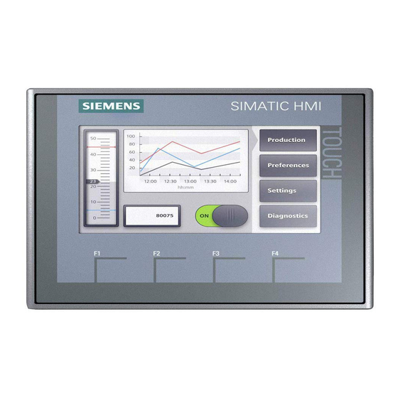
LOGO! TDE is described in LOGO! Set 9. For LOGO! Set 9 refer to the following entry: Building Automation Systems: House control with LOGO! and Master-Slave communication (LOGO! Set 9) https://support.industry.siemens.com/cs/ww/en/view/64143308 Monitoring with the KTP400 5.1.1 KTP400 screens All KTP screens have a uniform toolbar on the right: Press one of the buttons to go to the following screens: ... -
Page 28: Overview Of Weather Data
5 Operation 5.1.3 Overview of weather data Figure 5-2 This figure displays the current measured values from the weather sensors. House Control and Weather Sensors - LOGO! Set 11 Entry ID: 68585346, V2.1, 09/2018... -
Page 29: System Functions
5 Operation 5.1.4 System functions Figure 5-3 This screen provides system functions: Clean screen Calibrate (Data) transfer Runtime Stop More information on the system functions can be found in the Basic Panel manual \4\. House Control and Weather Sensors - LOGO! Set 11 Entry ID: 68585346, V2.1, 09/2018... -
Page 30: Online Support Information
5 Operation 5.1.5 Online Support information Figure 5-4 Information on the Online Support can be found here. The Home button (1) brings you back to the main menu. House Control and Weather Sensors - LOGO! Set 11 Entry ID: 68585346, V2.1, 09/2018... -
Page 31: Operator Control And Monitoring With Ktp700 And Ktp400
5 Operation Operator Control and Monitoring with KTP700 and KTP400 Table 5-1 Action/response KTP700 and KTP400 Verify on the KTP700 KTP700 (LOGO! Set 10) that "Automatic mode” for the blinds is activated. The wind speed KTP400 exceeds 20 km/h. KTP700 All blinds move up and stay in this final position for as long as the wind... - Page 32 5 Operation Action/response KTP700 and KTP400 KTP700 Press the "Alarm indicator” to open the "Alarm window” with the wind speed warning messages. KTP700 A warning message is displayed in the "Alarm window” that the wind has reached a moderate speed. Note: A total of 4 different warning messages have...
- Page 33 5 Operation Action/response KTP700 and KTP400 KTP700 Close the message window after you have cleared all warning messages. If the wind speed drops KTP400 below 18 km/h and at the same time there is high irradiation (>20 kLUX), all blinds will automatically close.
-
Page 34: Operation Via Pc
5 Operation Operation via PC Note When using the application example with your PC, please make sure the KTP400 or KTP700 is not connected with the other modules of the application example (LOGO! modules, PC, etc.). It is recommended not to connect the Basic Panel, if you already use your PC as a Basic Panel with the WinCC simulation. -
Page 35: Appendix
Industry Online Support Do you have any questions or need assistance? Siemens Industry Online Support offers round the clock access to our entire service and support know-how and portfolio. The Industry Online Support is the central address for information about our products, solutions and services. -
Page 36: Bibliographic References
Published by: Publicis ISBN: 9783895789267 LOGO!8 - MiniTrainerSchool Author: Klaus Machalek Product No.: LOGO! MTS Internet link specifications Table 6-2 Topic Link Siemens Industry Online Support http://support.industry.siemens.com Download page of the entry https://support.industry.siemens.com/cs/ww/en/view/68585 LOGO! 8 Manual https://support.industry.siemens.com/cs/ww/en/view/109741041 https://support.industry.siemens.com/cs/ww/en/view/90114350 HMI KTP400 Manual LOGO! http://w3.siemens.com/mcms/programmable-logic-...