Table of Contents
Quick Links
Basic Panels
SIMATIC HMI
HMI devices
Basic Panels
Operating Instructions
04/2012
A5E02421799-03
___________________
Preface
___________________
Overview
___________________
Safety instructions
___________________
Mounting and connecting
___________________
Operating the device
___________________
Configuring the HMI device
___________________
Commissioning a project
___________________
Maintenance and care
___________________
Technical specifications
___________________
Technical Support
___________________
Abbreviations
1
2
3
4
5
6
7
8
A
B
Table of Contents

Related Manuals for Siemens SIMATIC HMI KP300 Basic mono PN


Summary of Contents for Siemens SIMATIC HMI KP300 Basic mono PN
- Page 1 ___________________ Basic Panels Preface ___________________ Overview ___________________ Safety instructions SIMATIC HMI ___________________ Mounting and connecting HMI devices ___________________ Basic Panels Operating the device ___________________ Configuring the HMI device Operating Instructions ___________________ Commissioning a project ___________________ Maintenance and care ___________________ Technical specifications ___________________ Technical Support ___________________...
- Page 2 Note the following: WARNING Siemens products may only be used for the applications described in the catalog and in the relevant technical documentation. If products and components from other manufacturers are used, these must be recommended or approved by Siemens. Proper transport, storage, installation, assembly, commissioning, operation and maintenance are required to ensure that the products operate safely and without any problems.
-
Page 3: Preface
Preface Purpose of the operating instructions These operating instructions provide information based on the requirements defined by IEC 62079 for documentation. This information relates to the HMI device, its storage, transportation, place of use, installation, use and maintenance. These operating instructions are intended for a variety of target groups. The following table shows the chapters of these operating instructions that are of particular importance for the respective target group. - Page 4 Preface Scope These operating instructions are valid for all SIMATIC HMI Basic Panels. The following naming conventions apply: Device designation Device type Interface type Can be configured with SIMATIC HMI KP300 Basic mono PN Keyboard unit Basic Panel PN WinCC (TIA Portal) as of V11 KP400 Basic color PN WinCC (TIA Portal) as of V11 SP2 Update 2 with HSP Basic 4"...
- Page 5 Preface Illustrations and text highlighting This manual contains illustrations of the described devices. The illustrations may deviate from the supplied device in certain details. The following graphical highlighting facilitates reading these operating instructions: Graphical highlighting Description If the instructions involve several tasks, the individual tasks are highlighted by a red number circle.
- Page 6 Trademarks Names labeled with a ® symbol are registered trademarks of the Siemens AG. Other names used in this documentation may be trademarks, the use of which by third parties for their own purposes could violate the rights of the owner.
-
Page 7: Table Of Contents
Table of contents Preface ..............................3 Overview..............................11 Product Overview.........................11 Design of the KP300 Basic mono PN ..................12 Design of the KP400 Basic color PN ...................13 Design of the KTP400 Basic mono PN..................15 Design of the KTP400 Basic color PN ..................16 Design of the KTP600 Basic mono/color PN ................17 Design of the KTP600 Basic color DP ..................18 Design of the KTP1000 Basic color PN ..................19... - Page 8 Table of contents Switching on and testing the HMI device ..................48 Securing the cables........................50 Operating the device..........................51 Operating touch devices ......................51 4.1.1 Overview ............................. 51 4.1.2 General functions of the screen keyboard .................. 53 4.1.3 Entering data on the KTP400 Basic.................... 54 4.1.4 Entering data on the KTP600 Basic, KTP1000 Basic , TP1500 Basic ........
- Page 9 Table of contents Transfer............................91 6.4.1 Overview ............................91 6.4.2 Starting manual transfer.......................91 6.4.3 Starting automatic transfer......................93 6.4.4 Testing a project ..........................95 Backup and restore........................96 6.5.1 Overview ............................96 6.5.2 Backup and restore using WinCC flexible ...................97 6.5.3 Backup and restore using ProSave .....................99 6.5.4 Backup and restore using WinCC....................100 OS update - Basic Panel DP......................101...
- Page 10 Table of contents Specifications ..........................131 8.4.1 Power supply..........................131 8.4.2 KP300 Basic and KP400 Basic....................131 8.4.3 KTP400 Basic and KTP600 Basic .................... 133 8.4.4 KTP1000 Basic and TP1500 Basic................... 135 8.4.5 Ambient conditions........................137 8.4.5.1 Transport and storage conditions ..................... 137 8.4.5.2 Conditions of use ........................
-
Page 11: Overview
Overview Product Overview Concentrating on the essentials - the new Basic Panels Today, visualization is part of the standard repertoire for most machines. The cost factor plays a crucial role in this case, especially for small machines and simple applications. HMI devices with basic functions are often fully sufficient for simple applications. -
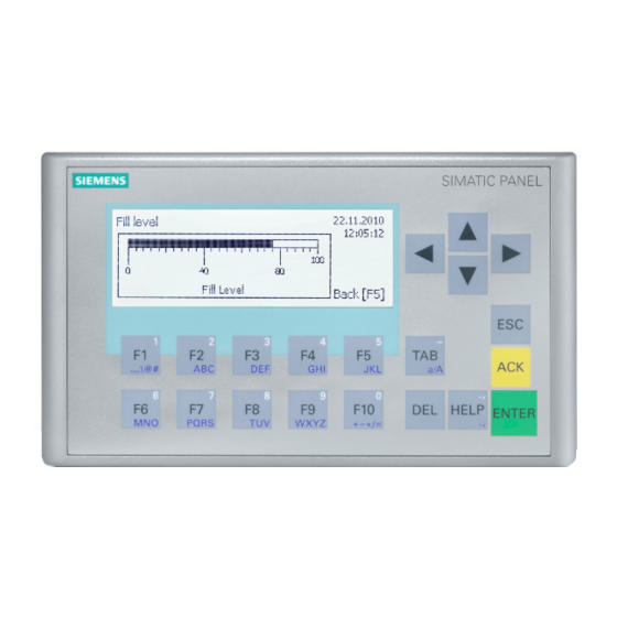
Page 12: Design Of The Kp300 Basic Mono Pn
Overview 1.2 Design of the KP300 Basic mono PN Design of the KP300 Basic mono PN ① ⑥ Power supply connector Function keys ② ⑦ PROFINET interface Rating plate ③ ⑧ Display Mounting seal ④ ⑨ Control keys Interface name ⑤... -
Page 13: Design Of The Kp400 Basic Color Pn
Overview 1.3 Design of the KP400 Basic color PN Design of the KP400 Basic color PN ① ⑤ Cutouts for mounting clamps Function keys ② ⑥ Power supply connector Control keys ③ ⑦ PROFINET interface Data input keys ④ Display Basic Panels Operating Instructions, 04/2012, A5E02421799-03... - Page 14 Overview 1.3 Design of the KP400 Basic color PN ① ④ Rating plate Functional earth connection ② ⑤ Mounting seal Guides for labeling strips ③ Interface name Basic Panels Operating Instructions, 04/2012, A5E02421799-03...
-
Page 15: Design Of The Ktp400 Basic Mono Pn
Overview 1.4 Design of the KTP400 Basic mono PN Design of the KTP400 Basic mono PN ① ⑥ Power supply connector Mounting seal ② ⑦ Functional earth connection Guide for a labeling strip ③ ⑧ PROFINET interface Function keys ④ ⑨... -
Page 16: Design Of The Ktp400 Basic Color Pn
Overview 1.5 Design of the KTP400 Basic color PN Design of the KTP400 Basic color PN ① ⑥ Cutouts for mounting clamps Guide for a labeling strip ② ⑦ Power supply connector Rating plate ③ ⑧ PROFINET interface Mounting seal ④... -
Page 17: Design Of The Ktp600 Basic Mono/Color Pn
Overview 1.6 Design of the KTP600 Basic mono/color PN Design of the KTP600 Basic mono/color PN ① ⑥ Power supply connector Function keys ② ⑦ PROFINET interface Rating plate ③ ⑧ Cutouts for a mounting clamp Interface name ④ ⑨ Display/touch screen Guide for a labeling strip ⑤... -
Page 18: Design Of The Ktp600 Basic Color Dp
Overview 1.7 Design of the KTP600 Basic color DP Design of the KTP600 Basic color DP ① ⑦ Power supply connector Rating plate ② ⑧ RS-422/RS-485 interface Interface name ③ ⑨ Cutouts for a mounting clamp DIP switch ④ ⑩ Display/touch screen Guide for a labeling strip ⑤... -
Page 19: Design Of The Ktp1000 Basic Color Pn
Overview 1.8 Design of the KTP1000 Basic color PN Design of the KTP1000 Basic color PN ① ⑦ Power supply connector Rating plate ② ⑧ PROFINET interface Interface name ③ ⑨ Cutouts for a mounting clamp Fixing element ④ ⑩ Display/touch screen Functional earth connection ⑤... -
Page 20: Design Of The Ktp1000 Basic Color Dp
Overview 1.9 Design of the KTP1000 Basic color DP Design of the KTP1000 Basic color DP ① ⑦ Power supply connector Rating plate ② ⑧ RS-422/RS-485 interface DIP switch ③ ⑨ Cutouts for a mounting clamp Interface name ④ ⑩ Display/touch screen Fixing element ⑤... -
Page 21: Design Of The Tp1500 Basic Color Pn
Overview 1.10 Design of the TP1500 Basic color PN 1.10 Design of the TP1500 Basic color PN ① ⑥ Power supply connector Rating plate ② ⑦ PROFINET interface Interface name ③ ⑧ Cutouts for a mounting clamp Fixing element ④ ⑨... -
Page 22: Product Package
Overview 1.11 Product package 1.11 Product package The following components are included in the product package of the HMI device. Name Figure Quantity HMI device Quick Installation Guide Mounting seal Included with KTP 600 Basic and already installed with all other HMI devices. -
Page 23: Accessories
Accessories Accessories are not included in the product package of the HMI device, but can ordered on the Internet under Industry Mall (http://mall.automation.siemens.com). This section contains the number of accessories available at the time of publication of the operating instructions. -
Page 24: Commissioning The Hmi Device
Overview 1.13 Commissioning the HMI device Protective foil Name Purpose Order no. Protective foil 4" Protective foil set for KTP400 Basic mono PN 6AV6 671-2EC00-0AX0 Protective foil 4" Protective foil set for KTP400 Basic color PN 6AV2124-6DJ00-0AX0 widescreen Protective foil 6" Protective foil set for KTP600 Basic 6AV6 671-2XC00-0AX0 Protective foil 10"... -
Page 25: Safety Instructions
Safety instructions General safety instructions Working on the control cabinet WARNING Open equipment The HMI device is open equipment. That means that the HMI device may only be installed in cubicles or cabinets that provide front panel access for operating the device. The cubicle or cabinet in which the HMI device is installed may only be accessed with a key or tool and only by trained, authorized personnel. -
Page 26: Security Information
2.2 Security information Security information Siemens offers IT security mechanisms for its portfolio of automation and drive products in order to support safe operation of the plant/machine. We recommend that you stay informed about the IT security developments for your products. For information on this topic, refer to: Industry Online Support (http://www.siemens.de/automation/csi_en_WW): You can register... - Page 27 Safety instructions 2.3 Notes about usage Notes on communication NOTICE Communication errors caused by address conflict Communication errors can occur if several devices in a network share the same bus address or IP address. Make sure that your HMI device is assigned a unique address in the network. Note Updating tag values following a communication error If communication between an HMI device and PLC is interrupted, all tag values displayed on...
- Page 28 Safety instructions 2.3 Notes about usage Basic Panels Operating Instructions, 04/2012, A5E02421799-03...
-
Page 29: Mounting And Connecting
Damaged parts Do not install parts damaged during shipment. In the case of damaged parts, contact your Siemens representative. The package content is described in section Product package (Page 22). Keep the supplied documentation in a safe place. The documentation belongs to the HMI device and is required for subsequent commissioning. - Page 30 Mounting and connecting 3.1 Preparations Horizontal mounting position All Basic HMI devices are suitable for horizontal mounting positions. The maximum ambient temperature at the device with vertical mounting in horizontal positions is 50 °C The following Basic HMI devices are also suitable for vertical mounting positions: KTP400 Basic...
-
Page 31: Checking Clearances
Mounting and connecting 3.1 Preparations 3.1.4 Checking clearances The following clearances are required around the HMI device to ensure sufficient self- ventilation: Required clearance around the HMI devices. All Basic KTP400 Basic All dimensions in mm Panels KTP600 Basic 3.1.5 Making the mounting cut-out NOTICE Stability of the mounting cutout... - Page 32 Mounting and connecting 3.1 Preparations Mounting compatibility The mounting cutouts of the Basic panels are compatible with the mounting cutouts of the following SIMATIC HMI devices: Mounting cutout for the Basic Compatible to the mounting cutouts of the HMI device Panel KP400 Basic OP77A, OP77B...
-
Page 33: Labeling The Function Keys
"CD_3\Documents\\Slides" directory on the WinCC/WinCC flexible DVD or on the Internet at: Downloads for Basic Panels (http://support.automation.siemens.c om/WW/view/en/28426379/133100) 2. Print the edited template on foil. 3. Apply a fixing spray film to the labeling strips. 4. Wait approx. 5 minutes until the fixing spray is dry and smear-proof. -
Page 34: Mounting The Hmi Device
Mounting and connecting 3.2 Mounting the HMI device Mounting the HMI device Required tools and accessories Slotted screwdriver, size 2 Mounting clamp type For HMI device Required quantity Aluminum mounting clamps KTP400 Basic mono KTP600 Basic KTP1000 Basic TP1500 Basic: Plastic mounting clamps KP300 Basic KP400 Basic... - Page 35 Mounting and connecting 3.2 Mounting the HMI device Securing the HMI device with aluminum mounting clamps 1. Insert the first clamp at the first position of the cutouts on the back of the HMI device. Set the clamp positions for your HMI device to match those of the figures in the following table row.
-
Page 36: Connecting The Hmi Device
Mounting and connecting 3.3 Connecting the HMI device Securing the HMI device with plastic mounting clamps 1. If mounting clamps and grub screws are available separately in the accessories bag, insert a grub screw into the mounting clamp bore hole and turn it several times. - Page 37 Mounting and connecting 3.3 Connecting the HMI device Torx screwdriver, size TX20 Crimp pliers Power supply terminal 24 VDC with sufficient amperage. See Specifications (Page 131) Procedure Keep to the following sequence of tasks when connecting the HMI device: 1. Connecting the equipotential bonding circuit (Page 38) 2.
-
Page 38: Connecting The Equipotential Bonding Circuit
Mounting and connecting 3.3 Connecting the HMI device 3.3.2 Connecting the equipotential bonding circuit Differences in electrical potential Differences in electrical potential can develop between spatially separated plant components. Such electrical potential differences can lead to high equalizing currents over the data cables and therefore to the destruction of their interfaces. -
Page 39: Connecting The Power Supply
Mounting and connecting 3.3 Connecting the HMI device Procedure 1. Interconnect functional ground of the HMI device with an grounding cable, cross-section 4 mm 2. Connect the grounding cable of the HMI device to the equipotential bonding rail. 3.3.3 Connecting the power supply Stripping the cable Use power supply cables with a maximum cross-section of 1.5 mm... - Page 40 Mounting and connecting 3.3 Connecting the HMI device Procedure CAUTION 24 VDC only An incorrectly dimensioned power supply can lead to destruction of the HMI device. Use a 24 VDC power supply with adequate amperage; see Specifications (Page 131). 1. Insert the two power cables into the mains terminal and secure them with a slotted screwdriver.
-
Page 41: Connecting A Programming Device
Mounting and connecting 3.3 Connecting the HMI device 3.3.4 Connecting a programming device A programming device provides the following options: ● Transferring projects. ● Transferring device images. Connecting a programming device to a Basic Panel DP Note A programming device cannot be used to reset the HMI device to factory settings. 1. -
Page 42: Connecting The Configuration Pc
Mounting and connecting 3.3 Connecting the HMI device 3.3.5 Connecting the configuration PC A configuring PC provides the following options: ● Transferring projects. ● Transferring device images. ● Resetting HMI device to factory settings. Connecting a configuring PC to a Basic Panel DP 1. - Page 43 Mounting and connecting 3.3 Connecting the HMI device Configuring the PC/PPI cable Configure the transmission speed using the DIP switches of the PC/PPI cable if using the PC/PPI cable to interconnect the HMI device with the configuring PC. Note Set a lower bit rate if the connection is lost during the operating system update. If you use a higher bit rate, you must use the PC/PPI cable release 3 or higher.
- Page 44 Mounting and connecting 3.3 Connecting the HMI device Connecting a configuring PC to a Basic Panel PN CAUTION Data network security for communication via Ethernet With Ethernet-based communication via PROFINET, the end user is himself responsible for the security of his data network; the proper functioning of the data network cannot be guaranteed in all circumstances, for example in the case of target attacks leading to an overloading of the device.
-
Page 45: Connecting The Plc
Mounting and connecting 3.3 Connecting the HMI device 3.3.6 Connecting the PLC If the HMI device contains an operating system and an executable project, connect the HMI device to the PLC. Note Note the following when connecting the PLC to a panel: •... - Page 46 Mounting and connecting 3.3 Connecting the HMI device Configuring an RS422/RS485 port A DIP switch for the configuration of the RS422/RS485 interface is located on the back of the HMI device. The DIP switch is set at the factory to enable communication with the SIMATIC PLC via RS 485.
- Page 47 Mounting and connecting 3.3 Connecting the HMI device Connecting the PLC to a Basic Panel PN CAUTION Data network security for communication via Ethernet With Ethernet-based communication via PROFINET, the end user is himself responsible for the security of his data network; the proper functioning of the data network cannot be guaranteed in all circumstances, for example in the case of target attacks leading to an overloading of the device.
-
Page 48: Switching On And Testing The Hmi Device
Mounting and connecting 3.4 Switching on and testing the HMI device Switching on and testing the HMI device Switching on the HMI device. Switching on the power supply. The screen lights up after power is switched on. A progress bar is displayed during startup. If the HMI device fails to start, you have probably crossed the wires on the power supply terminal. -
Page 49
Mounting and connecting 3.4 Switching on and testing the HMI device The Loader opens after the operating system has started. ● Touch devices: You operate the loader via the buttons on the touch screen ● Key devices: You use the cursor keys to operate the loader menu. You use the
... -
Page 50: Securing The Cables
Mounting and connecting 3.5 Securing the cables Securing the cables The following HMI devices come equipped with a fixing element on the back for strain relief: ● KTP1000 Basic DP ● KTP1000 Basic PN ● TP1500 Basic After the power-on test, use a cable tie to secure the connected cables to the marked fixing element in order to provide strain relief. -
Page 51: Operating The Device
Operating the device Operating touch devices 4.1.1 Overview Most Basic HMI devices feature a touch screen. Certain Basic HMI devices feature function keys. Use the touch screen and function keys to operate the Control Panel or the project running on your HMI device. DANGER Incorrect operation A project can contain certain operations that require in-depth knowledge about the specific... - Page 52 Operating the device 4.1 Operating touch devices They are basically operated in the same way as mechanical keys. You activate operating elements by touching them with your finger. Note The HMI device returns a visual feedback as soon as it detects that an operating element has been touched.
-
Page 53: General Functions Of The Screen Keyboard
Operating the device 4.1 Operating touch devices Operating function keys The function keys can be assigned global or local functions: ● Function keys with global function assignment A function key with global function assignment always triggers the same action on the HMI device or in the PLC, regardless of the currently displayed screen. -
Page 54: Entering Data On The Ktp400 Basic
Operating the device 4.1 Operating touch devices 4.1.3 Entering data on the KTP400 Basic Due to the small display, the screen keyboard and the input concept of the KTP400 Basic differs compared to other Basic HMI devices. The screen keyboard appears on the HMI device touch screen when you touch an operating element that requires input. - Page 55 Operating the device 4.1 Operating touch devices Note Job mailbox has no effect PLC job 51 "Select screen" has no effect while the screen keyboard is open. Key assignment The alphanumerical screen keyboard layout is monolingual. A language change within the project has no effect on the layout of the alphanumerical screen keyboard.
-
Page 56
Operating the device 4.1 Operating touch devices Entering numerical values 1. Touch the desired operating element on the screen. The numerical screen keyboard opens. 2. Enter the value. Depending on the settings, the HMI device outputs an audible signal. You can change the view of the screen keyboard for entering numbers with hexadecimal notation using the
... -
Page 57: Entering Data On The Ktp600 Basic, Ktp1000 Basic , Tp1500 Basic
Operating the device 4.1 Operating touch devices 4.1.4 Entering data on the KTP600 Basic, KTP1000 Basic , TP1500 Basic Alphanumerical screen keyboard The screen keyboard appears on the HMI device touch screen when you touch an operating element that requires input. Note Job mailbox has no effect PLC job 51 "Select screen"... -
Page 58
Operating the device 4.1 Operating touch devices Entering numerical values 1. Touch the desired operating element on the screen. The numerical screen keyboard opens. 2. Enter the value. Depending on the settings, the HMI device outputs an audible signal. 3. Press
key to confirm your entries, or cancel them with . -
Page 59: Operating Kp300 Basic
Operating the device 4.2 Operating KP300 Basic Operating KP300 Basic 4.2.1 Overview The KP300 Basic comes equipped with system keys. The system keys are as follows: ● Control keys ● Function keys with integrated alphanumeric keys Control keys The following table shows the function and effect of the control keys of the HMI device: Function Effect Moving the cursor... -
Page 60: Entering Data On The Kp300 Basic
Operating the device 4.2 Operating KP300 Basic Operating function keys The function keys can be assigned global or local functions: ● Function keys with global function assignment A function key with global function assignment always triggers the same action on the HMI device or in the PLC, regardless of the currently displayed screen. -
Page 61
Operating the device 4.2 Operating KP300 Basic The following figure shows the assignment using the "F5" function key as an example. ① Number assignment; automatically active when you enter numerical values ② Function key assignment; active by default If you change to editing mode in the Control Panel or project with
, the function assignment is disabled. -
Page 62
Operating the device 4.2 Operating KP300 Basic Operating a project Proceed as follows: 1. To navigate between operating elements: – Press
to navigate within a configured TAB order. – Use the cursor keys to navigate freely between operating elements. The operating element is selected. -
Page 63: Operating Kp400 Basic
Operating the device 4.3 Operating KP400 Basic Decimal places of numerical values The configuration engineer can define the number of decimal places for a numerical text box. The number of decimal places is checked when you enter a value in this type of I/O field. ●... - Page 64 Operating the device 4.3 Operating KP400 Basic The following table shows the functions that are available both in the Control Panel and in the project: Key or key Function combination Switches between upper and lower case Deletes the character left of cursor. Moves to the next operating element in the TAB order.
- Page 65 Operating the device 4.3 Operating KP400 Basic Operating the Control Panel and dialogs The following table shows additional key functions when operating the Control Panel and the associated dialogs. Key or key Function combination On tab level: Switches between tabs Within a text box: Positions the cursor Activates tab level, text boxes, buttons or options from top to bottom or from left to right...
-
Page 66: Entering Data On The Kp400 Basic
Operating the device 4.3 Operating KP400 Basic 4.3.2 Entering data on the KP400 Basic Data input on an HMI device is similar to operating the keys on a cell phone. Each key has several functions. When you press a data input key for long enough, the number is automatically inserted. -
Page 67: Configuring The Hmi Device
Configuring the HMI device Configuring devices with graphical Control Panel 5.1.1 Opening the Control Panel With the exception of the KP300 Basic mono PN, all Basic Panels have a graphic Control Panel. Open the Control Panel by pressing the "Control Panel" button of the Loader. -
Page 68: Overview
Configuring the HMI device 5.1 Configuring devices with graphical Control Panel Protecting the Control Panel with a password You can protect the Control Panel against unauthorized operation. You can read the settings in the Control Panel without having entered a password, however, you are not allowed to edit the settings. -
Page 69: Changing Mpi/Dp Settings
Configuring the HMI device 5.1 Configuring devices with graphical Control Panel 5.1.3 Changing MPI/DP settings Note The settings for MPI or PROFIBUS DP communication are defined in the HMI device project. Edit the transfer settings only in the following situations: •... -
Page 70: Changing The Network Configuration
Configuring the HMI device 5.1 Configuring devices with graphical Control Panel 5.1.4 Changing the network configuration NOTICE Communication errors caused by IP address conflicts Communication errors can occur if several devices in a network share the same IP address. Assign each HMI device an IP address that is unique within the network. 1. -
Page 71: Time Server Configuration
Configuring the HMI device 5.1 Configuring devices with graphical Control Panel 5.1.5 Time server configuration The HMI device has an unbuffered realtime clock. The realtime clock is set either using the configuration or using a time server. To fetch the time-of-day of the HMI device from a time server, specify up to four different time servers. -
Page 72: Changing Monitor Settings
Configuring the HMI device 5.1 Configuring devices with graphical Control Panel 5.1.6 Changing monitor settings NOTICE Orientation of the screen for KTP400 Basic and KTP600 Basic The screen orientation is defined by the configuration engineer in the course of project creation. -
Page 73: Displaying Information About The Hmi Device
Configuring the HMI device 5.1 Configuring devices with graphical Control Panel 5.1.7 Displaying information about the HMI device 1. Press "OP" to open the "OP Properties" dialog. 2. Open the "Device" tab. The "Device" tab is used to display specific information on the HMI device. -
Page 74: Calibrating The Touch Screen
Configuring the HMI device 5.1 Configuring devices with graphical Control Panel 5.1.8 Calibrating the touch screen This function is only available for touch screen devices. 1. Press "OP" to open the "OP Properties" dialog. 2. Change to the "Touch" tab. 3. -
Page 75: Displaying Licensing Information For The Hmi Device
Configuring the HMI device 5.1 Configuring devices with graphical Control Panel 5.1.9 Displaying licensing information for the HMI device 1. Press "OP" to open the "OP Properties" dialog. 2. Open the "License" tab. The "License" tab is used to display the licensing information for the software of the HMI device. -
Page 76: Enabling A Data Channel
Configuring the HMI device 5.1 Configuring devices with graphical Control Panel 5.1.10 Enabling a data channel You must enable at least one data channel to transfer a project to the HMI device. Note After having completed the project transfer, you can protect the HMI device against unintentional overwriting of project data and of the HMI device image by locking all data channels. - Page 77 Configuring the HMI device 5.1 Configuring devices with graphical Control Panel Enabling a data channel - Basic Panels PN 1. Press "Transfer" to open the "Transfer Settings" dialog. 2. Select the "Enable Channel" check box in the "Channel 1" field. Press the "Advanced"...
-
Page 78: Changing Password Settings
Configuring the HMI device 5.1 Configuring devices with graphical Control Panel 5.1.11 Changing password settings Password protection prevents unauthorized access to the Control Panel. NOTICE The password cannot contain spaces or special characters * ? . % / \ ' ". If the password is no longer available for the Control Panel, you first have to update the operating system before you can make any changes in the Control Panel. -
Page 79: Setting The Screen Saver
Configuring the HMI device 5.1 Configuring devices with graphical Control Panel 5.1.12 Setting the Screen Saver NOTICE Burn-in effect The screen contents may leave a faint version (ghost) of the image in the background if they appear for too long. The "ghost"... -
Page 80: Configuring Kp300 Basic
Configuring the HMI device 5.2 Configuring KP300 Basic Configuring KP300 Basic 5.2.1 Opening the Control Panel Use the "Info/Settings" menu command to open the Control Panel in the Loader. Configure your HMI device in the Control Panel. You can make the following settings: ●... -
Page 81: Overview
Configuring the HMI device 5.2 Configuring KP300 Basic 5.2.2 Overview The following table shows the menu structure of the Control Panel with the functions that are available there for configuring your HMI device. Menu entry Function / Note Start Transfer Info/Settings Contrast Changing monitor settings (Page 83) - Page 82 Configuring the HMI device 5.2 Configuring KP300 Basic Network Mode Changing the network configuration (Page 85) LLDP Protocol Enable Disable Auto Negotiation Enable Disable Speed Only available if "Auto Negotiation = Enable" 10 Mbits/s 100 Mbits/s Communication Link Only available if "Auto Negotiation = Enable" Half-Duplex Full-Duplex Time server configuration (Page 86)
-
Page 83: Displaying Information About The Hmi Device
Configuring the HMI device 5.2 Configuring KP300 Basic 5.2.3 Displaying information about the HMI device Menu commands in the "Info/Settings" menu The following table shows the menu commands in the "Info/Settings" menu: Menu item Information contained there Device Info HMI device name Size of the internal flash memory in which the HMI device image and project are stored The size of internal flash memory is not equivalent to application memory available for a project. -
Page 84: Enabling A Data Channel
Configuring the HMI device 5.2 Configuring KP300 Basic 5.2.5 Enabling a data channel You must enable at least one data channel to transfer a project to the HMI device. Note After having completed the project transfer, you can protect the HMI device against unintentional overwriting of project data and of the HMI device image by locking all data channels. -
Page 85: Changing The Network Configuration
Configuring the HMI device 5.2 Configuring KP300 Basic 5.2.6 Changing the network configuration NOTICE Communication errors caused by IP address conflicts Communication errors can occur if several devices in a network share the same IP address. Assign each HMI device an IP address that is unique within the network. Procedure Proceed as follows: 1. -
Page 86: Time Server Configuration
Configuring the HMI device 5.2 Configuring KP300 Basic 8. If you assign the connection type and transmission rate manually, select the desired values under "Speed" and "Communication Link". – Select "100 Mbps" or "10 Mbps". – Select "Half-Duplex" or "Full-Duplex". 5.2.7 Time server configuration Introduction... -
Page 87: Changing Password Settings
Configuring the HMI device 5.2 Configuring KP300 Basic 5.2.8 Changing password settings Password protection prevents unauthorized access to the "Info/Settings > Logon/Settings" menu. NOTICE The password cannot contain spaces or special characters * ? . % / \ ' ". If the password for the "Info/Settings >... -
Page 88: Setting The Screen Saver
Configuring the HMI device 5.2 Configuring KP300 Basic 5.2.9 Setting the Screen Saver NOTICE Burn-in effect The screen contents may leave a faint version (ghost) of the image in the background if they appear for too long. The "ghost" will disappear automatically after some time. The longer the same content is displayed on the screen, the longer it will take for the burn-in effect to disappear. -
Page 89: Commissioning A Project
Commissioning a project Overview Configuration phase A project – the process image of the working process – is created during configuration to visualize automated working processes. The process displays for the project contain displays for values and messages which provide information about process statuses. The process control phase follows the configuration phase. -
Page 90: Operating Modes
Commissioning a project 6.2 Operating modes Operating modes Operating modes The HMI device may be in the following operating modes: ● Offline ● Online ● Transfer "Offline mode" and "Online mode" can be set on both the configuring PC and the HMI device. -
Page 91: Data Transmission Options
Commissioning a project 6.3 Data transmission options Data transmission options Overview The following table shows the options for data transfer between the HMI device and configuration PC. Type Data channel Basic Panels DP Basic Panels PN Backup/restore, Serial Operating system update MPI/PROFIBUS DP Project transfers PROFINET... - Page 92 Commissioning a project 6.4 Transfer Procedure (WinCC flexible) Proceed as follows: 1. On the configuring PC, select the "Transfer settings" command from the "Project > Transfer" menu in WinCC flexible. The "Select devices for transfer" dialog opens. 2. Select the HMI device in the left area of the dialog. 3.
-
Page 93: Starting Automatic Transfer
Commissioning a project 6.4 Transfer 6.4.3 Starting automatic transfer Introduction If automatic transfer is activated, the HMI device automatically changes to "Transfer" mode at runtime as soon as a transfer is started on the connected configuring PC. Note With automatic transfer, the HMI device only changes into "Transfer" mode when the project is running on the HMI device. - Page 94 Commissioning a project 6.4 Transfer Procedure (WinCC flexible) Proceed as follows: 1. On the configuring PC, select the "Transfer settings" command from the "Project > Transfer" menu in WinCC flexible. The "Select devices for transfer" dialog opens. 2. Select the HMI device in the left area of the dialog. 3.
-
Page 95: Testing A Project
Commissioning a project 6.4 Transfer 6.4.4 Testing a project Introduction You have the following options to test a project: ● Test the project on the configuring PC You can test a project at a configuring PC, using a simulator. For detailed information, refer to the "WinCC flexible"... -
Page 96: Backup And Restore
Commissioning a project 6.5 Backup and restore Requirements for online testing ● The project has been transferred to the HMI device. ● The HMI device is in "Online" mode. Procedure In "Online" mode, you can test individual project functions on the HMI device without them being affected by the PLC. -
Page 97: Backup And Restore Using Wincc Flexible
Commissioning a project 6.5 Backup and restore See also Data transmission options (Page 91) 6.5.2 Backup and restore using WinCC flexible Requirement ● No project is open on the configuration PC in WinCC flexible. ● The HMI device is connected to this configuration PC. ●... - Page 98 Commissioning a project 6.5 Backup and restore Procedure – restoring Proceed as follows: 1. On the configuration PC, select the "Communication settings" command in the menu "Project > Transfer" in WinCC flexible. The "Communication settings" dialog box opens. 2. Select the type of HMI device. 3.
-
Page 99: Backup And Restore Using Prosave
Commissioning a project 6.5 Backup and restore 6.5.3 Backup and restore using ProSave Requirements ● The HMI device is connected to a PC on which ProSave is installed. ● The data channel is parameterized on the HMI device. Procedure – backup Proceed as follows: 1. -
Page 100: Backup And Restore Using Wincc
Commissioning a project 6.5 Backup and restore Procedure – restore Proceed as follows: 1. Go to the Windows Start menu and start ProSave on the PC. 2. Select the HMI device type in the "General" tab. 3. Select the type of interconnection for the HMI device and the PC. 4. -
Page 101: Os Update - Basic Panel Dp
Commissioning a project 6.6 OS update - Basic Panel DP Restoring the data of the HMI device Proceed as follows: 1. Select the "Restore" command from the "Online > HMI device maintenance" menu. 2. Enter the name of the backup file under "Save as". Information about the selected backup file is displayed under "Content". -
Page 102: Resetting Factory Settings
Commissioning a project 6.6 OS update - Basic Panel DP 6.6.2 Resetting factory settings In ProSave, WinCC flexible or WinCC, you can update the operating system with or without resetting to factory settings. ● Updating the operating system without reset to factory settings First, switch into "Transfer"... - Page 103 Commissioning a project 6.6 OS update - Basic Panel DP Requirements ● The HMI device is connected to a configuring PC. ● No project is open in WinCC flexible. ● When updating the operating system without reset to factory setting only: The data channel is configured on the HMI device.
-
Page 104: Updating The Operating System Using Prosave
Commissioning a project 6.6 OS update - Basic Panel DP 6.6.4 Updating the Operating System using ProSave Requirements ● The HMI device is connected to a PC on which ProSave is installed. ● When updating the operating system without reset to factory settings only: The data channel is configured on the HMI device. -
Page 105: Os Update - Basic Panel Pn
Commissioning a project 6.7 OS update - Basic Panel PN OS update - Basic Panel PN 6.7.1 Overview Updating the operating system A compatibility conflict may occur when transferring a project to the HMI device. This is caused by different versions of the configuration software used and the HMI device image available on the HMI device. -
Page 106: Resetting Factory Settings
Commissioning a project 6.7 OS update - Basic Panel PN 6.7.2 Resetting factory settings In ProSave, WinCC flexible or WinCC, you can update the operating system with or without resetting to factory settings. ● Updating the operating system without reset to factory settings First, switch into "Transfer"... - Page 107 Commissioning a project 6.7 OS update - Basic Panel PN Requirements ● No project is open on the configuring PC in WinCC flexible. ● The HMI device is connected to this configuring PC. ● The data channel is configured on the HMI device. Procedure Proceed as follows: 1.
-
Page 108: Updating The Operating System Using Prosave
Commissioning a project 6.7 OS update - Basic Panel PN 6.7.4 Updating the operating system using ProSave Requirements ● The HMI device is connected to a PC on which ProSave is installed. ● The data channel is configured on the HMI device. Procedure Proceed as follows: 1. -
Page 109: Updating The Operating System Using Wincc
Commissioning a project 6.7 OS update - Basic Panel PN 6.7.5 Updating the operating system using WinCC If possible, you should use the interface with the highest bandwidth for this connection, such as Ethernet. Updating the operating system via a serial connection can take up to an hour. CAUTION Updating the operating system deletes all data on the HMI device When you update the operating system you delete data on the target system. -
Page 110: Resetting To Factory Settings With Wincc Flexible
Commissioning a project 6.7 OS update - Basic Panel PN 6.7.6 Resetting to factory settings with WinCC flexible CAUTION Updating the operating system deletes all data on the HMI device When you update the operating system you delete data on the target system. For this reason, it is advisable to backup the following data: •... - Page 111 Commissioning a project 6.7 OS update - Basic Panel PN Note Possible address conflicts with incorrect IP address Do not use a dynamic IP configuration for "Reset to factory settings". Specify a unique IP address in which the configuring PC is located. For the duration of the update process, the HMI device is automatically assigned to the specified address.
-
Page 112: Resetting To Factory Settings With Prosave
Commissioning a project 6.7 OS update - Basic Panel PN 6.7.7 Resetting to factory settings with ProSave Requirement ● The HMI device is connected over the Ethernet to a PC on which ProSave is installed. ● Have the MAC address of your HMI device's Ethernet interface to hand. –... - Page 113 Commissioning a project 6.7 OS update - Basic Panel PN 4. Change to the "OS Update" tab. 5. Select the "Reset to factory settings" check box. A text box opens where you can enter the MAC address. 6. Enter the HMI device's MAC address in the text box. 7.
-
Page 114: Resetting To Factory Settings With Wincc
Commissioning a project 6.7 OS update - Basic Panel PN 6.7.8 Resetting to factory settings with WinCC If possible, you should use the interface with the highest bandwidth for this connection, such as Ethernet. Updating the operating system via a serial connection can take up to an hour. CAUTION Updating the operating system deletes all data on the HMI device When you update the operating system you delete data on the target system. -
Page 115: Maintenance And Care
Maintenance and care Maintenance and care Introduction The HMI device is designed for maintenance-free operation. Make sure you keep the touch screen and keyboard membrane clean. Requirements Use a cleaning cloth dampened with a cleaning agent to clean the equipment. Only use water with a little liquid soap or a screen cleaning foam. -
Page 116: Recycling
Maintenance and care 7.2 Recycling Recycling Recycling and disposal The HMI devices described in these operating instructions can be recycled due to the low levels of pollutants. Contact a certified disposal service company for environmentally sound recycling and disposal of your old devices. Basic Panels Operating Instructions, 04/2012, A5E02421799-03... -
Page 117: Technical Specifications
● 2004/108/EC "Electromagnetic Compatibility" (EMC Directive) EC Declaration of Conformity The EC Declarations of Conformity are available to the relevant authorities at the following address: Siemens AG Industry Sector I IA AS FA WF AMB PO Box 1963 D-92209 Amberg, Germany Marking for Australia The HMI device fulfills the requirements of standard AS/NZS 2064 (Class A). -
Page 118: Directives And Declarations
Technical specifications 8.2 Directives and declarations Directives and declarations 8.2.1 Electromagnetic compatibility Introduction The HMI device fulfills, among other things, the requirements of the EMC law pertaining to the domestic European market. EMC-compatible installation of the HMI device The EMC-compliant installation of the HMI device and the application of interference-proof cable is the basis for interference-free operation. -
Page 119: Esd Guideline
Technical specifications 8.2 Directives and declarations Sinusoidal interference The following table shows the EMC behavior of the modules with respect to sinusoidal interference. This requires the HMI device to meet the specifications and directives for electrical installation. Sinusoidal interference Test values Degree of severity HF radiation (in... - Page 120 Technical specifications 8.2 Directives and declarations Electrostatic sensitive devices can be labeled with an appropriate symbol. CAUTION Damage to ESD from touch Electrostatic sensitive devices, ESD, can be destroyed by voltages which are far below the human perception limit. If you touch a component or electrical connections of a module without discharging any electrostatic energy, these voltages may arise.
- Page 121 Technical specifications 8.2 Directives and declarations CAUTION Grounding measures There is no equipotential bonding without grounding. An electrostatic charge is not discharged and may damage the ESD. Protect yourself against discharge of static electricity. When working with electrostatic sensitive devices, make sure that the person and the workplace are properly grounded. Protective measures against discharge of static electricity ●...
-
Page 122: Dimension Drawings
Technical specifications 8.3 Dimension drawings Dimension drawings 8.3.1 Dimension drawing of the KP300 Basic mono PN Basic Panels Operating Instructions, 04/2012, A5E02421799-03... -
Page 123: Dimension Drawing Of The Kp400 Basic Color Pn
Technical specifications 8.3 Dimension drawings 8.3.2 Dimension drawing of the KP400 Basic color PN Basic Panels Operating Instructions, 04/2012, A5E02421799-03... -
Page 124: Dimension Drawing Of The Ktp400 Basic Mono Pn
Technical specifications 8.3 Dimension drawings 8.3.3 Dimension drawing of the KTP400 Basic mono PN Basic Panels Operating Instructions, 04/2012, A5E02421799-03... -
Page 125: Dimension Drawing Of The Ktp400 Basic Color Pn
Technical specifications 8.3 Dimension drawings 8.3.4 Dimension drawing of the KTP400 Basic color PN Basic Panels Operating Instructions, 04/2012, A5E02421799-03... -
Page 126: Dimension Drawing Of The Ktp600 Basic Color Dp
Technical specifications 8.3 Dimension drawings 8.3.5 Dimension drawing of the KTP600 Basic color DP Basic Panels Operating Instructions, 04/2012, A5E02421799-03... -
Page 127: Dimension Drawing Of The Ktp600 Basic Mono/Color Pn
Technical specifications 8.3 Dimension drawings 8.3.6 Dimension drawing of the KTP600 Basic mono/color PN Basic Panels Operating Instructions, 04/2012, A5E02421799-03... -
Page 128: Dimension Drawing Of The Ktp1000 Basic Color Dp
Technical specifications 8.3 Dimension drawings 8.3.7 Dimension drawing of the KTP1000 Basic color DP Basic Panels Operating Instructions, 04/2012, A5E02421799-03... -
Page 129: Dimension Drawing Of The Ktp1000 Basic Color Pn
Technical specifications 8.3 Dimension drawings 8.3.8 Dimension drawing of the KTP1000 Basic color PN Basic Panels Operating Instructions, 04/2012, A5E02421799-03... -
Page 130: Dimension Drawing Of The Tp1500 Basic Color Pn
Technical specifications 8.3 Dimension drawings 8.3.9 Dimension drawing of the TP1500 Basic color PN Basic Panels Operating Instructions, 04/2012, A5E02421799-03... -
Page 131: Specifications
Technical specifications 8.4 Specifications Specifications 8.4.1 Power supply CAUTION Safe electrical isolation Use only 24 VDC power supply units with safe electrical isolation in accordance with IEC 60364-4-41 or HD 384.04.41 (VDE 0100, Part 410), e.g. to PELV standard. The supply voltage must be within the specified voltage range. Otherwise, malfunction at the HMI device cannot be ruled out. - Page 132 Technical specifications 8.4 Specifications KP300 Basic mono PN KP400 Basic color PN Backlighting Half Brightness Life Time (MTBF 50,000 h Pixel error class according to DIN EN ISO 13406-2 MTBF: Operating hours after which the maximum brightness is reduced by half compared to the original value. MTBF is increased by using the integrated dimming function, for example, time-controlled via screen saver or centrally via PROFIenergy.
-
Page 133: Ktp400 Basic And Ktp600 Basic
Technical specifications 8.4 Specifications 8.4.3 KTP400 Basic and KTP600 Basic Weight KTP400 Basic KTP400 Basic KTP600 Basic KTP600 Basic KTP600 Basic mono PN color PN mono PN color DP color PN Weight without packaging Approx. 320 g Approx. 340 g Approx. - Page 134 Technical specifications 8.4 Specifications Interfaces KTP400 Basic KTP400 Basic KTP600 Basic KTP600 Basic KTP600 Basic mono PN color PN mono PN color DP color PN 1 x RS 422/RS 485 Max. 12 Mbps 1 x Ethernet RJ45 10/100 Mbps 10/100 Mbps Supply voltage KTP400 Basic KTP400 Basic...
-
Page 135: Ktp1000 Basic And Tp1500 Basic
Technical specifications 8.4 Specifications 8.4.4 KTP1000 Basic and TP1500 Basic HMI device KTP1000 Basic color DP KTP1000 Basic color PN TP1500 Basic color PN Weight without packaging Approx. 2.65 kg Approx. 4.2 kg Display KTP1000 Basic color DP KTP1000 Basic color PN TP1500 Basic color PN Type LCD TFT... - Page 136 Technical specifications 8.4 Specifications Supply voltage KTP1000 Basic color DP KTP1000 Basic color PN TP1500 Basic color PN Rated voltage +24 V DC Range, permissible 19.2 to 28.8 V (–20%, +20%) Transients, maximum permissible 35 V (500 ms) Time between two transients, 50 s minimum Current consumption...
-
Page 137: Ambient Conditions
Technical specifications 8.4 Specifications 8.4.5 Ambient conditions 8.4.5.1 Transport and storage conditions Mechanical and climatic conditions for transportation and storage The transport and storage conditions of this HMI device exceed requirements in accordance with IEC 61131-2. The following specifications apply to the transport and storage of an HMI device in its original packaging. -
Page 138: Conditions Of Use
Technical specifications 8.4 Specifications 8.4.5.2 Conditions of use Mechanical and climatic conditions of use The HMI device is designed for use in a location protected from the effects of the weather. The conditions of use are compliant with requirements to DIN IEC 60721-3-3: ●... - Page 139 Technical specifications 8.4 Specifications Testing mechanical ambient conditions The following table provides information on the type and scope of tests for mechanical ambient conditions. Tested for Test standard Comments Vibrations Vibration test in accordance Type of vibration: with IEC 60068, part 2–6 Transitional rate of the frequency: (sinusoidal) 1 octave/minute.
-
Page 140: Information On Insulation Tests, Protection Class And Degree Of Protection
Technical specifications 8.4 Specifications 8.4.5.3 Information on insulation tests, protection class and degree of protection Test voltages Insulation strength is demonstrated in the type test with the following test voltages in accordance with IEC 61131-2: Circuits with a nominal voltage of U to other Test voltage circuits or ground... -
Page 141: Interface Description
Technical specifications 8.5 Interface description Interface description 8.5.1 Power supply Plug connector, 2-pin Pin number Assignment +24 VDC (L+) GND 24 V (M) 8.5.2 PROFIBUS (Sub-D RS422/485) Name of interface on HMI device: X2 Sub-D socket, 9-pin, with screw lock Assignment for the RS 422 Assignment for the RS 485 n. -
Page 142: Profinet (Ethernet)
Technical specifications 8.5 Interface description 8.5.3 PROFINET (Ethernet) Name of interface on HMI device: X1 RJ45 plug connector Assignment Tx– n. c. n. c. Rx– n. c. n. c. Meaning of LEDs State Green "SPEED" LED Yellow "LINK" LED No connection 10 MB connection 100 MB connection Active data transfer 10 MB... -
Page 143: Functional Scope With Wincc Flexible And Wincc
Technical specifications 8.6 Functional scope with WinCC flexible and WinCC Functional scope with WinCC flexible and WinCC The following tables show the objects that can be integrated in a project for a Basic Panel. Alarms Object Specification Basic Panels Alarms Number of discrete alarms Number of analog alarms Length of the alarm text... - Page 144 Technical specifications 8.6 Functional scope with WinCC flexible and WinCC Recipes The specified values are maximum values and should not be used additive. Object Specification Basic Panels Recipes Quantity Elements per recipe Data records per recipe Safety Object Specification Basic Panels Safety Number of user groups Number of users...
- Page 145 Technical specifications 8.6 Functional scope with WinCC flexible and WinCC New system functions In addition to the system functions already available, WinCC flexible 2008 SP2 and WinCC V11 or higher support the following system functions for the Basic Panels: System function/syntax Application SetBitInTag (Tag, Bit) Sets a bit in the specified tag to 1 (TRUE).
- Page 146 Technical specifications 8.6 Functional scope with WinCC flexible and WinCC Basic Panels Operating Instructions, 04/2012, A5E02421799-03...
-
Page 147: Technical Support
Service and support You can find additional information and support for the products described on the Internet at the following addresses: ● Technical support (http://www.siemens.de/automation/csi_en_WW) ● Support request form (http://www.siemens.com/automation/support-request) ● After-sales information system for SIMATIC PC / PG (http://www.siemens.com/asis) ●... -
Page 148: System Events
Technical Support A.2 System events System events System events on the HMI device provide information about internal states of the HMI device and PLC. Note System events are only indicated if an alarm window was configured. System events are output in the language currently set on your HMI device. System event parameters System events may contain encrypted parameters which are relevant to troubleshooting because they provide a reference to the source code of the runtime software. -
Page 149: Abbreviations
Abbreviations ANSI American National Standards Institution Central Processing Unit Comma Separated Values Clear To Send Direct Current Data Carrier Detect DHCP Dynamic Host Configuration Protocol Dual-in-Line (electronic chip housing design) Domain Name System Distributed I/O Data Source Name Data Set Ready Data Terminal Ready Input and Output Components and modules endangered by electrostatic discharge... - Page 150 Abbreviations PELV Protective Extra Low Voltage RJ45 Registered Jack Type 45 Request to send Receive Data SD Card Security Digital Card SELV Safety Extra Low Voltage Service Pack Programmable Logic Controller Super Twisted Nematic Sub-D Subminiature D (plug) Tabulator TCP/IP Transmission Control Protocol/Internet Protocol Thin Film Transistor Teletype...
-
Page 151: Glossary
Glossary "Transfer" mode HMI device operating mode for transferring an executable project from the configuring PC to an HMI device. Acknowledge Acknowledgment of an alarm confirms that it has been noted. Alarm, acknowledgment Acknowledgment of an alarm confirms that it has been noted. Alarm, activated Moment at which an alarm is triggered by the PLC or HMI device. - Page 152 Glossary Configuring PC A configuring PC is a programming device or PC on which plant projects are created using an engineering software. Display duration Defines whether a system alarm is displayed on the HMI device and the duration of the display.
- Page 153 Glossary HMI device image The HMI device image is a file that can be transferred from the configuring PC to the HMI device. The HMI device image contains the operating system of the HMI device , including the elements of the Runtime software required for the executable project file. I/O field Enables the input or output of values on the HMI device and their transfer to the PLC.
- Page 154 Glossary Project A project is the result of a configuration using an engineering software. The project usually contains several screens with embedded system-specific objects, basic settings and alarms. A project configured in WinCC flexible is saved to a project file with the extension *.hmi. There is a difference between an offline project on a configuring PC and an online executable project on an HMI device.
- Page 155 Glossary Runtime software The Runtime software is a process visualization software which can be used to test projects on a configuring PC. Screen Mode of visualization of all logically associated process data of a plant. Visualization of the process data can be supported by means of graphic objects. Screen object Refers to objects such as rectangles, I/O fields, or alarm views which are configured for visualization or operation of the plant.
- Page 156 Glossary Transfer Transfer of an executable project from the configuring PC to the HMI device. WinCC WinCC (TIA Portal) is engineering software for configuring SIMATIC Panels, SIMATIC Industrial PC and standard PC with the visualization software WinCC Runtime Advanced or the SCADA system, WinCC Runtime Professional.
-
Page 157: Index
Index Clock KP300 Basic, 132 KTP1000 Basic, TP1500 Basic, 136 KTP400 Basic, KTP600 Basic, 134 Commissioning engineers, 3 ACK key, 65 Compatibility conflict, 96 Acknowledge key, 65 Components sensitive to electrostatic charge, 119 Activating Conductor cross-section Automatic transfer, 84 Equipotential bonding, 38 Ambient conditions Configuration phase, 89 Climatic, 139... - Page 158 Index Display Functional scope KP300 Basic, 131 Alarm buffer, 143 KTP1000 Basic, TP1500 Basic, 135 Alarms, 143 KTP400 Basic, KTP600 Basic, 133 Graphic objects, 144 Disposal, 116 Infotext, 144 Disturbance Language change, 144 Pulse-shaped, 118 Limit value monitoring, 143 Sinusoidal, 119 Recipes, 144 Safety, 144 Scaling, 143...
- Page 159 Index Interfaces Mounting clamp KP300 Basic, 132 Aluminum, 35 KTP1000 Basic, TP1500 Basic, 135 Plastic, 36 KTP400 Basic, KTP600 Basic, 134 MPI/Profibus Settings, 68 IT Security, 26 Non-isolated plant configuration, 131 ACK, 65 Cancel, 64 Cursor, 64 Offline Delete, 64 Operating mode, 90 END, 64 Test, 95...
- Page 160 Index Package content Safe electrical isolation, 131 Checking, 29 Safety Password properties, 68 Standards, 117 Password protection, 68, 80 Safety instruction Activating, 78, 87 Compatibility conflict, 96 Deactivating, 78, 87 Data channel, 102, 106 PELV, 131 Data loss, 101, 105 Plant configuration Equipotential bonding cable, 38 Non-isolated, 131...
- Page 161 Index Storage conditions, 137 Strain relief, 50 UL approval, 117 Stripping, 39 Update Supply voltage Using WinCC flexible, 103 KP300 Basic, 132 Updating KTP1000 Basic, TP1500 Basic, 136 Operating system, 101, 105 KTP400 Basic, KTP600 Basic, 134 Operating system of the HMI device, 109 Switching on Using ProSave, 104, 108 HMI device, 48...
- Page 162 Index Basic Panels Operating Instructions, 04/2012, A5E02421799-03...