Table of Contents
Quick Links
Table of Contents
Troubleshooting

Related Manuals for Honeywell FlexLine SmartServo 954


Summary of Contents for Honeywell FlexLine SmartServo 954
- Page 1 Service Manual 954 SmartServo FlexLine...
- Page 2 GENERAL For service related questions contact: Head Office - Delft, The Netherlands Honeywell Enraf Delftechpark 39, 2628 XJ Delft PO Box 812, 2600 AV Delft The Netherlands Tel.: +31 (0)15 2701 100 Fax: +31 (0)15 2701 111 E-mail: [email protected] Website: www.honeywellprocess.com...
- Page 3 GENERAL About this manual This manual is a detailed how to reference for servicing the 954 SmartServo FlexLine. For installing, wiring, configuring, starting up, operating, maintaining and calibrating refer to the 954 SmartServo FlexLine Installation guide listed below in References. For Safety instructions and procedures refer to the 954 SmartServo FlexLine Safety manual listed below in References.
- Page 4 GENERAL Patents The Honeywell 954 SmartServo FlexLine servo-based level gauge is covered by the following patents: US2017307461 (A1) 2017-10-26, US2018058960 (A1) 2018-03-01 WO2017062413 (A1) 2017-04-13, WO2018044518 (A1) 2018-03-18 Service Manual Part No.: 4417340 Revision 1 954 SmartServo FlexLine...
- Page 5 GENERAL Table of Contents GENERAL ............................. 1 Target Group for this Service Manual ....................1 Structure of this Manual ........................1 Trademarks ............................1 SAFETY AND SECURITY ......................... 2 General ..............................2 Safety Conventions ..........................2 WARNINGS ............................2 Cautions ............................2 Safety Instructions ..........................
- Page 6 GENERAL Entities ..............................22 Status Entities ..........................22 Generic Entity ..........................24 Function-specific Entities ........................ 24 HART SmartView Display ........................25 General ............................25 Status Entities on HART SmartView ....................26 Generic Entities on HART SmartView ....................27 Specific Entities on HART SmartView ....................27 Engauge Service Tool ...........................
- Page 7 GENERAL Average Temperature Measurement (FII-RTD) ................136 HART Analog Outputs (HCI-HAO) ....................148 TRL/2 Fieldbus (HCI-TRL) ....................... 159 Integrated display (TII-LCD) ......................188 SIL overfill and underfill protection (FII-SIL) ................. 213 Errors ............................214 Commissioning ..........................219 Proof Testing ..........................219 Entities ............................
- Page 8 GENERAL Drum compartment ........................... 263 Removing the measuring drum ....................265 Replacing the drum bearings ......................266 The electronic compartment ......................267 Detailed description ........................267 Dismantling the electronic compartment ..................268 Calibrating force transducer ......................271 Synchronizing the reference encoder ....................275 954 Density option ..........................
- Page 9 GENERAL GENERAL Target Group for this Service Manual The 954 SmartServo FlexLine Service Manual is intended for service engineers who are assigned to commission the 954 SmartServo FlexLine. Structure of this Manual Chapter Title Description 1 - GENERAL This chapter provides the introductory information for the manual.
- Page 10 SAFETY AND SECURITY SAFETY AND SECURITY General The 954 SmartServo FlexLine is a servo-based level gauge which is used in inventory measurement systems. It can also be used to interface with other systems and sensors such as pressure, density, or temperature sensors.
- Page 11 The entire electrical installation shall be carried out in accordance with the national requirements for electrical equipment to be installed in hazardous areas. Additional Information If you require additional information, contact Honeywell or its representative. Environmental Conditions Observe the environmental conditions for the temperature and the pressure.
- Page 12 WARNING! Only certified technicians are authorized to make changes on the 954 SmartServo FlexLine configuration. All modifications must be in accordance to the guidelines as set forth by Honeywell. Modifications not authorized by Honeywell will invalidate the approval certificates. Labels NOTE: This is a conceptual view of the type plate and therefore subject to change.
- Page 13 SAFETY AND SECURITY Personal Safety WARNING! National, local and company regulations regarding personal safety must be followed. Pay attention to the kind of product in the tank. If there is any danger for your health, wear a gas mask and take all the necessary precautions.
- Page 14 SAFETY AND SECURITY 2.7.1.3 Working Environment 2.7.1.3.1 Hazardous Area WARNING! Potential Electrostatic Charging Hazard! Avoid generation of static electricity. 2.7.1.3.2 Safe Area WARNING! Avoid generation of static electricity. Make sure no explosive gas mixtures are build up in the working area. 2.7.1.4 Required Skills WARNING! The technician must be trained and qualified to safely install...
- Page 15 SAFETY AND SECURITY Accordance to Regulations Explosion Safety • ATEX SmartServo FlexLine II 1/2 G Ex d IIB T6 or Ex d [ia] IIB T6 according to KEMA 07ATEX0010 X • IECEx SmartServo FlexLine without Integrated (HART) HART SmartView Zone 0/1 Ex d IIB T6 or Ex d [ia] IIB T6 according to IECEx KEM 07.0003X •...
- Page 16 SAFETY AND SECURITY 2.9.1.1 IC (Industry Canada) Industry Canada Statement: This device complies with RSS-210 of the Industry Canada Rules. Operation is subject to the following two conditions: 1. This device may not cause interference and 2. This device must accept any interference, including interference that may cause undesired operation of the device.
- Page 17 SAFETY AND SECURITY 2.10 Security Considerations The 954 SmartServo FlexLine provides several features designed to prevent accidental changes to the device configuration or calibration data. These features include: • Configuration Lock protection of HART SmartView local commissioning tool and display •...
- Page 18 SAFETY AND SECURITY Security note 1 During commissioning the hardware full configuration write protect jumper / switch for each FlexConn board should be placed so no unintended or accidental configuration changes will be possible. For security and unintended changes by people that are not allowed making changes the "Protect all configuration jumper"...
- Page 19 To report potential security vulnerability against any Honeywell product, please follow the instructions at: https://honeywell.com/pages/vulnerabilityreporting.aspx Submit the requested information to Honeywell using one of the following methods: Send an email to [email protected]. Contact your local Honeywell Process Solutions Customer Contact Centre (CCC) or Honeywell Technical Assistance Centre (TAC) listed in the “Support and Contact information”...
- Page 20 PRINCIPAL OF SERVO MEASUREMENT PRINCIPAL OF SERVO MEASUREMENT Principle of measurement Figure 3-1 Principle of measurement The principle is based on detection of variations in the buoyancy of a displacer. The displacer is suspended from a strong, flexible measuring wire which is stored on a precisely grooved measuring drum. The shaft of the drum is connected to the stepper motor via a magnetic coupling.
- Page 21 PRINCIPAL OF SERVO MEASUREMENT Level measurement A level variation of product, in which the displacer is partially immersed, causes a change in buoyancy, which will be detected by the force transducer. The resulting difference between measured and desired value will cause a variation in the position of the stepper motor and consequently raise or lower the position of the displacer until the measured value equals the desired value.
- Page 22 PRINCIPAL OF SERVO MEASUREMENT Servo gauges Servo tank gauges (Figure 3-2) are a considerable improvement over the float driven instruments. They were developed during the1950s. In this gauge, the float is replaced by a small displacer, suspended by a strong, flexible measuring wire. Instead of a spring-motor, servo gauges use an electrical servo motor to raise and lower the displacer.
- Page 23 PRINCIPAL OF SERVO MEASUREMENT The original servo gauge does not look much like today's modern version. The instruments have evolved into highly reliable mature products, and are gradually replacing mechanical float gauges, cutting down on maintenance and improving on inventory results. Modern intelligent servo gauge shave very few moving parts, resulting in long term reliability and accuracy.
- Page 24 SYSTEM ARCHITECTURE SYSTEM ARCHITECTURE 954 SmartServo FlexLine Architecture The 954 SmartServo FlexLine system is built up from interchangeable hardware modules. These modules consist of uniform printed circuit boards (PCBs), each of them representing a different, unique functionality. Together with the software implemented on these hardware parts, each PCB makes up a FlexConn module.
- Page 25 SYSTEM ARCHITECTURE FlexConn Modules One of the main characteristics of the 954 SmartServo FlexLine architecture is its placement flexibility of the FlexConn modules. Any types of modules can be added. Two identical modules can also be placed in the 954 SmartServo FlexLine system. Each FlexConn module has one or more function.
- Page 26 SYSTEM ARCHITECTURE Each FlexConn PCB consists of a generic and a specific electronic part. The generic part can be found on any FlexConn modules. The specific electronics part represents an application-specific function. Figure 4-3. Figure 4-3 A typical FlexConn PCB layout The following parts are available on the generic electronics part.
- Page 27 SYSTEM ARCHITECTURE The commissioning parameters and the diagnostics data are stored when the power is switched off. Jumpers: With the jumpers, specific hardware settings can be made: Jumper Function Number All warning and monitoring-related commissioning entities protected and cannot be changed The password is protected from being read All commissioning entities are protected and cannot be changed Board-specific jumper...
- Page 28 SYSTEM ARCHITECTURE Entities. Health LED The Health LED (= LE1, the blue circle) indicates the general health status of the FlexConn module. Health Status Flashing Pattern Good Uncertain 2 function LEDs These LEDS indicate module-specific activities, such as for instance data being transmitted or received.
- Page 29 SYSTEM ARCHITECTURE 3 voltage monitors The output of these monitors, being voltage levels from three different FlexConn PCB locations, are used for diagnostics purposes. Figure 4-4 Figure 4-4 Locations of the 3 voltage monitors 1 temperature sensor For the operational PCB, this sensor acts as an input for environmental- temperature diagnostics.
- Page 30 SYSTEM ARCHITECTURE Entities Information exchange between the various FlexConn modules takes place by means of the entities. An entity represents a unique information association in the FlexConn architecture. This information may consist of measuring data, status data, commissioning parameters, diagnostics data, or commands. In addition to the information exchange between FlexConn modules, entities are used for data presentation on the HART SmartView display, and for the communication between the Engauge service tool and the...
- Page 31 SYSTEM ARCHITECTURE The following tables provides information about the status code and the specific reason why the status is good, uncertain, or bad. This information is presented as an information number coupled with a textual description of this specific situation. Good Uncertain last...
- Page 32 SYSTEM ARCHITECTURE Generic Entity The following command entities are implemented as generic functions. “Reset device” “Reset board” The following information is available through the entities. “Board name” = FlexConn module name “Board hardware version” = Hardware version of the FlexConn PCB “Firmware version”...
- Page 33 SYSTEM ARCHITECTURE HART SmartView Display General The HART SmartView is used to set and control most of the FlexConn module settings Figure 4-5 An impression of the HART SmartView For each sensor and digital I/O function implemented on a FlexConn module, a Primary Value screen is available on the HART SmartView display.
- Page 34 SYSTEM ARCHITECTURE Status Category Display Text over range over range under range under range no data available no data un-initialized no init killed killed Status Entities on HART SmartView Select sub-menu “commissioning” from the main menu to view the survey results of all FlexConn modules present in the 954 SmartServo FlexLine system.
- Page 35 SYSTEM ARCHITECTURE Generic Entities on HART SmartView From the functions survey screen of the concerning FlexConn module, the generic entity commands or the commissioning entity can be selected through the “board” entry. FII-DO:> board H C I Relay 1 Relay 2 Relay 3 U Y nnn Relay 4...
- Page 36 SYSTEM ARCHITECTURE Engauge Service Tool The Engauge service tool is a computer application in which all the FlexConn module settings can be performed. Using the Engauge’s explorer, double-click on the module’s icon to individually select each FlexConn module of the 954 SmartServo FlexLine.
- Page 37 SYSTEM ARCHITECTURE Status Entities in Engauge Each board descriptor user interface starts with the tab page “Status”. In this tab page the “Health” and “Commissioning” entities for the complete module and the individual functions are placed. Generic Entities in Engauge The “Status”...
- Page 38 SERVICE TOOLS SERVICE TOOLS HART SmartView General The HART SmartView is the basic tool in which you can communicate with the SmartServo FlexLine modules. Open keyboard contacts may be dangerous in an explosion-hazardous environment. The HART SmartView is built up as a totally shielded explosion-safe tool.
- Page 39 SERVICE TOOLS HART SmartView Controls The HART SmartView has 5 push buttons and an LCD-screen. By using the menu, the 954 SmartServo FlexLine control operations can be performed. Figure 5-2 The HART SmartView controls The following table provides the functions of the buttons available on the HART SmartView: Button Function...
- Page 40 SERVICE TOOLS Button Function within menu ... Commissioning Within the menu screens, move cursor 1 line up Within the edit screens, scroll characters as long as the button is pressed Commands Move cursor 1 line up Identification Go to next identification screen Commissioning Within the menu screens, move cursor 1 line down Within the edit screens, scroll down 1 character...
- Page 41 SERVICE TOOLS HART SmartView Menu Structure 5.1.5.1 HART SmartView Screens Depending on the state of the menu process and the pressed button(s), the following screens can be displayed. Part No.: 4417340 Revision 1 Service Manual 954 SmartServo FlexLine...
- Page 42 The HART SmartView starts up displaying the following: Black test (all pixels ON) Blank test (all pixels OFF) Honeywell logo + Software version and checksum PV screen or the standby screen 5.1.5.1.2 Menu Screen [menu] By using the...
- Page 43 SERVICE TOOLS Menu Item Description [menu] Screen title. [commissioning] Configuration [commands] Allows you to send a [extra information] The [extra information] [display contrast] Allows you to adjust [identification] Displays information [display settings] Allows you to switch ON/OFF buttons time-out: • Main screen: If the button is not pressed within 15 minutes, HART SmartView switches to PV screen •...
- Page 44 SERVICE TOOLS 5.1.5.1.4 Display Settings Screen [display settings] screen allows you to set the time-outs for the buttons. The screen displays the following items: Feature Possible States Default After keypad timeout go to main screen ON/OFF 5.1.5.1.5 Display Test Screen [display test] When the screen is selected, the HART SmartView performs...
- Page 45 SERVICE TOOLS Figure 5-5 Identification screen examples 5.1.5.1.7 Extra Information Screen [extra information] mode can be configured to display either the [level & temperature] screen or the [extra information] screen. The [extra information] screen displays information about a specific function. The specific functions are described in section 2478, Operation.
- Page 46 SERVICE TOOLS 5.1.5.1.8 Primary Value Screen [Primary Value] screen (PV-screen), displayed in Figure 5-7 depicts information about data measured by a sensor, or information about the status of a digital I/O. See table Table 5-2. Figure 5-7 PV-screen examples (left: level status, right: digital I/O status) Max.
- Page 47 SERVICE TOOLS Max. Size Data Field Description [characters] PV representation Representation of the PV: • Manual • Last valid • Stored • Instrument • Environment • Hardware • Software • Commission • Calibration • Operational • No data • No init. •...
- Page 48 SERVICE TOOLS 5.1.5.1.9 The Password Screen [commands] [commissioning] menus are password-protected. The [password] screen (see Figure 5-8) appears when you enter the [commands] or the [commissioning] menu. When the password is entered correctly (only once for both menu entries), you can change the values. 15 minutes after the last button is pressed, the password needs to be re-entered.
- Page 49 SERVICE TOOLS [function list] screen (see Figure 5-10) displays all the available functions of the previously selected board. You can navigate through the function list by using the up and down buttons. You can return to the [board list] screen by pressing the left button. A function can be selected by simultaneously pressing the left + right button.
- Page 50 SERVICE TOOLS 5.1.5.1.11 Commissioning Menu Screen The [commissioning] menu starts with the [board list] screen (see Figure 5-12). You can navigate through the board list by using the up or down button. A board can be selected by simultaneously pressing the left + right button.
- Page 51 SERVICE TOOLS [function list] screen (see Figure 5-13) displays all configurable entities of a function. The actual entity value is also visible. You can navigate through the board list by using the up or down button. A function can be selected by simultaneously pressing the left + right button.
- Page 52 SERVICE TOOLS [value edit] On selection of an available entity, the screen is presented (see Figure 5-15). o If an invalid value is entered, the message “value out of range” is displayed. o If the value is not accepted by the FlexConn module, the message “value not accepted”...
- Page 53 SERVICE TOOLS 5.1.5.1.12 HART address screen The HART address screen allows you to change the address of the HART SmartView. When the button left or right is pressed the new address is immediately active. The address is stored in non-volatile memory (see Figure 5-16).
- Page 54 SERVICE TOOLS Character level errors: Symbol Description Meaning Number of overrun errors The HSV drops characters Number of framing errors The HSV has problems reading the characters Number of parity errors The characters are corrupt Message level errors: Symbol Description Checksum errors Number of received corrupt messages Unknown msg's...
- Page 55 SERVICE TOOLS Engauge Connecting the Engauge Service Tool The Engauge service tool is a computer application in which all FlexConn module settings can be performed. 5.2.1.1 Wired Connections Situation Connecting the serial COM-port of a computer or a laptop through an RS-232 (or RS-485) transmission line to either a Communication Interface Unit (CIU) or a SmartLink, enables the control of a 954 SmartServo FlexLine system.
- Page 56 SERVICE TOOLS Using Engauge After starting the Engauge application, first the specific transmission address of the concerned 954 SmartServo FlexLine system must be set correctly. Also, the transmission speed (baudrate) must be set. After this is performed, Engauge’s explorer appears, and each FlexConn module of the concerned SmartServoFlexLine system is visible on the left panel.
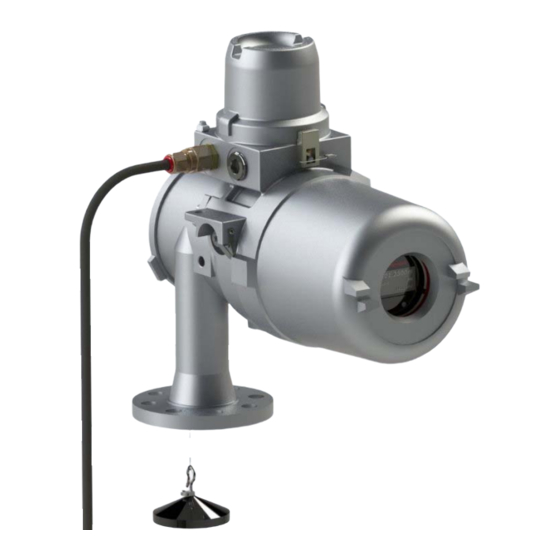
- Page 57 For installation see the Installation Manual for the 954 SmartServo FlexLine. NOTE: Contact our service department for any guidance if needed, through e-mail: [email protected] Figure 6-1 954 SmartServo FlexLine Part No.: 4417340 Revision 1 Service Manual 954 SmartServo FlexLine...
- Page 58 COMMISSIONING COMMISSIONING Checks before starting the commissioning Caution Keep screw thread from the compartment covers free from dirt. Grease them lightly with an acid-free grease before closing the instrument. When closing, turn the covers counter-clockwise until the thread clicks into place, then turn clockwise. Examine the mechanical and electrical installation after the 954 SmartServo FlexLine is installed on the tank.
- Page 59 Installation of measuring drum and displacer Tools It is recommended to use a HART SmartViewto load the different parameters. A tool set for commissioning and maintenance is available from Honeywell Enraf (see Figure 7-1) Figure 7-1. Part No.: 4417340 Revision 1...
- Page 60 COMMISSIONING Item Description Allen key 2 mm Allen key 3 mm Allen key 4 mm Allen key 5 mm Allen key 8 mm Drum bearing puller Test magnet Screwdriver for Allen key screws M4 Screwdriver for Allen key screws M6 10 Pipe wrench 27 mm 11 Tommy bar Figure 7-1...
- Page 61 COMMISSIONING Installation of measuring drum Remove the drum compartment cover (rear cover). Check whether the drum shaft is properly positioned in the drum. Remove the drum compartment cover (rear cover). Check whether the drum shaft is properly positioned in the ...
- Page 62 COMMISSIONING Installation of displacer If a density displacer is used, note the engraved displacer weight and displacer volume on a piece of paper for later use. Remove the test weight and attach the displacer to the wire through a mounting hatch. Note: If there is no mounting hatch available, the displacer can be installed by temporarily removing the gauge from the nozzle.
- Page 63 Allen key screw and turn the transport bracket the opposite way. Use screwdriver for Allen key screws M4 (item 8 of the Honeywell Enraf tool set). Fix the Allen key screw of the transport bracket. • Check the ...
- Page 64 COMMISSIONING Configuring FlexConn boards Introduction This chapter provides an overview of the commissioning information as per the FlexConn module. NOTE: Not all modules are always present. Commissioning a FlexConn module is performed by setting software parameters and the entities (see Service Manual Part No.: 4417340 Revision 1 954 SmartServo FlexLine...
-
Page 65
COMMISSIONING Entities), to the desired specific values. This can either be performed by using Engauge or HART SmartView (see HART SmartView). Text Conventions ☛ In contrast with explanatory text, all instruction text is preceded by a [Entity]
text is recognizable formatted. When - for instance - all required FlexConn module entities are commissioned, [Board Commissioned] entity displays... - Page 66 COMMISSIONING Enraf Fieldbus (HCI-BPM) 7.3.3.1 Introduction The Host Communication Instrument - Bi-Phase Mark (HCI-BPM) board is a communication module for the instrument (gauge). Figure 7-5 The HCI-BPM board with its isolation transformer As a result of any requirements on the cable quality, the connection of 10 to 15 devices per field bus, and cable lengths up to 10 km, the Bi- Phase Mark (BPM) signalling is used in many data transmission installations between various instrumentation and Communication...
- Page 67 COMMISSIONING The HCI-BPM module supports the following two protocols • The Enraf GPU protocol with its records and items (limited); • The Enraf FlexConn protocol with its entities. The module can communicate with the following: • 880 CIU prime • 858 CIU •...
-
Page 68
COMMISSIONING Name Value Range Default Value Explanation [Pressure units]
The unit in which pressure- related GPU records and (2 digits before items are displayed. separator) (3 digits before separator) [Density units] ... - Page 69 COMMISSIONING Product Level Measurement (TII-SRV) 7.3.4.1 Introduction The CAN-SERVO FlexConn board of the 954 SmartServo FlexLine runs the application firmware named TII-SRV. Figure 7-6 CAN-SERVO FlexConn board Part No.: 4417340 Revision 1 Service Manual 954 SmartServo FlexLine...
- Page 70 COMMISSIONING The CAN-SERVO board contains the following high level functions: Element Description Vibration sensor Sensor on the CAN-SERVO board measuring vibrations (acceleration). Stepper motor Motor to control the drum position in order to be able to raise or lower the displacer position in the storage tank. Encoder Transmits unique patterns in order to read out the motor position by the firmware.
- Page 71 COMMISSIONING Element Description temperature dependency of the magnetic field. By this magnet temperature measurement, the firmware compensates the level calculation. W&M jumper Weight and Measures jumper or switch located on every FlexConn board for protecting modification of W&M relevant entities (device parameters) and firmware. The W&M status is daisy chained to the other boards so only one of the boards need to be set to protect / seal status and all other boards will read that protect / seal status.
- Page 72 COMMISSIONING The TII-SRV firmware supports the following process data commands: • Water interface dip • Density tank profile dip • Density interface profile dip • Density-Water dip • Water-density dip The TII-SRV firmware supports the following displacer action and diagnostic commands: •...
- Page 73 COMMISSIONING The TII-SRV firmware supports the following configurable compensations: • Wire weight compensation • Mechanical hysteresis elimination • Magnet temperature compensation • Tank shell temperature compensation for high tanks • Compensation for wire expansion over temperature • Wire elongation compensation for free wire •...
- Page 74 COMMISSIONING 7.3.4.2 Board specific Name Value Range Default Value Explanation [Date and time] Shows the date and time of the RTC chip. [Write date and time] <2018,1,1,0,0,0> Here you write the actual date and time you want to set. [Set date and time] This command sets the new entered date and time to the RTC.
- Page 75 COMMISSIONING Name Value Range Default Explanation Value [Sales code] < 32 ‘-‘ > < 32 char’s > In production / commissioning the sales code can be set and can here also be read. [Device serial number] In production the device serial number can be set and can here be read.
-
Page 76
COMMISSIONING 7.3.4.3 Product level Name Value Range Default Value Explanation [Primary value] Shows the measured product level (I1 interface) as an innage value, with the following fields:
The level Good = All ok. Bad = Level fail. Uncertain = Level in reduced accuracy. - Page 77 COMMISSIONING Name Value Range Default Value Explanation [Primary value gain] <1.0> The calculated primary value can be multiplied with a desired gain. [Primary value offset] <0.0> The calculated primary value can be given an offset. [Secondary value] Shows the measured product level as an ullage value with the same fields as explained at the primary...
- Page 78 COMMISSIONING 7.3.4.4 Displacer level Name Value Range Default Value Explanation [Primary value] Shows the actual displacer position as an innage value. Fields, see product level [Primary value gain] See product level [Primary value offset] See product level [Secondary value] Shows the actual displacer position as an ullage value.
- Page 79 COMMISSIONING 7.3.4.5 Water level Name Value Range Default Value Explanation [Primary value] Shows the (dipped/searched) water level (I3 interface) as an innage value. Fields, see product level [Primary value gain] See product level [Primary value offset] See product level [Secondary value] Shows the (dipped/searched) water level (I3...
- Page 80 COMMISSIONING 7.3.4.6 Functional safety level Name Value Range Default Value Explanation [Functional safety level] Shows the functional safety level as a copy of the current product level. This level can be scanned from the CAN- SIL board, which will guard the overfill and underfill protection.
- Page 81 COMMISSIONING 7.3.4.7 Interface 2 level Name Value Range Default Value Explanation [Primary value] Shows the (dipped/searched) interface 2 level as an innage value. Fields, see product level [Primary value gain] See product level [Primary value offset] See product level [Secondary value] Shows the (dipped/searched) interface 2 level as an...
- Page 82 COMMISSIONING 7.3.4.8 Density Name Value Range Default Value Explanation [Primary value] Shows the calculated density value after a density profile or tank profile command. Fields, see product level [Primary value gain] See product level [Primary value offset] See product level [Secondary value] N.A.
-
Page 83
COMMISSIONING 7.3.4.9 Operational commands Name Value Range Default Value Explanation [Host command mode]
All With this entity the user can enable or disable the following commands: -Interface 1 -Interface 2 -Interface 3 -Block -Calibrate -Dip mode -Freeze -Interface profile -Lock test -Test gauge... -
Page 84
COMMISSIONING Name Value Range Default Value Explanation [Block mode]
With this entity the user can select whether the Block command remains active after the selected interface has reached the displacer. Set to continuous the Block command will remain active until another operational command with sufficient priority... - Page 85 COMMISSIONING Name Value Range Default Value Explanation [Lock test stop level] <0.0> Determines the level to which the displacer goes after a Lock to level, Lock test to level or Test command. [Lock to level] This command sends the displacer to the [Lock test stop level] and remains there.
- Page 86 COMMISSIONING 7.3.4.10 Special commands Name Value Range Default Value Explanation [Interface 1] This command activates the Servo to search for interface 1, the so called vapor-product interface, typically called the product level. It uses [Setpoint 1] and [Integration time 1] settings.
-
Page 87
COMMISSIONING 7.3.4.11 Configuration Name Value Range Default Value Explanation [Displacer type]
commissioning a displacer type can be selected from a list. [Measuring - Page 88 COMMISSIONING Name Value Range Default Value Explanation [Upper reference level] <27.0> The upper reference level is used to compute the ullage level. The ullage level is defined Ullage level = Upper reference level - innage level.. [Tank top level] <100.0> The Tank top level is used during a calibration test to determine if the calculated...
- Page 89 COMMISSIONING 7.3.4.12 Advanced Configuration Name Value Range Default Value Explanation [Displacer area] <0.0065> The displacer area must be entered at the point where the displacer touches the interface when the control loop is in balance. [Integration time 1] <2> Used to filter out (fast) [Integration time 2] <2>...
- Page 90 COMMISSIONING 7.3.4.13 Density configuration Name Value Range Default Value Explanation [Displacer volume] <110> The displacer volume. [Displacer weight] <223> The displacer weight in air. [Density scan direction]
density measurements are performed downwards (from e.g. - Page 91 COMMISSIONING Name Value Range Default Value Explanation [Default density tank <0.3> Determines the tank profile profile stop level] stop level until where the density measurements are performed. The highest is used, see next entity. [Density tank profile <-999.9999> Determines the tank profile stop level] stop level until where the density measurements are...
- Page 92 COMMISSIONING Name Value Range Default Value Explanation [Water density dip] This command first searches for the water level and after that performs a density measurement upwards. And then returns to the default operation mode. [Density water dip] This command first performs a density measurement downwards and after that searches for the water level.
- Page 93 COMMISSIONING 7.3.4.14 Compensation Name Value Range Default Value Explanation [Setpoint compensation]
Enable or disable the following compensations for the set point: -Wire weight Compensates for the wire weight -Unbalance Compensates for the unbalance of the drum and bearings -Density Compensates for the... - Page 94 COMMISSIONING Name Value Range Default Value Explanation [Level compensation]
-Wire temperature Compensates level for the expansion of the wire caused by temperature -Elongation free wire Compensates level for the expansion of the ... - Page 95 COMMISSIONING Name Value Range Default Value Explanation [Tank shell expansion <1.6E-05> Determines the coefficient] expansion coefficient of the tank shell material [Tank shell reference <20> Determines the temperature] reference temperature for the tank shell compensation [Tank shell ambient
... - Page 96 COMMISSIONING Name Value Range Default Value Explanation [Compensation Shows the hydrostatic hydrostatic deformation] deformation compensation [Compensation roof Shows the roof immersion] immersion compensation [Compensation level Shows the level drum temperature] compensation due to drum temperature. [Scanned product Shows the fetched temperature] product temperature from another board...
- Page 97 COMMISSIONING 7.3.4.15 Maintenance Name Value Range Default Value Explanation [Wire tension
With this entity the possibility protection] exists to enable or disable the wire tension high and low check. If enabled a high or low fail code will be generated if the tension exceeds the low or high thresholds. - Page 98 COMMISSIONING Name Value Range Default Value Explanation [Measured
- Page 99 COMMISSIONING Name Value Range Default Value Explanation [Go down] This command will let the displacer run down continuously. It can only be activated during maintenance mode. The command can be interrupted by Freeze or Go up command. No wire tension check! [Set to operational This command leaves the mode]...
- Page 100 COMMISSIONING Name Value Range Default Value Explanation [Check bearings <0.02> Determines the raise height at raise height] which the displacer is risen for the bearings test [Check bearings] This command activates the check bearing test [Measured bearings Shows the measured frequency, status] bearings status and timestamp after the command has been...
- Page 101 COMMISSIONING 7.3.4.16 Servo auto test Name Value Range Default Value Explanation [SAT upwards] With this command a manual SAT upwards can be performed. [SAT downwards] With this command a manual SAT downwards can be performed. [Autonomous SAT enable]
... - Page 102 COMMISSIONING Name Value Range Default Value Explanation [SAT frequency limit] <120> Determines the maximum frequency change when the displacer has been raised. [SAT intended interface]
Determines at/around which interface the SAT is performed. [SAT invalidate level] ... - Page 103 COMMISSIONING 7.3.4.17 Roof Immersion (RIC) Name Value Range Default Value Explanation [HART level addr Shows the level measured by the HART 11,12,13] probe at HART address 11,12,13, takelcd n into account the configured units. [Status] Shows the status of the calculated RIC compensation factor, which can be: No error RIC configuration parameters not...
- Page 104 COMMISSIONING Name Value Range Default Value Explanation [Total cross <0.0> Determines the total cross section area of section area roof] the floating roof (which will be less then total surface area of the product) [Interstice section <0.0> Determines the total interstice section area roof] between the floating roof and the tank wall.
- Page 105 COMMISSIONING Miscellaneous Name Value Default Value Explanation Range [Functional <32 times false> Shows which fields (and thus related licensed options) are enabled/set to true. options] Field 01: Density option Part No.: 4417340 Revision 1 Service Manual 954 SmartServo FlexLine...
- Page 106 COMMISSIONING Relay contacts (FII-DO) 7.3.6.1 Introduction The Field Interface Instrument - Digital Output (FII-DO) board has 4 software-controlled, electromechanical relays; see Figure 7-7. Note: only two relays, the low rated or high rated, are used not all 4 together. Figure 7-7 The relays and LEDs on the FII-DO board These relays are allocated to FlexConn functions as shown below: Function Number...
- Page 107 COMMISSIONING In addition to the board’s [Health] LED LE1, the LEDs LE2 and LE3 are available (see Figure 7-7). They can be associated to a relay, by setting [LED Association] entity. ☛ For a fail-safe level application, continue with section 7.3.6.10.
- Page 108 COMMISSIONING 7.3.6.3.2 Relay Mode Each individual relay can be set to be energized or de-energized during operation, by setting the [Relay Mode] entity to
respectively. If the [Relay Mode] entity is set to , the relay coil will be energized when the relay state is , and the relay coil will... - Page 109 COMMISSIONING 7.3.6.4 Alarm Mode Each individual relay can operate in one out of three modes, by setting [Alarm Mode] entity to either [PV Monitor], [Remote Control], [Not In Use]. 7.3.6.4.1 PV Monitor [PV Monitor] mode, each individual FII-DO-relay unit can monitor the Primary Value (PV) or Secondary Value (SV) of another board connected to the CAN bus, and either activate or deactivate the associated relay if a certain condition is...
- Page 110 COMMISSIONING ☛ [Local] [Monitor Mode] is to be set, skip to next bullet ( ). ☛ From the [Monitor Mode], select [Remote]. ☛ Select [Remote Threshold Source], set desired value. If the [Monitor Mode] is set to [Local], the scanned PV or SV value is compared against the value set in the [Threshold] entity.
- Page 111 COMMISSIONING If the [Status Behavior] is set to
, the respective relay will not be activated if the scanned PV or SV health is Bad or Uncertain. ☛ Set the [Status Behavior] entity either to , , or . NOTE:This behavior takes priority over the [Remote] [Local]... - Page 112 COMMISSIONING 7.3.6.4.5 Not in Use If an individual relay is not required in a particular application, the [Alarm Mode] entity must be set to
. Example: If a particular application requires only two relays to be used, say relay 1 and 2, then for relay 3 and 4 the [Alarm Mode] entities must be set to... - Page 113 COMMISSIONING 7.3.6.5.3 Acknowledge !Acknowledge! command will cause the specified relay to be physically deactivated, but the relay status will be set to !Acknowledged!. This command is only available in [PV Monitor] mode; see 7.3.6.4.1. This command can only be given when the concerned relay has already been activated.
- Page 114 COMMISSIONING 7.3.6.8 Commissioned Entities ☛ By using the table below, make sure all entities are commissioned. The [Commissioned] entity will display either
if the function is commissioned or if the function is not commissioned. To commission the function, the entities must be set in accordance with the table below. - Page 115 COMMISSIONING 7.3.6.9 Board Commissioned Entity [Board Commissioned] entity will display either
if all functions are commissioned or if any of the functions are not commissioned. ☛ If the [Board Commissioned] entity displays , check each function parameter again. Use the table from 7.3.6.8. - Page 116 COMMISSIONING FCI-HRT, HART master 7.3.7.1 Introduction The Field Communication Instrument - HART (FCI-HRT) board is a module that communicates with HART SmartView. ®1 The FCI-HRT board is a HART master module that enables hybrid- signal (both analog + digital) communication between the FlexConn instrument and a HART sensor and VITO-data processor module, which calculates average product- and Vapour temperatures, and optionally a water level.
- Page 117 COMMISSIONING With the HART protocol, an analog 4-20 mA signal can be combined with a digital Frequency Shift Keying (FSK) signal. See Figure 7-10 The analog and digital signals within the HART ® communication Figure 7-10 7.3.7.2 Software Description The FCI-HT board, being a functional module of the 954 SmartServo FlexLine, contains embedded software which enables it to collect data input from sensors via both the HART bus and the FlexConn CAN bus.
- Page 118 COMMISSIONING For HIMS density measurement system diagrams, see Figure 7-11 Figure 7-12 Figure 7-11 Standard HIMS density measurement system diagram Figure 7-12 Floating-roof or free-venting tank HIMS density measurement system diagram Service Manual Part No.: 4417340 Revision 1 954 SmartServo FlexLine...
- Page 119 COMMISSIONING As an alternative function, the FCI-HT board also allows the connection of up to 5 generic HART sensors operating in multi-drop digital mode or one generic HART sensor operating in analog mode. In the multi-drop digital mode situation, one or two of the generic HART sensors can be [P1 Pressure] Pressure], providing product pressure...
- Page 120 COMMISSIONING Example 2 2 HART density devices and 1 distance device can be connected. density device 1 allocated to Function 6 density device 2 allocated to Function 7 the distance device allocated to Function 3 Figure 7-13 Alternate system diagram multi-drop digital mode Service Manual Part No.: 4417340 Revision 1...
- Page 121 COMMISSIONING In analog mode, the connected HART device will be allocated to Function 1 through 7, depending on the type of HART device connected. Figure 7-14 Alternate system diagram multi-drop digital mode Part No.: 4417340 Revision 1 Service Manual 954 SmartServo FlexLine...
- Page 122 COMMISSIONING 7.3.7.3 Software Specifications 7.3.7.3.1 General The main function of the FCI-HT software is to measure HIMS product density, by connecting the FCI-HT board via the HART bus to 2 pressure sensors (P1 and P3), and via the FlexConn bus to a product level sensor and an optional water level sensor.
- Page 123 COMMISSIONING 7.3.7.3.2 P1 Pressure The FCI-HT software only accepts the Primary Value of a P1 pressure HART device in SI units kilo Pascals (kPa). ☛ Make sure the P1 pressure HART device is configured to output data in kilo Pascals (kPa). If not, correctly configure as yet, by using an appropriate HART configuration tool.
- Page 124 COMMISSIONING For the FCI-HT software to differentiate between a HART device malfunction and a HART device not actually installed, P1 pressure has the entity [P1 Installed] which must be set to either
if a P1 pressure HART device is actually fitted or if a P1 pressure HART device is not actually fitted. - Page 125 COMMISSIONING [Ambient Air If Relative pressure is selected, the value stored in the Pressure] entity is added to the measured pressure. If Absolute pressure is selected, no factor is added. The final result is available in the [Primary Value] entity. NOTE: Absolute pressure is used in the density calculation;...
- Page 126 COMMISSIONING • [Minimum HIMS Level] • [HIMS Level Hysteresis] • [Ambient Air Density] • [Tank Vapour Density] Figure 7-15 HIMS configuration principle To calculate HIMS density, the following valid data must be available: P1 pressure P3 pressure Product level ...
- Page 127 COMMISSIONING 7.3.7.4 Average Temperature & Water Level Measurement 7.3.7.4.1 Introduction The Field Interface Instrument - VITO1 (FII-VT) board is a VITO-data processor module, which calculates average product- and Vapour temperatures, and optionally a water level Figure 7-16 The FII-VT board with its planar transformer ®...
- Page 128 COMMISSIONING 7.3.7.4.2 VITO Interface Types For temperature and/or water level measurement, a proper VITO probe must be connected to the FII-VT module, using a VITO interface. There are 3 VITO interface types: 762 VITO MTT interface for 16-spot temperature measurement (thermocouple principle) and optionally a water bottom measurement...
- Page 129 COMMISSIONING Figure 7-17 Tank and temperature probe data (1) Part No.: 4417340 Revision 1 Service Manual 954 SmartServo FlexLine...
- Page 130 COMMISSIONING Figure 7-18 Tank and temperature probe data (2) Service Manual Part No.: 4417340 Revision 1 954 SmartServo FlexLine...
- Page 131 COMMISSIONING Product Temperature ☛ The following entities must be set by Engauge or HART SmartView for a correct functioning of the FII-VT module in an instrument. NOTE: Using Engauge, following entities are set within the Engauge Product temperature tab. Name Explanation Value Range Default...
- Page 132 COMMISSIONING Name Explanation Value Range Default [Alarm test enable] Enables (if activated, see
next listed entity) the simulation of one of the 4 alarms for a minute, by simulating the actual measured Primary Value is below or above the alarm threshold. - Page 133 COMMISSIONING Name Explanation Value Range Default [Alarm test enable] Enables (if activated, see
next listed entity) the simulation of one of the 4 alarms for a minute, by simulating the actual measured Primary Value is below or above the alarm threshold. - Page 134 COMMISSIONING ☛ The following entities can be set by Engauge or HART SmartView for a correct functioning of the FII-VT module in an instrument. Name Explanation Value Range Default [Water probe length] <0.5> The length of a water probe floating point number: <-x.x ..
- Page 135 COMMISSIONING 7.3.7.4.4 Commissioning Parameters for MRT or RTD Enraf Model VITO Type Description Multiple Resistance Thermometer MRT with up to 13 temperature elements with one spot element 3-spot 1..3 RTD spots in a 3-wire connection Resistance Temperature Detector multi-spot 1..14 RTD spots in a 2-wire connection Resistance Temperature Detector See Figure 7-19 and Figure 7-20 Figure 7-19...
- Page 136 COMMISSIONING Figure 7-20 Multiple Resistance Thermometer (MRT) parameters Service Manual Part No.: 4417340 Revision 1 954 SmartServo FlexLine...
- Page 137 COMMISSIONING Product Temperature ☛ The following entities must be set by Engauge or HART SmartView for a correct functioning of the FII-VT module in an instrument. NOTE: Using Engauge, following entities are set within the Engauge Product temperature tab. RTD 3 spots (see Figure 7-19 left side)
- Page 138 COMMISSIONING • MRT (see Figure 7-20) Name Explanation Value Range Default [Element type] See TABLE below. <---> 3 characters
[Number of elements] The number of elements <1 .. 14> <0> (resistors) an MRT probe [Lowest element offset] <80.0>... - Page 139 COMMISSIONING The following entities can be set by Engauge or HART SmartView for a correct functioning of the FII-VT module in an instrument. ☛ Check each entity for its correctness. Name Explanation Value Range Default [Product immersion depth] <0.5> The minimum required floating point number: <-x.x ..
- Page 140 COMMISSIONING Vapour Temperature NOTE: Using Engauge, following entities are set within the Engauge Vapour temperature tab. Some Vapour temperature settings are shared with Product temperature settings. The following entities can be set by Engauge or HART SmartView for a correct functioning of the FII-VT module in an instrument. ☛...
- Page 141 COMMISSIONING 7.3.7.4.5 Commissioning Parameters for the 765 VITO Water Probe For the entities to be set for the stand-alone 765 VITO water probe (see Figure 7-21 Figure 7-21 The model 765 VITO water probe Part No.: 4417340 Revision 1 Service Manual 954 SmartServo FlexLine...
- Page 142 COMMISSIONING Water Level ☛ The following entities must be set by Engauge or HART SmartView for a correct functioning of the FII-VT module in an instrument. Name Explanation Value Range Default [Maximum water capacity] <20000> The maximum capacity floating point number: <-x.x ..
- Page 143 COMMISSIONING Name Explanation Value Range Default [Alarm test] Activates and selects at the [No Alarm]
same time the Alarm test (if [High High alarm] enabled with the [Alarm test enable] [High listed before, and the Alarm] 4 alarm thresholds are [Low Alarm] properly set). - Page 144 COMMISSIONING Average Temperature Measurement (FII-RTD) 7.3.8.1 Introduction The Field Interface Instrument - Resistance Temperature Detector (FII- RTD) board is a sensor module for the instrument (gauge) and calculates average product, Vapour- and ambient temperatures. For accomplishing this, RTDs or MRTs must be directly connected to the FII-RTD module Figure 7-22 The FII-RTD board...
- Page 145 COMMISSIONING 7.3.8.2 Some Important Settings The FII-RTD can be tailored to the need of the customer by a lot of settings. See section Commissioning Some important settings of the FII-RTD in Board Specific tab are listed below. Setting Remarks ″ [Measurement type] ″...
- Page 146 COMMISSIONING 7.3.8.3 Some Important Features Temperature calculations can be: o Standard (just simple averaging the spot temperatures). (averaging the spot temperatures and taking into o Enhanced account the contribution of each spot in respect to its immersion). o Custom (as standard but then giving it a weighing factor). o A temperature-range check can be turned on.
- Page 147 COMMISSIONING See Figure 7-24. Low element usage NO EXCLUSION STATIC EXCLUSION DYNAMIC EXCLUSION (default) MPTs > = 2 elements MPTs > = 3 elements RTDs and MPT Product level Product level Product level > > <= Tempe Tempe Tempe <= <= rature rature...
- Page 148 COMMISSIONING • : This board can be electronically s ealed W&M Sealing via the software. A Notified Body can set his password via [W&M notified body seal password]. He can apply the seal by [W&M seal]. Here some data logging is filled in and setting the related password.
- Page 149 COMMISSIONING 7.3.8.4.2 Commissioning Parameters for MPT Temperature Calculations NOTE: Make sure the RTD/MPT jumper is set to MPT. ☛ The following entities must be set set by Engauge or HART SmartView for a correct functioning of the FII-RTD module in an instrument.
- Page 150 COMMISSIONING 7.3.8.4.3 Commissioning Parameters for MRT Temperature Calculations NOTE: Make sure the RTD/MPT jumper is set to MRT (= MPT position). ☛ The following entities must be set by Engauge or HART SmartView for a correct functioning of the FII-RTD module in an instrument. The default values are available after initialization of the non-volatile memory.
- Page 151 COMMISSIONING 7.3.8.4.4 Commissioning Parameters for All Types of Probes Engauge *Product temperature* Tab ☛ The following entities can be set set by Engauge or HART SmartView for a specific functioning of the FII-RTD module in an instrument. The default values are available after initialization of the non-volatile memory;...
- Page 152 COMMISSIONING Name Explanation Value Range Default [Element weighing factor] Each element can individually be floating point numbers: <1.0> <-x.x .. +x.x> given a weighing factor, which is applicable if the calculation method is CUSTOM. [Gauge temperature scale]
Determines whether the IPTS- ... - Page 153 COMMISSIONING Name Explanation Value Range Default [Element skipping] Enables or disables the fact that
elements can be skipped if an element is outside a temperature range. [Maximum skipped elements] <1,2> <1> The number of elements that can be skipped [Median filter] Enables or disables a ... - Page 154 COMMISSIONING Name Explanation Value Range Default [Gas immersion depth] <0.5> The minimum required floating point number: <-x.x .. +x.x> distance below an element before it is taken into account in the average Vapour temperature calculation [High High alarm] 4 Thresholds for activating floating point numbers: <+1.0E22>...
- Page 155 COMMISSIONING Engauge * Ambient temperature * Tab NOTE: Some settings for ambient temperature calculations are shared via the product temperature settings. ☛ The following entities can be set by Engauge or HART SmartView for a specific functioning of the FII-RTD module in an instrument.
- Page 156 COMMISSIONING HART Analog Outputs (HCI-HAO) 7.3.9.1 Introduction The Host Communication Interface – HART Analog Output (HCI-HAO) is a HART® slave module which communicates with the associated HART master over the HART bus. Figure 7-25 The HCI-HAO board The HART protocol is a bi-directional master-slave communication protocol, which is used to communicate between intelligent field instruments and host systems.
- Page 157 COMMISSIONING 7.3.9.2 Functional Description HCI-HAO is a HART slave module, which uses standard HART communication to communicate with HART-devices. This module makes use of the Bell 202 Frequency Shift Keying (FSK) standard to superimpose digital signals at a low level on the 4–20 mA analog signal.
- Page 158 COMMISSIONING All the HART universal commands and some common practice commands are supported by HCI-HAO. These are listed in the below tables. HART Universal Ccommands Command no. Description Read Unique Identifier Read Primary Variable Read Loop Current and Percentage of Range Read Dynamic variables and Loop Current Reserved Reserved...
- Page 159 COMMISSIONING 7.3.9.3 Other HCI-HAO features Planar transformer for galvanic isolation from HART bus. Malfunctioning of the HCI-HAO card (or any linked cards) is revealed on the HART bus by means of the device status. If any fatal errors occur during operation - which will run the program into an undesired situation - then a software reset (Warm Reset) is given to the HCI-HAO software.
- Page 160 COMMISSIONING Multi-drop mode supported to connect more than one HART- compatible device on HART bus. For operating the device in Multi- Drop mode, user needs to select the polling address to a non-zero value. Making the polling address to a non-zero value makes the output current mode to Fixed_4_20_MA (4 mA fixed).
- Page 161 COMMISSIONING NOTE: Commands used in the following calibration procedure can be executed either by using the CAN tool, the HART SmartView, or Engauge. Calibrate the analog output of the HCI-HAO as follows: ☛ Connect loop resistor at connector CN2 ☛ Power up HCI-HAO board ☛...
- Page 162 COMMISSIONING 7.3.9.5 Board Commissioning 7.3.9.5.1 Basic Configurable Entities Overview Basic configuration entities of the HCI-HAO board, which are configurable by using HART SmartView, are listed in the following table. Entity HART SmartView Data Type Type Default Function Display [PV Link board ID] Unsigned int Non-Volatile <0>...
- Page 163 COMMISSIONING 7.3.9.6 Commissioning ☛ The following entities must be set by Engauge or HART SmartView for a correct functioning of the HCI-HAO module in an instrument. Function Name Explanation Default Function Part Value [PV Link board ID] <0> Board ID of Other FlexConn Board Board Specific to be linked as PV to HCI-...
- Page 164 COMMISSIONING values for making the health for respective
Function or Board . However, the user is free to choose these values as per the requirement along with the rest of the entities. All the entities in the above table would be initialized to their default [init novram] values after command is given. - Page 165 COMMISSIONING Function Function Name Explanation Default Value Part Board Board Specific [QV Link function Function Instance of the <0> instance] linked QV board [Linked Primary Value] PV / SV value of linked PV <0> board in the set unit code [Linked Secondary PV value of linked SV <0>...
- Page 166 COMMISSIONING 7.3.9.7 Hardware Configuration 7.3.9.7.1 Jumper Allocation The following are typical jumper settings done on the HCI-HAO board. Jumper Connection Default Default Position Description Number Details Position Connections Short 2 & 3 W&M Entity Protection Short 1 & 2 Short 2 & 3 Password Read Protection Short 1 &...
- Page 167 COMMISSIONING TRL/2 Fieldbus (HCI-TRL) 7.3.10.1 Introduction The FlexLine 954 servo gauge is an inventory and custody transfer level gauge for storage tanks. It is a state of art technology design with highest reliability components and tested for the industrial level performance across global locations. This is designed to fit into existing Emerson gauging system as an attractive replacement with very minimal changes.
- Page 168 COMMISSIONING 7.3.10.2 System Description The FlexLine 954 servo gauges act as Rex gauges with the help of CAN- TRL/2 card. The CAN-TRL/2 communication card for FlexLine gauge is added to integrate to the Emerson system. The Rex Gauge and Rosemount Tankmaster (Emerson tank inventory) communicates over TRL/2 network and uses Modbus protocol.
- Page 169 COMMISSIONING NOTE: Ensure that the following devices/network/Hosts should be physically protected in a controlled area: Gauge and the SmartLink devices Networks in which the Gauge and the SmartLink nodes operate Hosts that connect to the Gauge and the SmartLink nodes operate 7.3.10.3 Before You Begin Migration 7.3.10.3.1 Device Mapping...
- Page 170 COMMISSIONING Possible combinations of cards in HART AO Relay Temp FlexLine Gauge Option 3 6 or 14 Option1: HRT-1(HART, Temp & AI as HART input), HCI-HAO (AO), FII-DO (Relay) - (3 cards) Option2: HRT-1(HART, & AI as HART input), FII-RTD (Temp), HCI-HAO (AO) & FII-DO (Relay) - (4 cards) Option3: HRT-1(HART &...
- Page 171 COMMISSIONING Possible combinations of cards in HART Relay Temp FlexLine Gauge Option 9 6 or 14 Option1: HRT-1(HART, Temp & AI as HART input), HCI-HAO (AO) - (2 cards) Option2: HRT-1(HART, Temp & AI as HART input), HCI-HAO (AO), FII-RTD (Temp) - (3 cards) Option3: HRT-1(AI1), HRT-2(AI2),HCI-HAO (AO), FII-RTD (Temp) - (4 cards)
- Page 172 COMMISSIONING 3. Select Save Database to File. The Save Database to File-LT-52 (Version 1.E4) dialogue box appears: 4. Browse and specify a folder to save the configuration settings from the database. 5. Click Save to save the configuration settings of the database. Service Manual Part No.: 4417340 Revision 1 954 SmartServo FlexLine...
- Page 173 COM24. On the SmartLink side the communication takes place by using the Non Isolated RS232 interface on the HCM- GPU module. Making new site in Engauge NOTE: Navigate to C:\Users\Public\Documents\Honeywell\ConfigFiles BoardDescriptor" and paste board descriptor files for FCM-TRL/2 and HCI-TRl/2. Part No.: 4417340 Revision 1...
- Page 174 COMMISSIONING HCM - GPU Module Figure 7-28 HCM-GPU Screen Open the Engauge tool from the PC where enguage is installed. Right click on HCM-GPU card.Select Commissioning. To read the current data of this TAB sheet, press the Read button. Instead, you can also select to press the Read All button available when extending the read function by the arrow at the right side of the read button).
- Page 175 COMMISSIONING Reset device button: All modules of the SmartLink are reset Reset board button: Only the HCM-GPU module is reset Software version: Current installed software version for the HCM-GPU module. The TAB sheet Board Specific provides host communication information as baud rate and turn around delay time (Refer to Figure "HCM-GPU Board Specific").
- Page 176 COMMISSIONING This setting is used for host systems that cannot switch directly from sending to receiving. The delay time can be set between 0 and 2000 msec. On the TAB sheet GPU-slave communication parameters can be set such as: GPU and FlexConn interface addresses, parity and modem control type (Refer to Figure "HCM-GPU Slave").
- Page 177 COMMISSIONING FlexConn interface address: The address for FlexConn communication, ranging from 1900 till 1999. Each SmartLink, connected to the same PC ComPort, must have a unique address. Similar as with the GPU interface address, if changed from default, also alter this FlexConn address at the SmartLink icon (one level higher).
- Page 178 COMMISSIONING 7.3.10.4.3 FCM-TRL/2 Module Figure 7-31 FCM-TRL/2 Screen Right click on FCM-TRL card. Select Commissioning. The TAB sheet Status gives information about the health of the TRL/2 module master Service Manual Part No.: 4417340 Revision 1 954 SmartServo FlexLine...
- Page 179 COMMISSIONING The TAB sheet Generic gives information on the installed software version, the board instance number and from there three commands can be given (Refer to "FCM-TRL/2 Specific"). Figure 7-32 Figure 7-32 FCM-TRL/2 Specific Reset device button:All modules of the SmartLink are reset TRL/2 Reset board button:Only the FCM- module is reset...
- Page 180 COMMISSIONING On the TAB sheet TRL/2 Modbus Master gauges modbus address can be set (Refer to "FCM-TRL/2 Modbus Master"). Figure 7-33 Figure 7-33 FCM-TRL/2 Modbus Master NOTE: You can enter maximum 20 gauges Modbus address for commissioning at a time. If you want to commission more gauges, delete the first 20 modbus address on the TRL2 Modbus page after commissioning them and add next 20 gauges address and commission them.
- Page 181 COMMISSIONING 30 till 59 for the second FCM- TRL/2 Module 60 till 99 for the third FCM- TRL/2 Module FlexConn instrument start address: FlexConn instrument stop address: When one FCM- TRL/2 Module is used in the SmartLink, the default start and stop addresses can be used. When two or three FCM- TRL/2 Modules are used in the SmartLink, a division must be made, like described above.
- Page 182 COMMISSIONING 7.3.10.5 Configuration of Gauge TRL/2 through Engauge You must configure the gauge TRL/2 through engauge. Follow the steps to configure the gauge TRL/2: 1. Connect the HCI TRL/2 card in FlexLine954 gauge. 2. Scan the gauge through SmartLink. 3. In the Engauge tool, right click on HCI-TRL board. Click on Commis- sioning 4.
- Page 183 COMMISSIONING a) Click Read. b) Click Send. 6. Click on Status tab. The page appears as follow: 7. Select True from the Commissioned [TRL/2 Modbus Slave] drop down menu. 8. Click Read. 9. Click Send. 10. Click on Generic tab. The page appears as follow: Part No.: 4417340 Revision 1 Service Manual...
- Page 184 COMMISSIONING 11. Check the Firware version is correct, and if you want to reset board and Novram you can reset using this tab. 12. Open the machine where Engauge tool is installed. 13. Create new site. Refer Installation and Operation Manual Engauge 2.6 - Professional.
- Page 185 COMMISSIONING 7.3.10.6 Firmware Upgrade 7.3.10.6.1 General The Firmware Upgrade can be done for two boards: 1. SmartLink TRL/2 (FCM-TRL) 2. Gauge TRL/2 (HCI-TRL) 7.3.10.6.2 Firmware Upgrade through Engauge NOTE: The Firmware upgrade process is same for both SmartLink TRL/2 and Gauge TRL/2 boards. When smartlink based direct upgrade is not possible, upgrade of gauge TRL2 firmware should be done through CAN-SD Card and not through FCU.
- Page 186 COMMISSIONING 4. Click on Browse to select the file. 5. Select .MHX file from the folder and click OK. 6. Click on Start. TRL/2 The Firmware is upgraded for SmartLink Service Manual Part No.: 4417340 Revision 1 954 SmartServo FlexLine...
- Page 187 COMMISSIONING 7.3.10.7 Firmware Upgrade of HCI-TRL/2 or FCM-TRL/2 through CAN-SD Card Follow the steps to upgrade firmware for HCI-TRL/2 or FCM-TRL/2 through CAN-SD card. 1. Insert the card in a card reader and connect it to PC. 2. Create a folder in the card and name it as “Firmware”. 3.
- Page 188 COMMISSIONING 7.3.10.8 Replacement Scenario 7.3.10.8.1 Replacing Rex Gauge The Rex gauges are replaced with CAN TRL/2 FlexLine 954 gauges. Follow the steps to replace Rex gauge: 1. Save backup of Rex configuration from Rosemount TankMaster. Refer to Section "Saving configuration in database"...
- Page 189 COMMISSIONING The page appears as follow: c) Select Upload Database. The dialogue box appears as follow: d) Click on Browse. Use the path where you saved the database. Part No.: 4417340 Revision 1 Service Manual 954 SmartServo FlexLine...
- Page 190 COMMISSIONING e) Select the file. f) Click on Upload. The configuration files are uploaded. 10. FlexLine reports data similar to Rex gauge which is replaced Service Manual Part No.: 4417340 Revision 1 954 SmartServo FlexLine...
- Page 191 COMMISSIONING 7.3.10.8.2 Possible Configuration Scenarios - FlexLine 954 Gauge The following schematics represents the possible configuration scenarios for connecting the 954 gauge interfacing to Rosemount TankMaster and Enraf Engauge tool with all possible intermediate devices. Figure 7-34 Configuration Scenario 1 NOTE: Configuration path: Engauge >...
- Page 192 COMMISSIONING Image: t.b.d Figure 7-35 Configuration Scenario 2 NOTE: Configuration path: Engauge > SmartLink > FCU > Gauge Communication path: TankMaster > FCU > Gauge Image: t.b.d Figure 7-36 Configuration Scenario 3 NOTE: Configuration path: Engauge > SmartLink > FCU > | Gauge Communication path: TankMaster >...
- Page 193 COMMISSIONING Image: t.b.d Figure 7-37 Configuration Scenario 4 NOTE: Configuration path: Engauge > SmartLink > Gauge Communication path: TankMaster > FBM > FCU > Gauge Part No.: 4417340 Revision 1 Service Manual 954 SmartServo FlexLine...
- Page 194 COMMISSIONING 7.3.10.9 Troubleshooting 7.3.10.9.1 Gauge Scan Issue 1. Scan the SmartLink and check for the gauge address mentioned in FCM-TRL/2 card. 2. If gauge address is not entered, enter the gauge address and GPU address and read all the board parameters. 3.
- Page 195 7.3.10.9.6 Smart link scan issue 1. Scan smart link if it shows network connection error. 2. Open “services” option in Engauge PC. 3. Select Honeywell Engauge Data service option, Right click and select Restart. 4. Scan Smart link from Engauge Tool.
- Page 196 COMMISSIONING 7.3.10.9.7 Gauge scan after Novram reset 1. Do Novram reset of HCI-TRL card. 2. Scan the gauge. The error message appears giving information about gauge scan fail. 3. Click on FCM-TRL card in smartlink and set GPU and Flexconn address of particular gauge as “0”. 5.
- Page 197 COMMISSIONING Part No.: 4417340 Revision 1 Service Manual 954 SmartServo FlexLine...
- Page 198 COMMISSIONING 7.3.11.2 Commissioning of TII-LCD For correct functioning of the TII-LCD module in the instrument, the following entities can be set by using either Engauge or HART SmartView. Name Value Range Default Value Explanation [Level type]
It determines level value to be displayed ... - Page 199 COMMISSIONING Name Value Range Default Value Explanation [LCD switch off time] <1 ..255> 3 digits <15> This is used to switch off the LCD to increase the life time of LCD. LCD will be switched of once time is elapsed from the time of start- up.
- Page 200 COMMISSIONING Name Value Range Default Value Explanation [LCD text] 60 Characters This field is used to display any maintenance string on the display. String entered in the entity will appear on the display if Start presenting Text command is issued. It will switch back to default Level and Temperature screen if...
- Page 201 COMMISSIONING 7.3.11.2.1 Commissioning screens of Engauge TII-LCD -> Commissioning -> Display tab option can be used to perform the required configuration required for correct functioning of LCD. Part No.: 4417340 Revision 1 Service Manual 954 SmartServo FlexLine...
- Page 202 COMMISSIONING Service Manual Part No.: 4417340 Revision 1 954 SmartServo FlexLine...
- Page 203 COMMISSIONING Part No.: 4417340 Revision 1 Service Manual 954 SmartServo FlexLine...
- Page 204 3. TII-LCD Level and Temperature Display screen 7.3.11.3.1 TII-LCD Start up Screen When the device is switched on, the LCD will display the Honeywell Logo of “Honeywell Enraf”. The first screen will perform a pixel test line by line. 7.3.11.3.2 Start up Screen 7.3.11.3.3 TII-LCD Initial Screen...
- Page 205 COMMISSIONING The correct tank name should be entered in the identification entity to display the tank name in the initial screen. Otherwise, it will display underscore characters in the place of the Tank name. The special character allowed in the Tank name is “_”. 7.3.11.3.4 TII-LCD Level and Temperature Display Screen This section describes the format of Level and Temperature screen and various screens based on the configuration of entities.
- Page 206 COMMISSIONING Level Screens with different unit configured The below table shows various screens when a different unit is configured using Engauge or HART SmartView. Level Units Screen Meter Inches Feet Fraction Level Screen with different Alarms The below table shows how different alarms will be reported by the LCD when it reads the alarms from the servo board.
- Page 207 COMMISSIONING Level Screen with Limit Switch Status The below table shows how the limit switch status is display on the LCD when Limit switch is reached in the servo. Motor Limit Switch Screen Reached Not Reached Level Screen with different displacer status The below table shows how the displacer movement is presented on the LCD.
- Page 208 COMMISSIONING Level Screen with different Operational status The below table shows how the different operational status reads from servo and is displayed on the LCD. Operational Status Screen No Status General CAN- SERVO board Fail Balance Test Block Calibrate Freeze Go Down Go Up Interface Profile...
- Page 209 COMMISSIONING Operational Status Screen Lock Test Measure Frequency Test Gauge Tank Profile Interface 1 Mode Interface 2 Mode Interface 3 Mode Dip Mode Water Density Dip Part No.: 4417340 Revision 1 Service Manual 954 SmartServo FlexLine...
- Page 210 COMMISSIONING Operational Status Screen Density Water Dip Test Lock Test To Level Lock To Level Check Bearings Process value killed Manual Process Value Service Manual Part No.: 4417340 Revision 1 954 SmartServo FlexLine...
- Page 211 COMMISSIONING Level Screen with different Level Type The below table shows how the level screens appear when different Level type is configured using Engauge or HART SmartView. Level Type Screen Innage Ullage Level Screen with Tenth Millimeter selection as Disable The below screen shows how the level value will appear when the Tenth Millimeter Selection units entity is configured as “Enable/Disable”...
- Page 212 COMMISSIONING Level Value with health status The below screen shows how the level value will appear for the different health status of level value. Health status Screen GOOD UNCERTAIN No Servo Board Service Manual Part No.: 4417340 Revision 1 954 SmartServo FlexLine...
- Page 213 COMMISSIONING Level Value with Board W&M intended The below screen shows how the level value will appear with Level unit and Level type when different options on the Board W&M intended are configured. Board Board health PV Health W&M Status Screen W&M of Servo...
- Page 214 COMMISSIONING Level and Temperature value screen with different contrast value The below screen shows how the level and temperature value screens will appear when different display contrast values are configured. Display contrast Screen 35 (default) Service Manual Part No.: 4417340 Revision 1 954 SmartServo FlexLine...
- Page 215 COMMISSIONING Level and Temperature Value screen with different Backlight brightness The below screen shows how the level and temperature screens will appear when different backlight brightness values are configured. Backlight Screen brightness 75(default) Level and Temperature Value with Decimal Separator The below screen shows how the level and temperature value screens will appear with different decimal separator.
- Page 216 COMMISSIONING Level and Temperature Value with Zero Format The below screen shows how the level and temperature value screens will appear with different zero format. Zero Format Screen format numerical 0 Format letter O Level and Temperature Value with different display format The below screen shows how the level and temperature value screens will appear with different zero format.
- Page 217 COMMISSIONING 7.3.11.3.5 LCD text This entity is used to enter string of 60 character to display it as maintenance message on the display. To display the string entered in the LCD text entity “Start presenting text” command should be used. To return back to default display screen “Stop presenting text”...
- Page 218 COMMISSIONING Temperature Value with different Health Status The below screen shows how the temperature value will appear with different health status. Health Status Screen GOOD ACTUAL GOOD MANUAL UNCERTAIN No Temperature Board Service Manual Part No.: 4417340 Revision 1 954 SmartServo FlexLine...
- Page 219 COMMISSIONING 7.3.11.3.6 Ambient Light Sensor TII-LCD is equipped with an Ambient Light Sensor which helps to increase the life-time of the LCD display. The LCD is switched off after LCD switch off time is expired. So, to activate the LCD again, cover the Ambient Light Sensor by hand during day time and flash light on the Ambient Light Sensor during night time.
- Page 220 COMMISSIONING Data refresh indicator LED Light Sensor Activation Indicator LED Board Health Indicator LED Figure 7-39: Picture of 3 LEDs 7.3.11.4 Error Handling Errors Possible Reason Resolution LCD not displaying data 1.LCD is not connected properly to 1) Perform Pixel test by CAN-LCD board issuing command from 2.Contrast value is set to Low value...
- Page 221 COMMISSIONING SIL overfill and underfill protection (FII-SIL) 7.3.12.1 Introduction Field Interface Instrument - Safety Integrity Level (FII-SIL) is an optional FlexConn board. The FII-SIL module provides overfill and underfill protection functionality certified and suitable for use in Safety Instrumented Systems at SIL 2 with systematic capability at SIL 3. It is used with the 954 SmartServo FlexLine tank gauge system.
- Page 222 COMMISSIONING The following safety categories are monitored continuously to determine whether a safe state should be activated, in the order listed, at a rate of at least once per second. Monitored Safety Categories Contact and analog output physical health Physical module health Contact and analog output functional health Product level health Product level overfill or underfill...
- Page 223 COMMISSIONING Safety Function Status Code User Action Latching Burnout Default Default PRODUCT LEVEL DATA CORRUPTED Service the Disabled High The product level value received from CAN-SERVO the tank gauge is corrupted. board PRODUCT LEVEL DATA TOO OLD Service the Disabled High The product level value received from CAN-SERVO...
- Page 224 COMMISSIONING Safety Function Status Code User Action Latching Burnout Default Default DATA MEMORY FAILURE Replace the Enabled High A failure of the FII-SIL data memory has CAN-SIL board occurred. CODE CHECKSUM FAILURE Replace the Enabled High The FII-SIL module code memory has CAN-SIL board become corrupted.
- Page 225 COMMISSIONING 7.3.13.2 Safety Shutdown Reason Codes The Safety Function Status Codes listed below have detail error information in the output’s Safety Shutdown Reason entity. Safety Function Safety Shutdown Reason Codes Status Code BOARD VOLTAGE MON ADC ERROR FAILURE Communication with the FII-SIL voltage monitor failed VOLTAGE MON POWER SUPPLY LO LIM_EXCEEDED The power supply voltage is below the lower limit.
- Page 226 COMMISSIONING Safety Function Safety Shutdown Reason Codes Status Code DATA MEMORY NOVRAM ENTITY BCC ERROR FAILURE The data read from non-volatile memory is corrupted. NOVRAM READ BACK ERROR The data written to non-volatile memory did not read back correctly. NOVRAM CORRUPT The non-volatile memory is corrupted.
- Page 227 COMMISSIONING Commissioning The FII-SIL module does not require the configuration of any entities for commissioning. By default, the board and all three output functions are already in the commissioned state. However, all outputs are in safe state, so configuration is necessary for the FII-SIL module to be useful.
- Page 228 COMMISSIONING (RO) = read only Contact 1 Name Value Range Default Value Description [Contact 1 Functional health of contact 1. Status Health] GOOD Any status other than GOOD UNCERTAIN will result in a safe state (RO) activation for contact 1. Status Category GOOD, ACTUAL VALUE GOOD, STORED VALUE...
- Page 229 COMMISSIONING Name Value Range Default Value Description [Contact 1 < 0 – 3.402823 × 10 > < 0.010 > A value relative to the threshold hysteresis] that will determine the point at (meters) which deactivation of a contact 1 safe state occurs after activation by an overfill or underfill condition.
- Page 230 COMMISSIONING Name Value Range Default Value Description [Contact 1 Stop Command Terminates an active contact 1 proof test] proof test. Upon termination, the normal process will resume and contact 1 will close. [Contact 1 proof < 1 – 3650 > <...
- Page 231 COMMISSIONING Contact 2 Name Permitted Values Default Value Description [Contact 2 Functional health of contact 2. Status health] GOOD Any status other than GOOD UNCERTAIN will result in a safe state (RO) activation for contact 2. Status Category GOOD, ACTUAL VALUE GOOD, STORED VALUE UNCERTAIN, INSTRUMENT...
- Page 232 COMMISSIONING Name Value Range Default Value Description [Contact 2 < 0 – 3.402823 × 10 > < 0.010 > A value relative to the hysteresis] threshold that will determine (meters) the point at which deactivation of a contact 2 safe state occurs after activation by an overfill or underfill condition.
- Page 233 COMMISSIONING Name Value Range Default Value Description [Contact 2 < 0 – 3.402823 × 10 > < 0 > The total number of contact 2 switch count] closures, or transitions from safe state to normal state. (RO) [Contact 2 start Command Initiates a contact 2 proof test proof test]...
- Page 234 COMMISSIONING Analog Output Name Permitted Values Default Value Description [Analog output Functional health of the Status health] GOOD analog output. UNCERTAIN Any status other than GOOD (RO) will result in a safe state activation for the analog Status Category output. GOOD, ACTUAL VALUE GOOD, STORED VALUE UNCERTAIN, INSTRUMENT...
- Page 235 COMMISSIONING Name Value Range Default Value Description [Analog output < Not used > < Overfill and The condition of product level safety function] underfill > relative to the threshold which < Overfill > will determine the activation of an analog output safe state, as <...
- Page 236 COMMISSIONING Name Value Range Default Value Description [Analog output < 0 – 3.402823 × 10 > < 0.010 > A value relative to the threshold hysteresis] that will determine the point at (meters) which deactivation of an analog output safe state occurs after activation by an overfill or underfill condition.
- Page 237 COMMISSIONING Name Value Range Default Value Description [Analog output Status: Status: H: Healthy safety function < H >, < O >, < U >, < W > < H > O: Overfill condition status] Status Code: Status Code: U: Underfill condition (RO) Defined in Section 7.3.13.1...
- Page 238 COMMISSIONING Name Value Range Default Value Description [Analog output Command Terminates an active analog stop proof test] output proof test. Upon termination, the normal process will resume and contact 2 will close. [Analog output < 1 – 3650 > < 1825 > The maximum time interval proof test permitted between analog...
- Page 239 COMMISSIONING Configuring the servo gauge To get the gauge fully operational several gauge and tank related entities must be configured properly (refer to Figure 7-40). Entity name Entity name Description (SmartView) [Displacer type] [Displacer type] Select the correct displacer type. This will configure (board) several displacer related parameters automatically.
- Page 240 COMMISSIONING Figure 7-40 Tank related level entities Alarm settings Alarms are applicable to all FlexConn sensor functions, like product level, displacer level, water level and density. It is important to know that 854 alarms, via B and L records are based on the displacer level.
- Page 241 A tank top reference stop is a mechanical device that can hold the displacer at a reproducible position when the displacer is pulled up. This device is placed above the motor limit switch high position. A Honeywell Enraf tank adapter can be provided with such a facility.
- Page 242 COMMISSIONING Level calibration using the top of ball valve If level dipping is not possible, the 954 SmartServo FlexLine can be calibrated using the top of a ball valve as reference point. Make sure the servo auto test downwards is disabled, else the servo gauge will end up in a SAT failure and will stop measuring level.
- Page 243 COMMISSIONING Interface measurement Interface 3 is used as product / water interface measurement (with interface 2 another interface can be measured). The set point must be set to such a value that half of the displacer volume is immersed in the water and the other half of the displacer volume is immersed in the product.
- Page 244 COMMISSIONING Height lower conical part: 6 mm Density product: 0.9 g/cm Setpoint 0.001* 223 - 105 0.45 0.5 0.12325 A level offset must be given as the displacer is now immersed for half of the volume in water. On product level the displacer is immersed less. The difference between both immersion depths must be given in the [Primary value offset] of the primary value of the water or interface2 level.
- Page 245 COMMISSIONING Entity name Entity name Description (SmartView) [Water interface dip] [Water interface dip] Performs water dip and returns to the default (Product level) operation once the water level is found: o Servo starts searching for water level o When water level is found it is copied to the Water Level PV o Servo returns to interface measurement dependent on the active operational mode...
- Page 246 COMMISSIONING 7.7.1.1 Wire weight The wire weight compensation requires one configuration parameter. This parameter is automatically set correctly when the correct [Measuring range and wire type] is chosen (refer to section 7.4) When < No measuring range selected>
selected the wire weight needs to be set manually: Entity name Default Value... - Page 247 COMMISSIONING Level compensations Level compensations directly affect the accuracy of the level measurement. Level compensation Description Magnetic coupling Compensates for the slip between inner and outer magnet. This compensation should be enabled when the gauge measures at different interfaces or when the ambient temperature change exceeds 10°C (18°F).
- Page 248 COMMISSIONING 7.7.2.1 Wire temperature The wire temperature compensation requires one configuration parameter. This parameter is automatically set correctly when the correct [Measuring range and wire type] is chosen (refer to section 7.4). When < No measuring range selected>
selected the wire temperature coefficient needs to be set manually: Entity name Default Value... - Page 249 COMMISSIONING For the tank shell compensation, the following entities should be set: Entity name Default Value Explanation Expansion coefficient of the tank shell. [Tank shell expansion < 16x10 [1/°C] > coefficient] Carbon steel: 12x10 [1/°C] Stainless steel: 16x10 [1/°C] Reference temperature for the tank shell [Tank shell reference <...
- Page 250 COMMISSIONING 7.7.2.4 Hydrostatic deformation Due to the liquid pressure on the tank shell, the tank shell will bulge. Because of this tank shell deformation, the tank roof moves downwards. Level gauges, which are installed on roof nozzles of fixed roof tanks, are influenced by this movement. The SmartServo FlexLine provides an innage compensation for this deformation.
- Page 251 COMMISSIONING If the rings have a different plate thickness, each ring must be calculated individually, where a and b are the distance of the top and bottom welding seam of each individual ring with respect to the liquid surface. Below follows an example of a calculation for a steel storage tank, diameter 83.82 m, product density of 1000 kg/m3, with the ring heights and wall thickness as per following: Example of tank ring measures...
- Page 252 COMMISSIONING The total tank shell deformation then becomes: δh = 0.19 + 0.45 + 0.72 + 0.75 + 0.76 + 0.77 + 0.78 + 0.72 + 21.945 0.90 = 6.04 mm. The above calculation is for a full tank (level 21.945 m). The tank shell deformation for the same tank, but then with a level of 21 metres is: Likewise, the other ring deformations are to be calculated.
- Page 253 COMMISSIONING The same procedure must be followed for all different levels, with for instance an interval of 1 meter. Then the following table is obtained: Example of hydrostatic deformation figures Level Deformation Level Deformation Level Deformation [mm] [mm] [mm] 0.54 2.64 0.01 0.69...
- Page 254 COMMISSIONING mechanisms must be enabled. However, under certain circumstances, they can or need to be disabled (refer to section 9.5) Entity name Entity name Default Description (SmartView) Value [Wire tension [Wire tension Enable Enables/disables the wire-protection. The motor is protection] stopped from moving in the wrong direction when the (Product level) wire tension gets too low or too high.
- Page 255 OPERATION OPERATION Repeatability test With the repeatability test the displacer is raised for approximately 60 mm (2.4”) and then returns to the product surface. During the test, the level dimension and level type on the display are replaced by exclamation marks (!!! !!!) and the status field (I1) changes to [TG].
- Page 256 OPERATION Entity name Entity name Description (SmartView) [Freeze] [Freeze] The displacer remains in its position even when the level (Product level) reaches the displacer position. [Block] [Block] The displacer stops at its present position, and (Product level) depending on the status of entity [Block mode], the displacer will only move up with an increasing level, or the block is cancelled when the level reaches the displacer position...
- Page 257 OPERATION Interface measurement The 954 SmartServo FlexLine can measure three different interfaces. Interface 1 (I1) is normally used to measure the product level. Interface 3 (I3) can be used to measure the product / water interface. Interface 2 (I2) is a setting for a special measurement (i.e. interface between two product layers).
- Page 258 OPERATION Servo Auto Test The Servo Auto Test (SAT hereafter) is an automatic safety related function meant to reduce the small risk of tank overfill or underfill caused by a failing servo gauge. Immediate after the gauge detects that tank loading has finished a SAT is executed to rule out (or detect) that the gauge is unable to measure the product level due to some failure (e.g.
- Page 259 OPERATION The default behaviour of the SAT can be influenced by means of several configuration entities. Entity name Entity name Default Description (SmartView) value [Autonomous [SAT enable] When set to 'SAT enable up’ a SAT will be started roughly 1 minute after tank loading has SAT enable] (Displ.
- Page 260 OPERATION Entity name Entity name Default Description (SmartView) value [SAT 0.180 kg During the SAT downwards, the weight of the immersed displacer in the product is measured and checked weight limit] against this limit. The measured weight must be smaller than [SAT immersed weight limit]. [SAT 120 Hz During the SAT upwards, the hysteresis is of the...
- Page 261 OPERATION Simple audit trail functionality is implemented by recording several SAT related parameters. Entity name Description < SAT status > Shows the status of the SAT (idle, 1st attempt, 2nd attempt, 3rd attempt, denied, fail, success). < SAT level last fail > Level at which a SAT last failed.
- Page 262 OPERATION Verify level calibration on top of ball valve If the top of the ball valve is used as reference point, the level calibration of the 954 SmartServo FlexLine can be verified. Make sure the servo auto test downwards is disabled, else the servo gauge will end up in a SAT failure and will stop measuring level.
- Page 263 MAINTENANCE MAINTENANCE Preventive maintenance There are several tests available to check whether maintenance is needed: • Check bearings o A short test that checks: the state of the bearings at one position on the drum • Measure displacer weight o A short test that checks: ...
- Page 264 MAINTENANCE Check bearings command The check bearings command measures the quality of the bearings at one position on the drum. The command first automatically raises the displacer by a configurable distance, performs a test and writes the result to an entity. Entity name Description [Check bearings raise height]...
- Page 265 The 954 SmartServo FlexLine is an explosion proof instrument with intrinsically safe output/input circuits. Modification to the instrument may only be carried out by trained personnel which is authorized by Honeywell Enraf. Failure to adhere to this will invalidate the approval certificate.
- Page 266 MAINTENANCE Balance test The balance test measures the unbalance and quality of the bearings over one drum rotation over a configurable number of points. The resulting unbalance data is used for the unbalance compensation for both level and density when enabled (refer to sections 7.7.1 10.2.3 Entity name...
- Page 267 MAINTENANCE The balance test results in several quality indicators that can be viewed in Engauge and partly on the SmartView. Entity name Entity name (SmartView) Description [Balance test result [Drum unbalance [kg]] The drum unbalance should be within 3 unbalance] (Product level) grams.
- Page 268 MAINTENANCE The red lines are only available after a balance test until the next reset. After a reset, only the blue line is still available (see Figure 9-2). Figure 9-2 Example of a smooth servo unbalance diagram (16 points) Figure 9-3 Example of a less smooth servo unbalance diagram (16 points) Figure 9-3 shows an example of a less smooth balance test diagram of 16 points.
- Page 269 MAINTENANCE Run-down test With the run-down test one can estimate the state of the bearings and the presence of obstructions over a certain range. The command will fill data arrays containing maximum and minimum measured frequency over 140 segments. Those segments are equally distributed between the start and stop position of the test.
- Page 270 MAINTENANCE Figure 9-5 Example of a smooth run-down diagram (segment size ~26 cm) Figure 9-5 shows an example of a smooth run-down test over a large distance. Because of the large segment size, the drum unbalance is no longer directly visible. The unbalance however is indirectly visible, because it causes the lines to be wider apart now.
- Page 271 MAINTENANCE Repeatability test (refer to section 8.1) If repeatability deteriorates (more than 1 mm) the drum bearings should be replaced (refer to section 0). Instrument covers Opening the instrument The joints between each cover and the housing are waterproof IP65. For this purpose, the covers of the servo, drum compartment and terminal compartment are fitted with O-rings (refer to Figure...
- Page 272 MAINTENANCE Figure 9-7 Drum Compartment Left-side image: Cross section of the drum compartment 954 SmartServo FlexLine medium pressure version. Right-side image: Cross section of the drum compartment 954 SmartServo FlexLine High pressure version and Chemical version Service Manual Part No.: 4417340 Revision 1 954 SmartServo FlexLine...
- Page 273 MAINTENANCE Removing the measuring drum Removing the drum from the housing requires no tools. Keep the drum, the outer magnet and the outside of the magnet cap thoroughly clean. To remove the drum, proceed as follows: Issue the Calibrate command to raise the displacer • If applicable close the ball valve and release the pressure gently.
- Page 274 MAINTENANCE Replacing the drum bearings Open the drum cover. Take out the drum shaft bushing. Replace the bearings, refer to figure below Install the bushing. Install drum and displacer. Close the cover. Figure 9-8 Replacing the drum shaft bearings Do not grease the carbon PTFE bearings. The drum bearings do not require any lubricant at all.
- Page 275 MAINTENANCE The electronic compartment Detailed description The electronic part of the 954 SmartServo FlexLine requires no special maintenance. However, a detailed description of the combination of the several parts is given in order to help you in case of software-updates or system enhancements.
- Page 276 MAINTENANCE Figure 9-9 Cross section of the electronic and terminal compartment Dismantling the electronic compartment Note: Whenever the force transducer and/or motor unit have been removed the force transducer must be recalibrated (refer to section Figure 9-5). To remove CAN-LCD board proceed as follows: 1.
- Page 277 MAINTENANCE Figure 9-10 Position of CAN-LCD screws, clamping bracket, and FlexConn board connectors To remove FlexConn boards, motor block and force tansducer proceed as follows: 1. Identify how the wiring is routed in general and the positions of option boards if there are any. This is helpful when replacing the components or subassemblies.
- Page 278 MAINTENANCE If the motor block needs to be removed, first remove the measuring drum (refer to section 9.3.1) 7. Remove the circlip from the main shaft. 8. Gently remove the motor from its shaft and remove the key. To remove mounting bracket and CAN-Servo Board proceed as follows: 1.
- Page 279 MAINTENANCE Calibrating force transducer After mounting a new force transducer or another motor-block the force transducer must be calibrated. The frequency of the force transducer must be calibrated with help of a set of accurate test weights of 25 g, 75 g, 150 g and 225 g, all ±0.1 g.
- Page 280 MAINTENANCE Switch off the wire protection before calibrating the force transducer: Entity name Entity name Default Description (SmartView) Value [Wire tension pr] Disable the wire-protection. This prevents [Wire tension Enable protection] (Product level) that under certain circumstances the 25 g calibration will be aborted.
- Page 281 MAINTENANCE Remove the test weights from the measuring wire and attach the displacer. Program the measured frequencies: Entity name Entity name Description (SmartView) [Frequency 0] [Frequency 0 [Hz]] Program frequency 0, measured with test weight of (Product level) 25 g. [Frequency 1] [Frequency 1 [Hz]] Program frequency 1, measured with test weight of...
- Page 282 MAINTENANCE Note: A faster method of calibration is using the commands [Measure frequency 0], [Measure frequency 1], [Measure frequency 2] and [Measure frequency 3] commands instead of the balance test command. The measured values are automatically entered in the corresponding entities ([Frequency 0], [Frequency 1], [Frequency 2] and [Frequency 3]).
- Page 283 MAINTENANCE Synchronizing the reference encoder After the installation of a new motor block, the internal reference encoder must be synchronized to the position of the reference encoder and the gauge starts with an error with status code e.g. ‘Find positions failed offset to big’...
- Page 284 DENSITY OPTION 10 954 Density option 10.1 Introduction Functional description A special software package for density measurement is available for the 954 SmartServo FlexLine gauge. This optional package offers the possibility to measure tank density profiles and interface density profiles. Tank Profile density measurement offers the possibility to measure the density at up to fifty spots in the product.
- Page 285 The apparent weight of the displacer is measured. Knowing the volume and the weight of the displacer, the observed density can be calculated. An average density will be calculated over all measured densities. The density data is transferred via the Honeywell Enraf field bus. Commissioning 10.2...
- Page 286 DENSITY OPTION Note: The measured displacer weight should not differ more than 0.1 grams from the engraved displacer weight (0.1 gram measuring error by the displacer weight results in a density error of 0.5 kg/m If it is more than 0.1 grams, re-calibrate the force transducer and/or check the drum unbalance.
- Page 287 DENSITY OPTION Tank profile measurement Interface Profile measurement Figure 10-1 Tank Profile and Interface Profile density measurement Settings for a tank profile measurement (command Tank profile) The following entities must be programmed before the 954 SmartServo FlexLine gauge can perform a Tank Profile density measurement. Part No.: 4417340 Revision 1 Service Manual 954 SmartServo FlexLine...
- Page 288 DENSITY OPTION Entity name Description [Tank profile start Refer to Figure 10-1. The distance from the liquid surface till the distance] middle point of the highest density measuring point. For a good density measuring result, the value must be at least 0.3 m (1 ft). [Default tank profile stop Refer to Figure...
- Page 289 DENSITY OPTION Corrections Entity [Air density] contains the ambient air density and is used to present the measured observed density as density in vacuum. If the density value is required as density in air, then entity [Air density] must be set to 0. Entity name Description [Air density]...
- Page 290 DENSITY OPTION Entity name Description [Index] Index 0 is the level closest to the bottom [density status byte] Refer to section 10.4.2 [density value] Measured servo density value; the calculated density at the corresponding level value. [level status byte 0] Refer to section 10.4.2 [level status byte 1]...
- Page 291 DENSITY OPTION Level status bytes level status byte 0 level status byte 1 Description Description general fail / default setting trajectory exceeds level product level; too small (TP [Tank profile start distance] only) no valid product level density trajectory stops below stop level (TP only) level / trajectory exceeds motor no valid start or stop levels (IP only)
- Page 292 TROUBLE SHOOTING 11 TROUBLE SHOOTING 11.1 Problems with displacer movement If the displacer is not running freely, for instance stuck against a stilling well, it can be controlled manually. Note: Be aware that measuring wire is unrolled from the measuring drum.
- Page 293 TROUBLE SHOOTING Informational status codes Numbers in the range 6336-6911 are informational status codes. Informational codes have a lower priority than warning or error codes, so if a warning or error is active the informational status isn’t visible. Status code Description Remarks (SmartView)
- Page 294 TROUBLE SHOOTING Warnings Numbers in the range 6272-6335 are warning codes. Warnings will set the status of the Primary value to UNCERTAIN. Status code Description Remarks (SmartView) (Engauge) 6273 No valid product level for E.g. because the displacer is not compensation measuring product level.
- Page 295 TROUBLE SHOOTING Status code Description Remarks (SmartView) (Engauge) 6292 Wrong HART units device address RIC warning 6293 Bad HART status device address RIC warning 6294 Bad HART status device address RIC warning 6295 Bad HART status device address RIC warning 6296 Weight in vapor bad for density tilt compensation...
- Page 296 TROUBLE SHOOTING Status code Description Remarks (SmartView) (Engauge) 6162 Drum slip occurred Probable slip of the inner and outer magnet. This can only be resolved by entering and exiting maintenance mode. Please check displacer level before continuing, there might be an offset of (multiples of) 11 cm.
- Page 297 TROUBLE SHOOTING Status code Description Remarks (SmartView) (Engauge) 6191 Encoder LED pin malfunction Hardware error. Malfunction of the LED of the reference encoder. 6208 Wire tension too high The wire tension is too high. The gauge will resume functioning when the wire tension issue is resolved (by e.g.
- Page 298 APPENDIX A 12 Appendix A: Article and part numbers Description Part number Measuring drum 27m incl. shaft and AISI316 wire S0854962 Measuring drum 37m incl. shaft and AISI 316 wire S0854963 Measuring drum 150m AISI 316 wire S0854325 Measuring drum 47m AISI316 0,2mm S0954303 Set bolts &...
- Page 299 APPENDIX A Description Part number Drum bearing set incl. circlips, bushing and drum shaft S0854953 Set of 20 pcs. drum bearings incl. circlips S0854955 Drum compartment cover - 854 ATG (M version) S0185583 FlexConn PCB: Relay output(FII-DO) 4xSPDT S0690904 FlexConn PCB: Power supply (PSS) S0690915 FlexConn PCB: RTD Spot (FII-RTD) S0690910...
- Page 300 APPENDIX A Service Manual Part No.: 4417340 Revision 1 954 SmartServo FlexLine...
- Page 301 APPENDIX B 13 Appendix B: Additional information on displacers Displacer type Part number Displacer area Displacer volume Displacer weight [kg] Carbon filled PTFE ø 25 mm S0815360 0.00049 0.223 ø 45 mm S0815343 0.0016 0.223 ø 90 mm S0815344 0.0064 0.223 ø...
- Page 302 APPENDIX B Service Manual Part No.: 4417340 Revision 1 954 SmartServo FlexLine...
- Page 303 SALES & SERVICE 14 Appendix C: ASCII table Table 14-1 ASCII table Part No.: 4417340 Revision 1 Service Manual 954 SmartServo FlexLine...
- Page 304 Copyright © 2019 - Honeywell All rights reserved. No part of this manual may be reproduced in any form, by print, photoprint, microfilm or any other means without the written permission from Honeywell. For more information To learn more about SmartLine...