Table of Contents
Quick Links
Table of Contents

Related Manuals for Honeywell HERMetic UTImeter Gtex Chem


Summary of Contents for Honeywell HERMetic UTImeter Gtex Chem
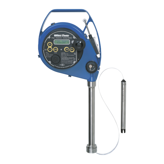
- Page 1 Operation and Service Manual for HERMetic UTImeter Gtex Chem for use in corrosive liquids Portable Gas Tight Electronic Gauging Device Ullage - Temperature - Interface detector Note 1: to identify the unit refer to section 2 Note 2: before using the instrument please read this book.
-
Page 2: Table Of Contents
1. Table of contents TABLE OF CONTENTS ............ 2 OPERATION..............27 BASIC RULES CONCERNING THE 5-KEY IDENTIFICATION OF YOUR EQUIPMENT ...... 4 CONTROL PAD ............. 27 SERIAL NUMBER ............ 4 SELECTING THE LANGUAGE ....... 28 ABBREVIATIONS ............. 4 SELECTING THE TEMPERATURE SCALE ..... 29 GENERAL INFORMATION.......... - Page 3 10.8 VERIFICATION AND CERTIFICATION 11.6 VISUAL INSPECTION FOR DAMAGED OR OF TAPES ............. 43 MISSING PARTS ........... 48 10.9 VERIFICATION AND ADJUSTMENT OF THE 11.7 COATED ALUMINIUM PARTS........ 49 READING INDEX............ 44 11.8 WINDING ACTION BECOMING STIFF ....49 10.10 TEMPERATURE VERIFICATION ......45 11.9 ELECTRICAL CHECKING OF THE TAPE ASSEMBLY............
-
Page 4: Identification Of Your Equipment
2. Identification of your equipment 2.1 Serial number Each HERMetic instrument is individually identified with a Identification plate 6 digits serial number starting with the letter G, example G10058. This serial number is printed on the identification plate that is located on top of the handle. See Figure 2-1. Figure 2-1 2.2 Abbreviations Some abbreviations are used to define the equipment. - Page 5 Display unit Mechanical housing Storage tube SS1 Gtex Gtex Chem Quick connector Q2 Visc: additional load for innage measurement or gauging viscous liquids Sensing probe ULTRA Figure 2-2...
-
Page 6: General Information
3. General information 3.1 Shipment note When returned to Enraf Tanksystem SA or any of its agreed Service Stations equipment must be contamination-free. The following parts should be included in the shipment: If it is determined that the Purchasers equipment is contaminated, it will be returned to the Purchaser at the •... -
Page 7: Certification
Classification Societies. If you need a copy of any of these certificates please contact: Enraf Tanksystem SA Rue de l’industrie 2 1630 Bulle, SWITZERLAND Telephone : +41-26-91 91 500 Telefax : +41-26-91 91 505 Web site : www.tanksystem.com E-mail : [email protected]... - Page 8 Service Request Customer’s address: ..............................................................................................................................................................Telephone: ..............................E-mail: ................................. Fax: ................................Type of unit or part: ............................................................Serial number: ............................Short description of trouble: ............................................................................................................................. Do you want a quotation before repair is started: ........ yes / no ........Repaired unit has to be returned to the following address: ..................................
-
Page 9: Worldwide Service Stations Network
4. Worldwide Service Stations network The updated list can be found on our website www.tanksystem.com COUNTRY ADDRESS TELEPHONE/FAX/E-MAIL SWITZERLAND ENRAF TANKSYSTEM SA Tel : +41-26-91 91 500 2, rue de l’Industrie Fax : +41-26-91 91 505 CH-1630 BULLE [email protected] CANADA PYLON ATLANTIC Tel : +1-902-4683344 A Div. - Page 10 The updated list can be found on our website www.enraftanksystem.com COUNTRY ADDRESS TELEPHONE/FAX/E-MAIL PORTUGAL CONTROLIS Tel : +351-21-2740606 Soc. Com. Equipamentos de Controlo, Fax : +351-21-2740897 Lda. Rua Conceiçao Sameiro Antunes, [email protected] 26E P-2800 COVA DA PIEDADE RUSSIA NPP “GERDA” Tel : +7-495-7558845 Vilisa Latsisa str.
-
Page 11: Recommendation For Safe Use
5. Recommendation for safe use This Operation and Service Manual is a guide in order In the absence of such instructions the following should to help the user to operate the instrument to our best be noted: knowledge. 6.1. If a metal sounding pipe is fitted beneath the Nevertheless the maker disclaims all responsibility and deck valve or tank is inerted, then ullaging, etc. -
Page 12: Functions - Key Features
6. Functions - Key Features This HERMetic instrument is a gas-tight portable multiple functions gauging system that is designed to perform under completely closed conditions in a single operation 3 measurements: a) Ullage (outage). Optionally innage is available¹. b) Oil/water Interface Level. Tape resolution: 1 mm (1/16 ”... -
Page 13: Description
7. Description 7.1 General Each HERMetic instrument is individually identified with a 6 digits serial number starting with the letter G, example G10058. This serial number is printed on the identification plate as shown on Figure 7-1. The HERMetic instrument is fitted with an ULTRA sensing probe. - Page 14 Window wiper LCD Display Display unit Window Buzzer Reading index Tape cleaner keys Crank Storage tube SS1 Quick connector Q2 Tape Tape adaptor Visc device for innage measurement Sensing probe ULTRA Figure 7-2 www.tanksystem.com...
-
Page 15: Ultra Sensing Probe
7.2 ULTRA sensing probe 7.2.2 Ullage detection The ullage detector consists of two piezoceramic plates and 7.2.1 Introduction electronic circuits. When the sensor head is immersed in a The ULTRA sensing probe consists of a stainless steel non-conductive liquid (oil or petroleum), the emitted ultrasonic tube terminated by a high-tech plastic head which cannot signal is detected by the receiver, coded and sent to the be removed from the tube. -
Page 16: Interface Detection
7.2.3 Interface detection sensor detects the presence of the liquid as well and the The principle consists of a conductivity measurement conductivity electrodes and associated electronic circuits between an active electrode and a grounded electrode. modulate the coded signal to generate the intermittent When the liquid is conductive (as water), the ullage beep. -
Page 17: Tape
7.3 Tape index. If the reading index is set up at the zero ullage level, the reading of the tape is identical to the ullage. The ETFE (TEFZEL) coated tape provides 3 main functions : • It contains 2 wires for transmitting the signal and the power between the display unit and the probe. -
Page 18: Tape Protection
7.4 Tape protection In that position the protection tube prevents closing the valve. When the tape is wound up the protection tube will The tape protection tube is a mechanical safety device which stay in position until it is pushed up by the sensing probe. prevents the valve from being closed as long as the sensing Before instrument is used check that the protection tube is probe is inside the tank. -
Page 19: Reading Index
7.5 Reading index Zero ullage 1200 Reference level of tank 1100 1000 Liquid level Reaction point Figure 7-9 The tape reading at the height of the reading index of the If the reading index is positioned below or above the reference instrument is indicating the distance between the reaction point level a positive or negative correction of the tape reading is and the reading index. -
Page 20: Tape Cleaner
7.6 Tape cleaner This HERMetic equipment is fitted with a tape cleaner that helps draining the liquid back to the tank when rewinding the tape. It is very easy to operate: • position “DOWN”: the wipers are not working, the tape is free;... -
Page 21: Gas Tightness
7.7 Gas tightness 7.9.2 Reference height and innage For measuring the reference height of a tank and innages All parts are assembled together with either gaskets or O-rings, the load allows the sensing probe to touch the dip/datum that makes the device completely tight. plate. -
Page 22: Examples Of Installation Of The Gauging System
8. Examples of installation of the gauging system 8.1 General The valves should be installed in such a way that the zero-ullage level coincides with the reading index level, so The gauging system consists of the HERMetic instrument and that no correction would be necessary. For achieving this it the associated HERMetic valve. -
Page 23: Example Of Installation On A Pipe, Connector Q2
8.2 Example of installation on a pipe, connector Q2 SS2 Q2 SS1 Q2 Tank Zero Ullage level Reading index Reading index 474mm 474mm TS supply Customer supply Flange Flange Tank Deck Figure 8-2 Valve designation C.2-SS; C.2-SS-W; C.2-SS-BL; C.2-SS-SEC Bottom connection thread or flange Boring 2”... -
Page 24: Example Of Installation On The Deck, Connector Q2
Example of installation on the deck, connector Q2 Tank Zero Ullage level SS2 Q2 SS1 Q2 Reading Reading index index 474 mm 474 mm Tank Deck Flange Flange Figure 8-3 Valve designation C.2-SS; C.2-SS-W; C.2-SS-BL; C.2-SS-SEC Bottom connection thread or flange Boring 2”... -
Page 25: Example Of Installation On A Pipe, Connector Q1
8.4 Example of installation on a pipe, connector Q1 SS1 Q1 SS1 Q1 Tank Zero Ullage level Reading index Reading index 460mm 460mm TS supply Thread Customer supply Flange Tank Deck Figure 8-4 Valve C.2-SS C.2-SS designation A.1-SS C.1-SS C.1-SS C.1-SS C.2-SS-W C.2-SS-W... -
Page 26: Example Of Installation On The Deck, Connector Q1
Example of installation on the deck, connector Q1 Tank Zero Ullage level SS1 Q1 SS1 Q1 Reading index Reading index 460 mm 460 mm Tank Deck Thread Flange Figure 8-5 Valve C.2-SS C.2-SS designation A.1-SS C.1-SS C.1-SS C.1-SS C.2-SS-W C.2-SS-W A.2-SS A.2,5-SS A.4-SS... -
Page 27: Operation
9. Operation 9.1 Basic rules concerning the 5-key control pad • pressing “-” allows to exit a menu, • pressing “enter” (later on named “E”) allows to enter a specific Apart from the “ON” / “OFF” keys that are self-explanatory, there menu. -
Page 28: Selecting The Language
9.2 Selecting the language English, German or French languages can be selected by following the sequences described in Figure 9-2. UTImeter Ver x.xx Battery ░ ░ ░ ░ ░ LED menu Init. ********* 25.94°C T. unit Settings Resol. Language English Deutsch Francais Figure 9-2... -
Page 29: Selecting The Temperature Scale
9.3 Selecting the temperature scale The temperature can be displayed either in Celsius or Farenheit degrees. Refer to Figure 9-3. UTImeter Ver x.xx Battery ░ ░ ░ ░ ░ LED menu Init. ********* 25.94°C T. unit > °C °F °C >... -
Page 30: Selecting The Temperature Resolution
9.4 Selecting the temperature resolution The temperature reading can be given with 1 or 2 digits after the dot. Select the appropriate resolution as shown on Figure 9-4. UTImeter Ver x.xx Battery LED menu ░ ░ ░ ░ ░ Init. ********* 25.94°C T. -
Page 31: Activating The Led
9.5 Activating the LED Refer to Figure 9-5. The LED can be activated on 2 modes: • one is temporary, it is automatically erased when the unit is switched off, in order to save the battery life; • the other is permanent, it will stay even is the unit is switched off. UTImeter Ver x.xx Battery... -
Page 32: Muting The Buzzer
9.6 Muting the buzzer When in measurement mode it is possible to mute the buzzer. • Press on “-”, UTImeter • Press on “-” again to reset the buzzer. Ver x.xx Battery IMPORTANT NOTE: in order to prevent any misuse of the equipment, there is an automatic reactivation of the buzzer ░... -
Page 33: Checking The Functions Before Using The Instrument
Checking the functions before using the 9.8.3 Ullage instrument Switch on the unit. The buzzer shall beep every 2 sec. Before installing the HERMetic instrument as described in Check the ullage in a glass of water. section 9.9, the following tests are recommended to ensure that the instrument is ready to work. -
Page 34: Installation Of The Instrument
9.9 Installation of the instrument • Switch on the equipment: a control beep is audible every 2 seconds. • This HERMetic equipment must be coupled to a certified • Put the tape cleaner on the “DOWN” position . Disengage the HERMetic valve. -
Page 35: Reference Height / Innage Measurement
9.12 Reference height / innage measurement the “DOWN” position during the final checking. Calculate the free water height by subtracting the index reading to the If the unit is fitted with the additional load (see Figure 9-8) then reference height. reference height / innage measurement are possible. -
Page 36: Temperature Measurement
9.13 Temperature measurement • When temperature has settled, record it. • Engage the tape cleaner on “UP” position . Raise the probe to • Install the HERMetic equipment as per 9.9 “Installation of the the next ullage level to be measured and repeat the procedure instrument”. -
Page 37: Checking The Battery
10.2 Checking the battery If the battery is too low, the unit will stop on the message “battery” as shown on Figure 10-2 and the buzzer tones continuously. Change the battery as per 10.3 “Battery Please note that in case you have to change the replacement”. -
Page 38: During Gauging
10.2.2 During gauging • Press on “+”, “Language” is displayed, When the unit is already switched on and working, it is always • Press on “+”, “Battery” is displayed, possible to see what power is left with the battery by entering •... -
Page 39: Battery Replacement
10.3 Battery replacement • Pull it gently out. • Change the battery (one-way only device). See Figure 10-4. • Push the battery holder back in its housing (one-way Warning : change the battery only in a non hazardous only). area. •... -
Page 40: Tape Replacement
10.4 Tape replacement • Disconnect the connecting plug (C) as shown on Figure 10-6 and remove the display unit. THE REPLACEMENT OF THE TAPE DOES NOT REQUIRE • Unscrew with the 2.5 Allen key the tape holder (G) by TO RE-CALIBRATE THE TEMPERATURE. removing the 2 screws (F) and the grounding cable (D) as shown on Figure 10-6. -
Page 41: Disconnecting The Tape From The Reel Axle
10.4.3 Disconnecting the tape from the reel axle • Put back the axle cover and its 3 securing screws. • Unlock the housing lid and remove it. • Follow the instructions of section 10.5 “Sensing probe • Remove the axle cover (3 screws to unscrew with the 2.5 replacement”... -
Page 42: Sensing Probe Replacement
10.5 Sensing probe replacement 1.5 mm Allen key THE REPLACEMENT OF THE SENSING PROBE DOES NOT REQUIRE TO RE-CALIBRATE THE TEMPERATURE tape wires NOR THE ULLAGE / INTERFACE. one-way only plug O-ring 10.5.1 Disconnecting the old sensing probe thread for securing screw •... -
Page 43: Display Unit Replacement
10.7 Display unit replacement 10.8 Verification and certification of tapes THE REPLACEMENT OF THE DISPLAY UNIT DOES NOT The tape has to be periodically inspected for breaks, kinks, wear REQUIRE TO RE-CALIBRATE THE TEMPERATURE. and illegible numbers. As the tape is a cable it might be necessary to check its 10.7.1 Disconnecting the old display unit electrical conformity. -
Page 44: Verification And Adjustment Of The Reading Index
Verification and adjustment of the reading • adjust the index to the value corresponding to the connector 10.9 index Q1 or Q2, as shown on Figure 10-12; • In case of a 2” connector (Q2) put back the clip and the To verify or to adjust the reading index, in particular after having collar. -
Page 45: Temperature Verification
10.10 Temperature verification (3) Insert the sensor, packing the ice gently about it. (4) Let it stand for half an hour to permit the sensor The temperature calibration curve is stored in the sensor temperature, the ice particles and the water to equilibrate. memory and cannot be modified. -
Page 46: Ullage/Interface Verification
10.11 Ullage/Interface verification position B The sensitivity of the instrument in ullage / interface cannot be position A adjusted. Both ullage and interface levels are set at the factory. Checking ullage and interface level detection The test liquid should be the one to be gauged. Fill in a container with appropriate liquid. -
Page 47: Trouble Shooting
11. Trouble shooting 11.1 Safety warning 3. Work shall be done only by maintenance personnel who has an experience with intrinsically safe equipment. As this equipment is designed and approved for use in an The design of the equipment is modular, i.e. in case of explosive area (intrinsic safe equipment), only authorized breakdown the customer can find out which modules have to be service stations and the factory are allowed to repair electronic... -
Page 48: Ullage And/Or Interface Troubles
11.4 Ullage and/or Interface troubles Symptom Origin Action Section Buzzer switched off or Press on “-” to reactivate it Pressing on “+” has no action The buzzer does not beep when Key-pad defective or 10.7 Change the display unit the unit is switched on Press on “+”: “Settings”... -
Page 49: Coated Aluminium Parts
11.7 Coated aluminium parts Test for open-circuit (continuity) • Disconnect the tape at the sensing probe side PA 11: Rilsan = blue, grey or yellow colour (see 10.4.1). The coating should be subject to regular and careful inspection. • Measure the resistance of each conductor of the The continued used of the apparatus should not be permitted tape (between red and red, white and white, etc.). -
Page 50: Specifications
12. Specifications General Specifications Accuracy of ullage-interface detection ±2 mm (± 0.08” approx.) Ullage, interface indication Audible or visible Tape length 15 m/50 ft, 30 m/100 ft, 35 m/115 ft Tape graduation Metric/English Tape resolution 1 mm / 1/16” Tape accuracy ±1.5 mm/30 m (±1/16”/100 ft approx.) Meets ISO 4512 and API MPMS Chap 3.1A requirements Diameter of probe (without load) -
Page 51: Spare Parts
13. Spare parts 13.1 How to proceed 3) With the assistance of the below table, identify its description, ex. “Sensor Ultra”. Each spare part is identified by the letters TS followed by a 5 For each order, please note the item number, its description and digits number, as for instance TS 10207 for the sensor or TS the required quantity. - Page 52 11227 Washer holder 11228 Screw cup 11235 Plate for battery holder 11240 Wiper holder 11246 Spring for battery holder 11247 Reel axle 11248 Gasket for battery holder 11249 Battery holder 11251 Axle cover 12100 O-Ring Ø26.7 x 1.78 11254 Storage tube 1’’ - Q1 without gaskets 11255 Storage tube 1’’...
-
Page 53: Spare Parts Drawings
40300 Socket head cap screw M3x8 40303 Socket head cap screw M4x12 40306 Socket head cap screw M3x10 40316 Socket head cap screw M3x6 40319 Socket head cap screw M3x30 40326 Socket head cap screw M3x20 40327 Socket head cap screw M3x25 40555 Spacer M-M M3x6/M3x8 40611... - Page 54 www.tanksystem.com...
- Page 56 www.tanksystem.com...
- Page 58 TS 12100 TS 11254 TS 11129 TS 11147 TS 11130 TS 11189 TS 11131 Figure 13-5: storage tube SS1-Q1 TS 10186, details www.tanksystem.com...
- Page 59 TS 12100 TS 20620 11255 Issue 2 TS 20618 TS 20538 Figure 13-6: storage tube SS1-Q2 TS 10187, details...
- Page 60 TS 12100 TS 11169 TS 11025 TS 11233 TS 20620 TS 40859 TS 20618 TS 11026 TS 20538 Figure 13-7: storage tube SS2-Q2 with load TS 10188, details www.tanksystem.com...
- Page 61 TS 40621 TS 11228 TS 11223 TS 40306 TS 12047 TS 40316 TS 12089 TS 11214 TS 11216 TS 11208 TS 40857 TS 12505 TS 11240 TS 12106 Figure 13-8: tape cleaner assembly TS 10206, details (the items TS 40621, TS 11228, TS 11223 are not included in the TS 10206 assembly; they shall be ordered separately)
-
Page 62: Valves Drawings
14. Valves drawings 14.1 Valves drawings list Refer to the table and find the drawing in next section. Description Valve C2-SS-W, 2” flange DUJ, weather cap 20291 10083 Valve C2-SS-SEC, 2” flange DUJ, security cover 20287 10082 Valve C2-SS-BL, 2” flange DUJ, blind cover 20288 10081 Valve C2-SS-BL, 2”... - Page 64 www.tanksystem.com...
- Page 66 www.tanksystem.com...
- Page 68 www.tanksystem.com...
- Page 70 www.tanksystem.com...
- Page 72 www.tanksystem.com...
- Page 74 www.tanksystem.com...
-
Page 75: Declaration Of Conformity
15. Declaration of conformity... - Page 76 Honeywell Enraf Tanksystem SA Rue de l’Industrie 2 1630 Bulle, Switzerland Phone: +41 (0) 26 91 91 500 Fax: +41 (0) 26 91 91 505 [email protected] 50457/GTEXCHEM/0808 August 2008 www.tanksystem.com © 2008 Honeywell International Inc.