Siemens SIMATIC S7-400H Manual
Automation system, fault-tolerant systems
Show thumbs
Also See for SIMATIC S7-400H:
- System manual (504 pages) ,
- Manual (210 pages) ,
- Manual (5 pages)
1
2
3
4
5
6
7
8
9
10
11
12
13
14
15
16
17
18
19
20
21
22
23
24
25
26
27
28
29
30
31
32
33
34
35
36
37
38
39
40
41
42
43
44
45
46
47
48
49
50
51
52
53
54
55
56
57
58
59
60
61
62
63
64
65
66
67
68
69
70
71
72
73
74
75
76
77
78
79
80
81
82
83
84
85
86
87
88
89
90
91
92
93
94
95
96
97
98
99
100
101
102
103
104
105
106
107
108
109
110
111
112
113
114
115
116
117
118
119
120
121
122
123
124
125
126
127
128
129
130
131
132
133
134
135
136
137
138
139
140
141
142
143
144
145
146
147
148
149
150
151
152
153
154
155
156
157
158
159
160
161
162
163
164
165
166
167
168
169
170
171
172
173
174
175
176
177
178
179
180
181
182
183
184
185
186
187
188
189
190
191
192
193
194
195
196
197
198
199
200
201
202
203
204
205
206
207
208
209
210
211
212
213
214
215
216
217
218
219
220
221
222
223
224
225
226
227
228
229
230
231
232
233
234
235
236
237
238
239
240
241
242
243
244
245
246
247
248
249
250
251
252
253
254
255
256
257
258
259
260
261
262
263
264
265
266
267
268
269
270
271
272
273
274
275
276
277
278
279
280
281
282
283
284
285
286
287
288
289
290
291
292
293
294
295
296
297
298
299
300
301
302
303
304
305
306
307
308
309
310
311
312
313
314
315
316
317
318
319
320
321
322
323
324
325
326
327
328
329
330
331
332
333
334
335
336
Table Of Contents
337
Table of Contents
Quick Links
SIMATIC
Automation System S7-400H
Fault-tolerant Systems
Manual
This manual has the order number:
6ES7988-8HA10-8BA0
Edition 07/2003
A5E00068197-07
Preface, Contents
Controllers
System and Operating Modes of the
Failure and Replacement of
Components During Operation
Appendices
Characteristic Values of Redundant
Programmable Logic Controllers
Differences Between Fault-Tolerant
Systems and Standard Systems
Function Modules and Communication
Processors Used on the S7-400H
Glossary, Index
1
2
3
4
5
6
7
8
9
10
11
12
13
A
B
C
D
E
F
Table of Contents

Related Manuals for Siemens SIMATIC S7-400H


Summary of Contents for Siemens SIMATIC S7-400H
- Page 1 Preface, Contents Fault-Tolerant Programmable Logic Controllers S7-400H Installation Options SIMATIC Getting Started Installation of a CPU 41x-H System and Operating Modes of the Automation System S7-400H S7-400H Fault-tolerant Systems Linking and Synchronizing Using I/O on the S7-400H Manual Communication Functions Configuring with STEP 7 Failure and Replacement of Components During Operation...
- Page 2 Trademarks SIMATIC, SIMATIC HMI and SIMATIC NET are registered trademarks of SIEMENS AG. Third parties using for their own purposes any other names in this document which refer to trademarks might infringe upon the rights of the trademark owners.
-
Page 3: A5E00068197
Preface Purpose of the manual The present manual is intended for persons involved in the areas of configuration, commissioning and servicing of programmable logic control systems. To help you get familiar with the product, we recommend that you start with the example in Chapter 3. - Page 4 Preface Changes compared to the previous version The current version of the ”Redundant Systems” manual contains the following changes compared with the previous version: • We have expanded the spectrum of redundant I/O modules. Note: You can identify the previous version of the ”Redundant Systems” manual by the number on the footer: A5E00068197-06.
- Page 5 Preface Online Help In addition to the manual, detailed support on how to use the software is provided by the online Help system integrated in the software. The Help system can be accessed using a number of interfaces: • The Help menu contains a number of commands: Contents opens the Help index.
- Page 6 Preface Note You require the following manuals and manual packages in order to program and commission an S7-400: Manual/ Contents Manual Package • Standard Software Installing and starting up STEP 7 on a programming device / PC • for S7 and M7 Working with STEP 7 with the following contents: STEP 7 Basic Managing projects and files...
- Page 7 Further Support If you have any technical questions, please get in touch with your Siemens representative or agent responsible. http://www.ad.siemens.com/automation/partner...
- Page 8 Technical Support 24 hours a day, 365 days a year Phone: +49 (0) 180 5050-222 Fax: +49 (0) 180 5050-223 E-Mail: adsupport@ siemens.com GMT: +1:00 Europe / Africa (Nuernberg) United States (Johnson City) Asia / Australia (Beijing) Authorization Technical Support and...
- Page 9 Preface Service & Support on the Internet In addition to our documentation, we offer our Know-how online on the internet at: http://www.siemens.com/automation/service&support where you will find the following: • The newsletter, which constantly provides you with up–to–date information on your products.
- Page 10 Preface Automation System S7-400H Fault-tolerant Systems A5E00068197-07...
-
Page 11: Fault-Tolerant Programmable Logic
Contents Fault-Tolerant Programmable Logic Controllers ......Redundant Programmable Logic Controllers in the SIMATIC Series ..Increasing System Availability . - Page 12 Contents 4.10 Consistent Data ..........4-40 4.10.1 Consistency for Communication Blocks and Functions...
- Page 13 Contents Communication Functions ..........Fundamentals and Basic Concepts .
- Page 14 Contents Modifying the System During Operation ........11-1 11.1 Possible Hardware Modifications...
- Page 15 Contents 11.6 Changing the CPU Parameters ........11-41 11.6.1 Step A: Changing the CPU Parameters Offline...
- Page 16 Contents Figures Operating objectives of redundant programmable logic controllers ..Universal automation solutions with SIMATIC ..... . . Example of redundancy in a network without malfunction .
- Page 17 Contents Example of an S7 connection ........Example of the number of resulting partial connections being dependent on the configuration .
- Page 18 Contents Tables LEDs of the CPUs ..........Positions of the mode selector .
- Page 19 Fault-Tolerant Programmable Logic Controllers This chapter contains an introduction to redundant and fault-tolerant programmable logic controllers. In Section Description On Page Redundant Programmable Logic Controllers in the SIMATIC Series Increasing System Availability Automation System S7-400H Fault-tolerant Systems A5E00068197-07...
- Page 20 At the same time there is a demand for fail-safe programmable logic controllers with the greatest degree of distribution possible. Redundant programmable logic controllers from Siemens have proved themselves in operation and thousands are in service. Perhaps you are already familiar with one of the fault-tolerant systems such as the SIMATIC S5-115H and S5-155H, or the fail-safe S5-95F and S5-115F systems.
- Page 21 Fault-Tolerant Programmable Logic Controllers Why do we have fault-tolerant programmable logic controllers? The objective of using high-availabilty programmable logic controllers is a reduction of production losses. It does not matter whether the losses are caused by an error or as a result of maintenance work. The higher the costs of a stoppage, the more worthwhile it is to use a fault-tolerant system.
- Page 22 Fault-Tolerant Programmable Logic Controllers Increasing System Availability The S7-400H programmable logic controller meets these high requirements for availability, intelligence and distribution that are required of state-of-the-art programmable logic controllers. Further, it features all the functions for acquiring and preparing process data and for controlling, regulating and monitoring units and systems.
- Page 23 Fault-Tolerant Programmable Logic Controllers Redundant nodes Redundant nodes represent the fault tolerance of systems with redundant components. The independence of a redundant node is given when the failure of a component within the node does not result in reliability constraints in other nodes or in the entire system.
- Page 24 Fault-Tolerant Programmable Logic Controllers Automation System S7-400H Fault-tolerant Systems A5E00068197-07...
-
Page 25: S7-400H Installation Options
S7-400H Installation Options The first part of the description starts with the basic configuration of the fault-tolerant S7-400H programmable controller and the components making up the S7-400H base system. We then describe the hardware components with which you can expand this base system. The second part describes the software applications with which you can configure and program the S7-400H. - Page 26 S7-400H Installation Options Figure 2-1 shows an example of the configuration of an S7-400H with common distributed I/O and a connection to a redundant system bus. On the next few pages we will describe step by step the hardware and software components necessary for configuring and operating the S7-400H.
- Page 27 S7-400H Installation Options Base System of the S7-400H Hardware of the base system By base system of the S7-400H we mean the minimum configuration of the S7-400H. The base system consists of all the requisite hardware components that make up the fault-tolerant control system. Figure 2-2 shows the components in the installation.
- Page 28 S7-400H Installation Options Mounting rack for S7-400H We recommend you the UR2-H mounting rack for the S7-400H. The mounting rack makes it possible to configure two separate subsystems, each containing nine slots, and is suitable for installation in 19” cabinets. Alternatively, you can also configure the S7-400H on two separate mounting racks.
- Page 29 S7-400H Installation Options I/O Modules for S7-400H For the S7-400H you can use virtually any of the input/output modules featured in the SIMATIC S7 system range. The I/O can be used in • central controllers • expansion units • distributed over PROFIBUS DP. The function modules (FMs) and communication processors (CPs) that can be used in the S7-400H will be found in Appendix E.
- Page 30 S7-400H Installation Options Communication For communication tasks on the S7-400H you can use almost any communications components offered in the SIMATIC system range. This applies to communication components used either with central I/O or distributed I/O such as • system busses (Industrial Ethernet) •...
- Page 31 S7-400H Installation Options Tools for Configuration and Programming Similar to the S7-400, the S7-400H is also configured and programmed with STEP 7. After configuration with STEP 7, you treat the S7-400H as a normal S7-400 system. For you this means that you can use your full knowledge of the SIMATIC S7 and, for example, only have to take minor constraints into account when writing your user program.
- Page 32 S7-400H Installation Options Specific Blocks for S7-400H Apart from the blocks that can be used on both the S7-400 and the S7-400H, there are further additional blocks for the S7-400H with which you can influence the redundancy functions. You can react to redundancy errors of the S7-400H with the following organization blocks: •...
-
Page 33: Getting Started
S7-400H Installation Options Documentation The following illustration provides an overview of the documentation for the various components and applications of the S7-400H automation system. Subject Documentation Hardware: S7/M7-400 standard documentation Redundancy–capable power supply Installation Module rack UR2-H Module Specifications Instruction List IM 153-2 ET 200M Distributed I/O Fault tolerant-specific programming:... - Page 34 S7-400H Installation Options Automation System S7-400H Fault-tolerant Systems 2-10 A5E00068197-07...
- Page 35 Getting Started This guide walks you through the steps that have to be performed to commission the system by means of a specific example and results in a working application. You will learn how an S7-400H programmable logic controller operates and become familiar with its response to a fault.
- Page 36 Getting Started Requirements The following requirements must be met: A permitted version of the STEP 7 standard software and the “S7 Fault-Tolerant System” option pack are correctly installed on your programming device (refer to Section 9.1). You must have the modules required for the hardware configuration: •...
- Page 37 Getting Started Configuring Hardware and Starting Up the S7-400H Installing Hardware To configure the S7-400H as illustrated in Figure 3-1, perform the following steps: Rack 0 Rack 1 S7-400H PLC ET 200M distributed I/O Figure 3-1 Hardware configuration 1. Configure the two subunits of the S7-400H PLC as described in the S7-400, M7-400 Programmable Controllers, Hardware and Installation/Module Specifications manuals.
- Page 38 Getting Started 3. Connect the programming device to the first fault-tolerant CPU (CPU0). This CPU should be the master CPU of the S7-400H. 4. A high-quality RAM test is performed after power on. It requires approximately 8 seconds per megabyte of RAM. During this time the CPU cannot be addressed via the multipoint interface and the STOP LED flashes.
- Page 39 Getting Started Note You can start and stop the S7-400H programmable logic controller using the programming device too. You will find more information on this in online Help of the S7-400H options package. Examples of Fault-Tolerant System Response to Faults Example 1: Failure of a central processing unit or power supply Initial situation: The S7-400H is in redundant system mode.
- Page 40 Getting Started Automation System S7-400H Fault-tolerant Systems A5E00068197-07...
-
Page 41: Installation Of A Cpu 41X-H
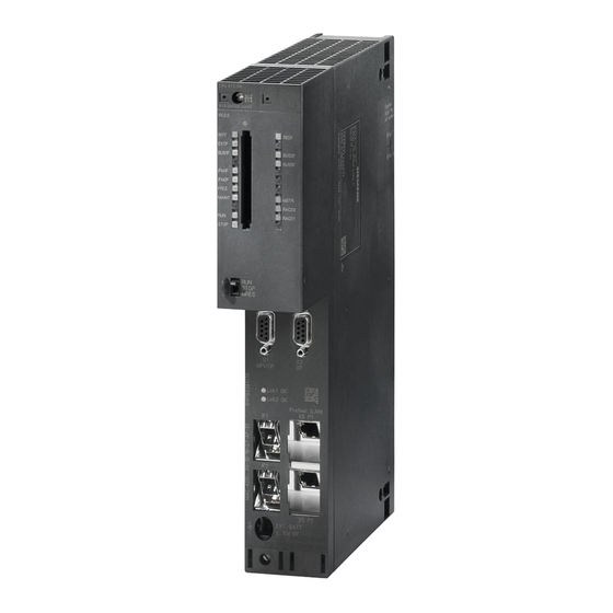
Installation of a CPU 41x-H Chapter Overview In Section Description On Page Controls and Indicators of the CPUs Monitoring Functions of the CPU Status and Error LEDs Mode selector 4-11 Memory Expansion 4-15 Multipoint Interface (MPI) 4-24 PROFIBUS DP interface 4-25 Overview of the Parameters for the S7-400 CPUs 4-26... - Page 42 Installation of a CPU 41x-H Controls and Indicators of the CPUs Operation and Display Elements of the CPU 414-4H/417-4H Module designation, version, abbre- viated order number and firmware version V3.0.0 REDF, IFM1F, IFM2F, INTF, EXTF, BUS1F, BUS1F MSTR, RACK0, RACK1 BUS2F BUS2F, FRCE, RUN, STOP IFM1F...
- Page 43 Installation of a CPU 41x-H Table 4-1 LEDs of the CPUs Color Meaning INTF Internal fault EXTF External fault FRCE yellow Active force request green RUN mode STOP yellow STOP mode BUS1F Bus fault at MPI/PROFIBUS DP interface 1 BUS2F Bus fault at PROFIBUS DP interface 2 MSTR yellow CPU leads the process...
- Page 44 Installation of a CPU 41x-H Interface for Expanded Memory CPU 417-4H provides an additional interface for expanded memory. This make it possible to expand the working memory. (See Chapter 4.5 ) Slot for Interface Modules The H synchronization module can be inserted into this slot. MPI/DP Interface You can connect the following devices to the MPI of the CPU, for example: •...
- Page 45 Installation of a CPU 41x-H Connecting External Backup Current to the “EXT. BATT.” Socket You can use one or two backup batteries – depending on the module type – in the power supply modules of the S7-400 to do the following: •...
- Page 46 Installation of a CPU 41x-H Monitoring Functions of the CPU Monitoring and Error Messages The CPU hardware and the operating system have monitoring functions that ensure that the system functions correctly and that there is a defined response to an error. A number of errors will also produce a response from the user program. The following table gives you an overview of possible errors, their causes and the responses of the CPU.
- Page 47 Installation of a CPU 41x-H Type of Cause of Error Response of the Operating Error LED Fault/Error System • Priority class Priority class is called, but the OB 85 call error corresponding OB is not available. If the OB is not loaded: The CPU INTF •...
- Page 48 Installation of a CPU 41x-H Status and Error LEDs LEDs RUN and STOP The RUN and STOP LEDs provide information about the currently active CPU operating status. Meaning STOP CPU is in RUN mode. CPU is in STOP mode. The user program is not processed. Restart and warm restart/reboot is possible.
- Page 49 Installation of a CPU 41x-H LEDs INTF, EXTF and FRCE The three LEDs, INTF, EXTF and FRCE, provide information about the errors and special events during running of the user program. Meaning INTF EXTF FRCE An internal error has been detected (programming or parameter assignment error).
- Page 50 Installation of a CPU 41x-H LEDs IFM1F and IFM2F The LEDs IFM1F and IFM2F indicate errors that occur in the first and second module interfaces. Meaning IFM1F IFM2F An error has been detected at module interface 1. An error has been detected at module interface 2. H = LED lights up;...
- Page 51 Installation of a CPU 41x-H Mode Selector Function of the Mode Selector Using the mode selector, you can put the CPU in RUN/RUN-P or STOP mode or reset the memory of the CPU. STEP 7 offers further options for changing the mode.
- Page 52 Installation of a CPU 41x-H Table 4-2 Positions of the mode selector Position Explanation RUN-P If there are no startup problems or errors and the CPU was able to go into RUN, the CPU executes the user program or runs with no load. It is possible to access the I/O. The key cannot be removed in this position.
- Page 53 Installation of a CPU 41x-H Table 4-3 Protection levels of a S7-400 CPU Protection Function Switch Position Level • All programming device functions are permitted RUN-P/STOP (default setting). • It is permissible to load objects from the CPU into programming device. In other words, only read programming device functions are permitted.
- Page 54 Installation of a CPU 41x-H Reboot (Warm Restart) Following a reboot, the user program is restarted from the beginning. The retentive data and the contents of the data blocks are retained. Operation Sequence for Reboot/Warm Start 1. Turn the switch to the STOP setting. Result: The STOP LED lights up.
- Page 55 Installation of a CPU 41x-H Expanded Memory Determining Memory Requirements with the SIMATIC Manager You can have the block length displayed offline in the dialog field “Properties - Block folder offline” (Blocks –> Object Properties –> Blocks tab). The following lengths are shown in the offline view: •...
- Page 56 Installation of a CPU 41x-H Generating block–specific messages Memory requirements of SFBs for generating block–specific messages, in contrast to the specifications in the Online Help and electronic manual: SFBs for generating block–specific messages generally require a communication buffer in the CPU work memory (code area), the size of which is also dependent on the length of the associated values.
- Page 57 Installation of a CPU 41x-H 4.5.1 Expanding Load Memory with Memory Cards Order Numbers The order numbers for memory cards are listed at the end of this chapter with the technical specifications. Installation The memory card is slightly larger than a credit card and protected by a strong metal casing.
- Page 58 Installation of a CPU 41x-H What the Memory Card Contains The following data can be stored in the memory card: • User program, i.e. blocks (OBs, FBs, FCs, DBs) and system data • Parameters that determine the behavior of the CPU •...
- Page 59 Installation of a CPU 41x-H RAM Card When you use a RAM card, you have to plug this into the CPU to load the user program. The user program is loaded with the help of the programming device (PG). You can load the entire user program or the individual parts such as FBs, FCs, OBs, DBs, or SDBs into the load memory in STOP mode or in RUN-P mode.
- Page 60 Installation of a CPU 41x-H Changing Memory Cards To change the memory card, follow the steps outlined below: 1. Set the CPU to STOP. Note If the memory card is not removed in the STOP mode, the CPU goes to the STOP state and the STOP indicator flashes every 3 seconds to prompt you to carry out a memory reset.
-
Page 61: S7-400H
Installation of a CPU 41x-H Technical Specifications Name Order Number Current BackupCurrents Consumption at 5 V typ. 1 mA MC 952 / 256 Kbytes / RAM 6ES7 952-1AH00-0AA0 typ. 35 mA max. 40 mA max. 80 mA typ. 3 mA MC 952 / 1 Mbyte / RAM 6ES7 952-1AK00-0AA0 typ. - Page 62 Installation of a CPU 41x-H 4.5.2 Expanding the Working Memory of the CPU 417-4 H with Memory Modules Memory Expansion The working memory of the CPU 417-4 H can be expanded with memory modules. The following points are important: 1. When only one module is used it has to be inserted in slot 1. 2.
- Page 63 Installation of a CPU 41x-H Note The connectors to accept the memory cards are coded (see Figure 4-5). Do not apply force when fitting the memory cards. Lightly press the guide supports out to remove the memory cards (see Figure 4-5). Slot 1 Slot 2 Figure 4-4...
- Page 64 Installation of a CPU 41x-H Multipoint Interface (MPI) Connectable Devices You can, for example, connect the following nodes to the MPI: • Programming devices (PG/PC) • Operation and monitoring devices (OPs and TDs) • Additional SIMATIC S7 programmable controllers Some connectable devices take the 24 V supply from the interface. This voltage is available there in a non-isolated form.
- Page 65 Installation of a CPU 41x-H PROFIBUS DP Interface Connectable Devices All standard DP slaves can be connected to the Profibus DP interface. The CPU is the DP master and is connected to the passive slave stations or other DP masters through the PROFIBUS-DP field bus. Some connectable devices take the 24 V supply from the interface.
- Page 66 Installation of a CPU 41x-H Overview of the Parameters for the S7-400 CPUs Default Values All the parameters have default settings at delivery. These defaults, which are suitable for a whole range of standard applications, mean that the S7-400 can be used immediately without the need for further settings.
- Page 67 Installation of a CPU 41x-H Parameter Assignment Tool You can set the individual CPU parameters using “Configuring Hardware” in STEP 7. Note If you make changes to the existing settings of the following parameters, the operating system carries out initializations like those during cold restart. •...
- Page 68 Installation of a CPU 41x-H Changing the Operating Mode of an H CPU To change the operating mode of an H CPU, carry out one of following procedures depending on the operating mode you wish to change to and the module rack number of the CPU: Changing from Redundant to Single Mode 1.
- Page 69 STEP 7 online help system. Further information You can find descriptions and information on changing from PROFIBUS DP to PROFIBUS DPV1 on the Internet at the following address: http://www.ad.siemens.de/simatic-cs Under the item number 7027576 Automation System S7-400H Fault-tolerant Systems 4-29...
- Page 70 Installation of a CPU 41x-H 4.9.1 DP Address Areas of the CPUs 41x Address Areas of the CPUs 41x Table 4-5 CPUs 41x (MPI/DP Interface as Profibus DP) Address Area 414-4H 417-4H MPI interface as PROFIBUS DP, inputs and outputs (bytes) in each case 2048 2048 DP interface as PROFIBUS DP, inputs and outputs (bytes) in each case...
- Page 71 SIMATIC documentation we refer to this as DPV1. The new version features a few additions and simplifications. Some SIEMENS automation components already feature DPV1 functions. To be able to use these new features you first have to perform a few small modifications to your system.
- Page 72 DPV1.. You can you use DPV1 slaves even without the conversion to DPV1. The DPV1 slaves then behave like conventional slaves.. DPV1 slaves from SIEMENS can be used in the S7–compatible mode. For DPV1 slaves from other manufacturers you need a GSD file to EN50170 earlier than Revision 3.
- Page 73 Installation of a CPU 41x-H Determining the Bus Topology in a DP Master System with the SFC 103 “DP_TOPOL” The diagnostics repeater is provided to improve the ability of locating disrupted modules or an interruption on the DP cables when failures occur in ongoing operation.
- Page 74 Installation of a CPU 41x-H Hardware Requirements for System Modification During Operation The following hardware requirements must be met in the commissioning phase to enable system modifications during ongoing operation: • Use of an S7 400-CPU, firmware V3.1.0 or later •...
- Page 75 Installation of a CPU 41x-H • Reconfiguration of I/O modules, e.g. selection of other interrupt limits • Reversal of modifications: added modules, DP slaves and PA slaves (field devices) can be removed. 4.9.3 Diagnostics of the CPU 41x as DP Master Diagnostics Using LEDs Table 4-6 explains the meaning of the BUSF LED.
- Page 76 Installation of a CPU 41x-H Reading Out the Diagnostics Information with STEP 7 Table 4-7 Reading out the diagnostics information with STEP 7 DP Master Block or Tab in Application Refer To... STEP 7 CPU 41x DP slave diagnostics To display the slave diagnosis See the section on hardware as plain text at the STEP 7 user diagnostics in the STEP 7 online...
- Page 77 Installation of a CPU 41x-H Evaluating the Diagnosis in the User Program The following figure shows you how to evaluate the diagnosis in the user program. CPU 41x Diagnostics event OB82 is called For the diagnosis of the relevant Read out OB82_MDL_ADDR components: Call SFB 54 (in DPV1 environment) Read out OB82_IO_FLAG...
- Page 78 Installation of a CPU 41x-H Diagnostics Addresses in Connection with DP Slave Functionality You assign diagnostics addresses for the PROFIBUS DP in the CPU 41x. Ensure during configuration that DP diagnostics addresses are assigned once to the DP master and once to the DP slave. S7-CPU as DP master DP-Slave PROFIBUS...
- Page 79 Installation of a CPU 41x-H Event Detection Table 4-8 shows how the CPU 41x acting as a DP master detects any changes in the operating mode of a CPU as DP slave or interruptions in data transfer. Table 4-8 Event detection of the CPUs 41x as DP master Event What Happens in the DP Master •...
- Page 80 Installation of a CPU 41x-H 4.10 Consistent Data Data that belongs together in terms of its content and a process state written at a specific point in time is known as consistent data.. To maintain consistency, the data should not be changed or updated during processing or transmission. Example 1: To ensure that the CPU has a consistent image of the process signals for the duration of cyclic program scanning, the process signals are read from the process...
- Page 81 Installation of a CPU 41x-H SFC 81 “UBLKMOV” With SFC 81 “UBLKMOV” (uninterruptible block move), you can copy the contents of a memory area (= source area) consistently to a different memory area (= destination area). The copy operation cannot be interrupted by other operating system activities.
- Page 82 Installation of a CPU 41x-H 4.10.2 Access to the Working Memory of the CPU The communication functions of the operating system access the working memory of the CPU in fixed block lengths. The block length depends on the CPU; for S7-400 CPUs it is 32 bytes.
- Page 83 Installation of a CPU 41x-H 4.10.3 Consistency Rules for SFB 14 “GET” and Reading Tags Using SFB 14 “GET” data are transmitted consistently if you adhere to the following consistency rules: • Active CPU (data receiver): Read the receive area in the OB by calling SFB 14 or –...
- Page 84 Installation of a CPU 41x-H Consistency Rules for SFB 15 “PUT” or Write Tag Using SFB 15 “PUT” data are transmitted consistently if you adhere to the following consistency rules: • Active CPU (data sender): Write the receive area in the OB by calling SFB 15 or –...
- Page 85 Installation of a CPU 41x-H 4.10.4 Reading Data consistently from a DP Standard Slave and Writing Consistently to a DP Standard Slave Reading Data Consistently from a DP Standard Slave Using SFC 14 “DPRD_DAT” Using SFC 14 “DPRD_DAT” (read consistent data of a DP standard slave) you can consistently read the data of a DP standard slave.
- Page 86 Installation of a CPU 41x-H Upper Limit for the Transmission of Consistent User Data on a DP Slave The Profibus DP standard defines the upper limit for the transmission of consistent user data to a DP slave. For this reason a maximum of 64 words = 128 bytes of user data can be consistently transferred in a block to the DP slave.
- Page 87 Installation of a CPU 41x-H 4.10.5 Consistent Data Access without the Use of SFC 14 or SFC 15 Consistent data access of > 4 bytes without using SFC 14 or SFC 15 is possible for the CPUs listed below. The data area of a DP slave that should transfer consistently is transferred to a process image partition.
- Page 88 Installation of a CPU 41x-H Automation System S7-400H Fault-tolerant Systems 4-48 A5E00068197-07...
-
Page 89: System And Operating Modes Of The
System and Operating Modes of the S7-400H This chapter features an introduction to the subject of S7-400H fault-tolerant systems. You will learn the basic concepts that are used in describing how fault-tolerant systems operate. Following that, you will receive information on fault-tolerant system modes. These modes depend on the operating modes of the different fault-tolerant CPUs, which will be described in the section that follows after that one. - Page 90 System and Operating Modes of the S7-400H Introduction The S7-400H consists of two redundant configured subsystems that are synchronized via fiber-optic cables. The two subsystems create a fault-tolerant programmable logic controller operating with a two-channel (1-out-of-2) structure on the “active redundancy” principle. What does active redundancy mean? Active redundancy, frequently referred to as functional redundancy too, means that all redundant resources are constantly in operation and are simultaneously...
- Page 91 CPUs on the S7-400. Event-driven synchronization procedure The “event-driven synchronization” procedure patented by Siemens has been used on the S7-400H. This procedure has proved itself in practice and has already been used for the S5-115H and S5-155H PLCs.
- Page 92 System and Operating Modes of the S7-400H Self-Test Malfunctions have to be detected, isolated and reported as quickly as possible. Consequently, wide-ranging self-test functions have been implemented in the S7-400H that run automatically and entirely in the background. The following components and functions are tested: •...
- Page 93 System and Operating Modes of the S7-400H Operating Modes of the CPUs Operating modes describe the behavior of the CPUs at any given point of time. Knowledge of the operating modes of the CPUs is useful for programming startup, the test and the error diagnostics. Operating modes from POWER ON to redundant system mode Generally speaking, the two CPUs enjoy equal rights so that either CPU can be the master or the standby CPU.
- Page 94 System and Operating Modes of the S7-400H Explanations relating to Figure 5-2 Table 5-2 Explanations relating to figure 5-2 System and Operating Modes of the Fault-Tolerant System Item Description Once the power supply has been turned on, the two CPUs (CPU 0 and CPU 1) are in the STOP mode.
- Page 95 System and Operating Modes of the S7-400H 5.3.2 STARTUP Operating Mode Except for the additions described below, the CPUs of the S7-400H behave in exactly the same way in STARTUP mode as the standard CPUs on the S7-400 do. Startup The fault-tolerant CPUs distinguish between a cold restart and a reboot (warm restart).
- Page 96 System and Operating Modes of the S7-400H 5.3.4 Operating State RUN Except for the additions described below, the CPUs of the S7-400H behave in exactly the same way in the RUN mode as the standard CPUs on the S7-400 do. The user program is executed by at least one of the two CPUs in the following system modes: •...
- Page 97 System and Operating Modes of the S7-400H 5.3.5 Operating States HOLD Except for the additions described below, the S7-400H behaves in exactly the same way in HOLD mode as an S7-400 standard CPU. HOLD mode is a special case. It is only used for test purposes. When is HOLD mode possible? HOLD mode can be reached only from STARTUP mode and from RUN submode of single mode.
- Page 98 System and Operating Modes of the S7-400H 5.3.6 TROUBLESHOOTING Operating State During the self-test, the master and standby CPUs are compared. If the test discovers a difference, an error is reported. Possible errors are hardware faults, checksum errors and RAM/PIQ comparison errors. The following events will trigger TROUBLESHOOTING mode: 1.
- Page 99 System and Operating Modes of the S7-400H Self-Test Processing self-tests Following unbuffered POWER ON (e.g. POWER ON after plugging in the CPU for the first time or POWER ON without a back-up battery) and in TROUBLESHOOTING mode, the CPU executes the complete self-test program. The processing time of the full self-test depends on the configuration of the S7-400H and lasts approximately 90 to 220 sec.
- Page 100 System and Operating Modes of the S7-400H RAM/PAA comparison error If the self-test detects a RAM/PIQ comparison error, the fault-tolerant system quits redundant mode and the standby CPU goes into TROUBLESHOOTING mode (default configuration). The cause of the error is entered in the diagnostics buffer. The response to a recurring RAM/PIQ comparison error depends on whether the error occurs in the subsequent self-test cycle or not until later.
- Page 101 System and Operating Modes of the S7-400H Influencing the cyclical self-test With the SFC 90 H_CTRL you can also affect the scope and execution of the cyclical self-test. For example, you can remove and replace individual components of the test. In addition, certain test components can be explicitly called and started for execution.
- Page 102 System and Operating Modes of the S7-400H Time Response Instruction run times The run times of the STEP 7 instructions will be found in the instruction list for the S7-400 CPUs. Processing I/O direct access Please note that every I/O access necessitates synchronization of the two subsystems, thus resulting in a longer scan time.
-
Page 103: Linking And Synchronizing
Linking and Synchronizing In Section Description On Page Effects of Link-up and Update Functional Sequence of Link-up and Update Time Monitoring 6-14 Peculiarities during Link-up and Update 6-27 Automation System S7-400H Fault-tolerant Systems A5E00068197-07... - Page 104 Linking and Synchronizing Effects of Link-up and Update Link-up and update are indicated by the REDF LEDs on the two CPUs. On link-up these LEDs flash with a frequency of 0.5 Hz, and on update with a frequency of 2 Hz. Link-up and update have various effects on the execution of the user program and the communication functions.
- Page 105 Linking and Synchronizing Functional Sequence of Link-up and Update There are two types of link-up and update: • In a “normal” link-up and update the fault-tolerant system should change from single mode to redundant system mode. The two CPUs then process the same program in synchronism.
- Page 106 Linking and Synchronizing Process diagram for link-up and update The following illustration outlines the functional sequence of link-up and update in general terms. The starting point is with the master in single mode. In the illustration CPU 0 is assumed to be the master CPU. Master CPU (CPU 0) Standby CPU (CPU 1)) Link-up...
-
Page 107
Linking and Synchronizing Standby CPU (CPU 1)) Master CPU (CPU 0) Update(REDF LEDs flash at 2 Hz) STOP Status message “Synchronize” to all partners logged on Asynchronous SFCs for data records
- Page 108 Linking and Synchronizing Minimum signal duration of input signals during the update During the update, program scanning is stopped for a certain time (we will discuss this subject in greater detail later). So that the change of an input signal can be reliably detected by the CPU even during the update, the following condition must be satisfied: Min.
- Page 109 Linking and Synchronizing 6.2.1 Process of Link-up In the link-up process a distinction is made between whether redundant system mode or a master/standby switch-over is to be achieved. Link-up to achieve redundant system mode In order to preclude differences in the two subsystems, the master CPU and the standby CPU perform the following comparisons.
- Page 110 Linking and Synchronizing Note If you have not changed either the hardware configuration or the type of load memory on the standby CPU a master/standby switch-over is still carried out and the previous master CPU switches to STOP mode. Switch to CPU with expanded memory configuration You may have made the following memory modifications on the standby CPU: •...
- Page 111 Linking and Synchronizing 6.2.2 Updating Procedure What happens during update? On update the execution of the communication functions and of the OBs is restricted by section. Similarly, all the dynamic data (content of the data blocks, timers, counters and memory markers) are transferred to the standby CPU. The update procedure is as follows: 1.
- Page 112 Linking and Synchronizing 7. The generation of new OB request for all OBs (in other words, also for those having a priority class > 15) is inhibited so that no new interrupts are stored and, consequently, no request errors occur. Not until the end of the update are the queued interrupts requested again and processed.
- Page 113 Linking and Synchronizing If a master/standby switch-over has been performed then in the next cycle after the update OB 1 has its own identifier (see Reference Manual System Software for S7-300/400, System and Standard Functions). For other peculiarities when the configuration is changed see Section 6.2.3.
- Page 114 Linking and Synchronizing 6.2.3 Switch to CPU with modified configuration If link-up and update was triggered from STEP 7 using the option “Switch to CPU with modified configuration” the behavior will be different as regards processing of the memory content. Load memory The content of the load memory is not copied from the master CPU to the standby CPU.
- Page 115 Linking and Synchronizing 6.2.4 Block Link-up and Update Link-up and update is associated with a scan-cycle time extension. Within this there is a margin of time in which no I/O updating is performed (see Section 6.3 “Time Monitoring”). This must be particularly observed if using distributed I/O and a master/standby switch-over takes place after the update (i.e.
- Page 116 Linking and Synchronizing Time Monitoring During the update program scanning is stopped for a particular duration. Section 6.3 will be relevant to you if this duration is critical for your process. If so, configure one or more of the monitoring times described below. During the update the fault-tolerant system will monitor to check that the scan-cycle time extension, the communication delay and the blocking time for priority classes >...
- Page 117 Linking and Synchronizing • Minimum I/O retention time: This is the period of time between copying of the outputs from the master CPU to the standby CPU and the time of transition to redundant system mode or master/standby switch-over (time at which the former master CPU switches to STOP mode and the new master CPU switches to RUN mode).
- Page 118 Linking and Synchronizing Response to time-out If one of the times monitored exceeds the maximum value configured then the following process is started: 1. Update aborted 2. Fault-tolerant system remains in single mode with existing master CPU in RUN mode 3.
- Page 119 Linking and Synchronizing Time response during the update The transfer time during updating depends on the number and overall length of the modified data blocks; it does not depend on the modified volume of data within a block. It is also dependent on the current process state and on the communication load.
- Page 120 Linking and Synchronizing Monitoring time accuracy Note The monitoring times determined by STEP7 or by using the formulas merely represent a recommendation. They are based on a fault-tolerant system with two communication peers and an average communication load. Since your system profile may vary sharply from this assumption, you must take note of the following rules.
- Page 121 Linking and Synchronizing Table 6-2 Premium for the monitoring times of redundant I/O Module type Premium in ms ET200M: standard output modules ET200M: HART output modules ET200M: fail-safe output modules ≤ 80 ET200L-SC with analog output modules ≤ 20 ET200S with analog output modules or technology modules Perform the following steps: •...
- Page 122 Linking and Synchronizing Figure 6-5 shows the relationship between the minimum I/O retention time and the maximum blocking time for priority classes > 15. master copies outputs 50 ms max. blocking time for min. I/O priority classes > 15 retention time Figure 6-5 Relationship between the minimum I/O retention time and the maximum blocking time for priority classes >...
- Page 123 Linking and Synchronizing Note Other factors to note when using fail-safe modules are described in the following manuals: S7-400 F and S7-400 FH Programmable Controllers and S7-300 Programmable Controllers; Fail-Safe Signal Modules. This applies in particular to module-internal run times in fail-safe modules. 1.
- Page 124 Linking and Synchronizing 8. From Section 6.3.4 determine the share of the maximum blocking time for priority classes > 15, which is dependent on the user program (T P15_AWP Note If T > T the calculation is to be stopped here. Possible remedies P15_AWP P15_HW are listed after the following example calculation.
- Page 125 Linking and Synchronizing 5. From formula [1]: (DP master system_1) = 1250 ms – (2 × 25 ms + 300 ms + 50 ms + 100 ms + 30 ms) = 720 ms (DP master system_2) = 1200 ms – (2 × 30 ms + 300 ms + 50 ms + 80 ms + 50 ms) = 660 ms Check: if T >...
- Page 126 Linking and Synchronizing • The time T indicates a guide value; this depends on your program P15_AWP structure. You can reduce it by using the following measures, for example: – Store data that is frequently modified in different DBs to data that is modified less often.
- Page 127 Linking and Synchronizing In the least favorable cases this period is extended by the following amounts: • maximum watchdog interrupt cycle used • duration of all watchdog interrupt OBs • duration of high-priority interrupt OBs running up until delay of the interrupts Deliberate delaying of the update Delay the update via SFC 90 “H_CTRL”...
- Page 128 Linking and Synchronizing Table 6-3 Typical values for the user program share T of the P15_AWP max. blocking time for priority classes > 15 Main memory data P15_AWP 5 Mbyte 3.66 s 10 Mbyte 7.24 s The following assumptions were made for this formula: •...
- Page 129 Linking and Synchronizing Peculiarities during Link-up and Update Requirement of input signals during the update During the update the process signals read in previously are retained and are not updated. Modification of a process signal during the update will only be recognized by the CPU if the modified signal state remains at the end of the update.
- Page 130 Linking and Synchronizing Automation System S7-400H Fault-tolerant Systems 6-28 A5E00068197-07...
Page 131: Using I/O On The S7-400H
Using I/O on the S7-400H This chapter provides an overview of the different I/O configurations on the S7-400H programmable logic controller and its availability. Further, it provides information on configuration and programming of the selected I/O installation. For the S7-400H you can use virtually any of the input/output modules featured in the SIMATIC S7 system range.- Page 132 Using I/O on the S7-400H Introduction I/O configuration types In addition to the power supplies and central processing units, which are always redundant, there are the following configuration types for the I/O, which are supported by the operating system: I/O Type Configuration Availability Digital input...
- Page 133 Using I/O on the S7-400H Using Single-Channel, One-Sided I/O What is single-channel, one-way I/O? With the single-channel, one-way configuration single input/output modules are present (single-channel). The input/output modules are located in just one of the subsystems and are only addressed by that subsystem. A single-channel, one-way I/O configuration is possible in •...
- Page 134 Using I/O on the S7-400H Single-channel, one-way I/Os and user program Information read in on one side – for example, from digital inputs – is transferred automatically to the second subsystem via the synchronization link in redundant system mode. After the information has been transferred, both subsystems have the data from the single-channel, one-way I/O and evaluate them in the two identical user programs that are present.
- Page 135 Using I/O on the S7-400H Using Single-Channel, Switched I/O What is single-channel, switched I/O? With the single-channel, switched configuration single input/output modules are present (single-channel). In Redundant mode they may be addressed by both subsystems. In single mode, the master subsystem can always address all switched I/O (as opposed to one-way I/O).
- Page 136 Using I/O on the S7-400H Switched ET 200M distributed I/O DP/PA link or Y link Figure 7-2 Single-channel, switched ET 200M distributed I/O Rule When you use a single-channel, switched I/O, the configuration must always be symmetrical, in other words: •...
- Page 137 Using I/O on the S7-400H Single-channel, switched I/O and user program In Redundant mode, in principle each subsystem may access single-channel switched I/O. The information is automatically transferred over the synchronization link and compared. An identical value is available to the two subsystems at all times owing to the synchronized access.
- Page 138 Using I/O on the S7-400H Note If the DP master interface module can detect failure of the complete DP master system (e.g. in the case of a short-circuit), only this event is reported (“Master system failure coming” W#16#39C3). The operating system then no longer reports individual station failures.
- Page 139 Using I/O on the S7-400H Switch-over of the active channel on link-up and update On link-up and update with master/standby switch-over (see Section 6.2.1) the active and slave channels are switched over in all the stations of the switched I/O. OB 72 is invoked here.
- Page 140 Using I/O on the S7-400H Connecting Redundant I/O Was is redundant I/O? I/O modules are considered redundant when there are two of each and are configured and operated as redundant pairs. The use of redundant I/O provides the highest degree of availability since it means that failure of a CPU failure and failure of a signal module are both tolerated.
- Page 141 Using I/O on the S7-400H 2. Redundant I/O in the one-way DP slave The signal modules are installed in pairs in the distributed I/O device ET 200M with active backplane bus. Redundant module pair Figure 7-4 Redundant I/O in the one-way DP slave Automation System S7-400H Fault-tolerant Systems 7-11 A5E00068197-07...
- Page 142 Using I/O on the S7-400H 3. Redundant I/O in the switched DP slave The signal modules are installed in pairs in the distributed I/O device ET 200M with active backplane bus. Redundant module pair Figure 7-5 Redundant I/O in the switched DP slave Automation System S7-400H Fault-tolerant Systems 7-12 A5E00068197-07...
- Page 143 Using I/O on the S7-400H 4. Redundant I/O on an H CPU in single mode Redundant module pair Figure 7-6 Redundant I/O in single mode Block library “Functional I/O Redundancy” The “Functional I/O Redundancy” block library, which is supplied with the optional H package and offers support for redundant I/O, contains the following blocks: •...
- Page 144 Using I/O on the S7-400H Hardware installation and configuration of the redundant I/O If you wish to use a redundant I/O, we would recommend you the following strategy: 1. Insert all of the modules that you wish to use redundantly. Pay attention to the following default rules for the configuration.
- Page 145 The signal modules listed below can be used as redundant I/O. Pay attention to the latest information about the use of modules available in the readme files and in the SIMATIC FAQs at http://www.siemens.com/automation/service&support under the keyword “Redundant I/O”. Table 7-1...
- Page 146 Configuration Pack can be downloaded free of charge from the Internet. You can find it at Customer Support under http://www.siemens.com/automation/service&support. Which faults can be overcome using redundant I/O? There are 3 quality levels for the reliable operation of a redundant configuration of signal modules: •...
- Page 147 Using I/O on the S7-400H Using digital input modules as redundant I/O The following parameters are set to configure digital input modules for redundant operation: • Discrepancy time (maximum allowed time in which the redundant input signals can differ). When there is still a discrepancy in the input values after the configured discrepancy time has expired, a fault has occurred.
- Page 148 When connecting a sensor to several digital input modules, the redundant modules have to have the same reference potential. Connection examples are available in Appendix F and in the SIMATIC FAQs at http://www.siemens.com/automation/service&support under the keyword “Redundant I/O”. Note Note that proximity switches (Beros) have to deliver double the current listed for single modules in the technical specifications.
- Page 149 Using I/O on the S7-400H Additional marginal conditions for various modules DI 16 x 24 Alarm 6ES7 321-7BH01-0AB0 V DC DI 16 x 24 Alarm 6ES7 421-7BH00-0AB0 V DC DI 16 x 24 Alarm 6ES7 421-7BH01-0AB0 V DC • These modules are equipped with a “wire break” diagnostic function. In order to use this detection, you must ensure a cumulative quiescent current (= signal status “0”) between 2.4 mA und 4.9 mA at one or two inputs.
- Page 150 When connecting a sensor to several digital input modules, the redundant modules have to have the same reference potential. Connection examples are available in Appendix F and in the SIMATIC FAQs at http://www.siemens.com/automation/service&support under the keyword “Redundant I/O”. Automation System S7-400H Fault-tolerant Systems...
- Page 151 Fault-tolerant digital output module in a 1-of-2 configuration The digital output module have to have a common on-load voltage supply. Connection examples are available in Appendix F and in the SIMATIC FAQs at http://www.siemens.com/automation/service&support under the keyword “Redundant I/O”. Wiring with external diodes <–> without external diodes The table below shows which of the digital output modules you interconnect by means of external diodes (cf.
- Page 152 Using I/O on the S7-400H Notes on diodes • Suitable is any diode of the 1N4003 ... 1N4007 series, or any other with U >=200 V and I_ >= 1 A • You should separate the chassis ground of the modules from load ground and install a potential equalization circuit between them Additional marginal conditions for various modules DO 8xDC24V/0,5A...
- Page 153 Using I/O on the S7-400H Using analog input modules as redundant I/O The following parameters are set to configure analog input modules for redundant operation: • Tolerance window (configured as a percent of the end value of the measuring range). Two analog values are the same when they within the tolerance window.
- Page 154 The use of redundant fail-safe analog input modules increases their availability. Connection examples are available in Appendix F and in the SIMATIC FAQs at http://www.siemens.com/automation/service&support under the keyword “Redundant I/O”. Redundant analog input modules for voltage measurement Module not suitable for voltage measurement with non-redundant encoder:...
- Page 155 Using I/O on the S7-400H Redundant analog input modules for indirect current measurement To note when wiring analog input modules as shown in the diagram above: • Suitable for use in the circuit shown above are active measurement transducers with voltage output and thermocouples •...
- Page 156 Using I/O on the S7-400H Resistance 50 Ohm 250 Ohm Current measuring range +/–20mA +/–20mA 4...20mA Input range to be configured +/–1V +/–5 V 1...5V Measuring range cube positioning “A” “B” Resolution 12bit+sign 12bit+sign 12bit S7 number format switching cond. meas. error 1) –...
- Page 157 Using I/O on the S7-400H AI 16x16bit 6ES7 431-7QH00-0AB0 • For voltage measurements: The “wire break” diagnostic function may not be enabled in HW Config when the module is operated with measurement transducers or thermocouples • You can use a 50 Ohm or 250 Ohm shunt resistor for voltage measurements: Resistor 50 OHM 250 Ohm *)
- Page 158 Using I/O on the S7-400H Redundant analog input module for direct current measurements The following applies to the analog input module circuit shown in the diagram above: • Suitable encoder types are: Active 4-wire and passive 2-wire measurement transducers with an output range of +/–20 mA, 0...20 mA and 4...20 mA. 2-wire measurement transducers are connected to an external auxiliary voltage.
- Page 159 Using I/O on the S7-400H Additional marginal conditions for various modules AI 8x16bit 6ES7 331-7NF00-0AB0 • Suitable Z diodes: BZX85C8v2 or 1N4738A (8.2 V because of 250 Ohm input resistance) • Cumulative circuit error: When one of the modules fails, the error value of the other may increase instantaneously by approx.
- Page 160 Discrepancy analysis also detects external errors – except for the failure of a non-redundant on-load voltage supply. Connection examples are available in Appendix F and in the SIMATIC FAQs at http://www.siemens.com/automation/service&support under the keyword “Redundant I/O”. The general information in the introductory section applies.
- Page 161 Using I/O on the S7-400H Redundant sensor <–> Non–redundant sensor The following table lists the analog input modules you can use in redundant mode with redundant or non-redundant sensors: Table 7-3 Analog input modules and sensors Modules Redundant sensor Non-redundant sensor 6ES7 431-7QH00-0AB0 6ES7 336-1HE00-0AB0 –...
- Page 162 Using I/O on the S7-400H Redundant analog output modules Redundant control of a final control element is achieved by interconnecting two outputs of two analog output modules in parallel (1-of-2 structure) Analog output modules Final control element Figure 7-12 Redundant analog output modules in a 1-of-2 structure To wire the analog output module circuit shown above: •...
- Page 163 Using I/O on the S7-400H 7.4.1 Determining the status of the passivation Procedure First determine the status of the passivation with the status byte in the status word / control word “FB_RED_IN.STATUS_CONTROL_W”. If you find that a module has been passivated, you can determine the status of this module – or the corresponding modules pair –...
- Page 164 Using I/O on the S7-400H Status of the passivation of individual module pairs determined by MODUL_STATUS_WORD MODUL_STATUS_WORD is in the instance DB of FB 453 “RED_STATUS”. The two status bytes provide information about the status of individual module pairs. MODUL_STATUS_WORD is an output parameter of FB 453 and can be connected accordingly.
- Page 165 Using I/O on the S7-400H Other possibilities for connecting redundant I/O Redundant I/O on the user level If you cannot use the redundant I/O (Chapter 7.4) supported by the system (perhaps because the redundancy module is not included in the list of supported modules), you may be able to use redundant I/O on the user level.
- Page 166 Using I/O on the S7-400H Notice When using redundant I/O, an extra value might have to be added to the calculated monitoring times; refer to Section 6.3.2. Hardware installation and configuration of the redundant I/O If you wish to use a redundant I/O, we would recommend you the following strategy: 1.
- Page 167 Using I/O on the S7-400H Redundant I/O in the user program The following example program shows the use of two redundant digital input modules: • module A in rack 0 with logical base address 8 and • module B in rack 1 with logical base address 12. One of the two modules is read directly in OB1.
- Page 168 Using I/O on the S7-400H 2nd attempt: = WRONG Read module A first? Access to Access to Read module A module B Read mod. A first Read mod. A first again in any more in future future access access 2nd attempt: = TRUE error? 2nd attempt: = TRUE error?
- Page 169 Using I/O on the S7-400H Example of STL The requisite sections of the user program (OB1, OB 122) are listed below. Table 7-6 OB 1 Explanation SET; VERSUCH2; //Initialization BGA; //Read module A first? WBGB; //If No, continue with module B WBGA: SET;...
- Page 170 Using I/O on the S7-400H Table 7-7 OB 122 Explanation // Does module A cause PZF? L OB122_MEM_ADDR; //Logical base address affected L W#16#8; == I; //Module A? SPBN M01; //If no, continue with M01 //PZF upon access to module A SET;...
Page 171: Communication Functions
Communication Functions In this chapter you will find an introduction to communications with fault-tolerant systems and their specific characteristics. You will learn the basic concepts, the bus systems you can use for fault-tolerant communications and the types of connection. You will learn how communications take place via fault-tolerant connections and standard connections, and how to configure and program them.- Page 172 Communication Functions Fundamentals and Basic Concepts Overview Fault-tolerant controllers make it possible for controllers, including their I/O, to feature redundancy. With growing demands on the availability of an overall system it is necessary to raise the fault tolerance of communications – in other words, communications have to be configured so that they are also redundant.
- Page 173 Communication Functions Connection (S7 Connection) A connection is the logical assignment of two communication peers to implement a communication service. Every connection has two endpoints containing the information required for addressing the communication peer and other attributes for establishing the connection. An S7 connection is the communication connection between two standard CPUs or from one standard CPU to a CPU in a fault-tolerant system.
- Page 174 Communication Functions Redundant connections CPU b1 CPU a1 CP a1 CP b1 Bus 1 CPU a2 Bus 2 CP a2 CP b2 CPU b2 Fault-tolerant Fault-tolerant system a system b Bus 1 Bus 2 CPU a1 CP b1 CPU b1 CP a1 LAN (red.) CP a2...
- Page 175 Communication Functions Resource requirements of fault-tolerant S7 connections The fault-tolerant CPU permits the operation of 64/32 (cf. Technical Data) fault-tolerant S7 connections. On the CP each partial connection requires a connection resource. Note If you have configured several fault-tolerant S7 connections for a fault-tolerant station, setting them up may take a considerable length of time.
- Page 176 Communication Functions Optical network The optical industrial Ethernet network (transmission medium: fiber-optic cable) can be configured as a line-type, ring or star network. The configuration is accomplished for a transmission rate of 10 Mbps with optical link modules (OLMs) and/or star hubs for the fast Ethernet of 100 Mbps with optical switching modules (OSMs) and optical redundancy manager (ORM).
- Page 177 Communication Functions Electrical network The transmission medium of the electrical network is a shielded, twisted pair. The RS 485 interface operates with voltage differences. It is therefore less sensitive to interference than a voltage or current interface. In the case of PROFIBUS the nodes are connected through a bus terminal or a bus connector to the bus (up to 32 nodes per segment).
- Page 178 Communication Functions Supported Communication Services The following services can be used: • S7 communications over fault-tolerant S7 connections via PROFIBUS and Industrial Ethernet • S7 communications over S7 connections via MPI, PROFIBUS and Industrial Ethernet • Standard communications (FMS, for example) via PROFIBUS •...
- Page 179 Communication Functions Configuration The availability of the system, including communications, is set during configuration. Please refer to the STEP 7 documentation to find out how to configure connections. Only S7 communication is used for fault-tolerant S7 connections. To do this, select in the “New Connection”...
- Page 180 Communication Functions 8.4.1 Communications between Fault-Tolerant Systems Availability The simplest method of enhancing the availability of interconnected systems is to use a redundant system bus configured with an optical two-fiber ring or a duplicated electrical bus system. In this case the connected nodes may consist of simple standard components.
- Page 181 Communication Functions Fault-tolerant system a Fault-tolerant system b System bus as optical two- Fault-tolerant fiber ring system a Redundancy block diagram Fault-tolerant system b OLM/ CPb1 CPUb1 CPUa1 CPa1 Bus1 OLM/ CPb2 CPUa2 CPa2 CPUb2 Bus2 2oo2 redundancy Figure 8-3 Example of redundancy with fault-tolerant system and redundant ring Fault-tolerant system a Fault-tolerant system b...
- Page 182 Communication Functions Response to failure Only a double error within a fault-tolerant system (e.g. CPUa1 and CPa2 in a system) in the case of a two-fiber ring leads to total failure of communications between the redundant systems concerned (refer to Figure 8-3). If a double error (CPUa1 and CPb2, for example) occurs in the first case of a redundant electrical bus system (see Figure 8-4), a this results in a complete failure of communication between the systems involved.
- Page 183 Communication Functions Note Fault-tolerant connections occupy two connection resources on CP b1 for the redundant connections. One connection resource each is assigned to CP a1 and CP a2. Fault-tolerant system a Standard system with fault-tolerant CPU System bus as opti- cal two-fiber ring Fault-tolerant system a...
- Page 184 Communication Functions 8.4.3 Communications between Fault-Tolerant Systems and PCs Availability When fault-tolerant systems are connected to a PC, the availability of the overall system concentrates not only on the PCs (OS) and their data management but also on data acquisition on the programmable logic controllers. PCs are not fault-tolerant on account of their hardware and software characteristics.
- Page 185 Communication Functions Fault-tolerant system a WinCC server System bus as opti- cal two-fiber ring Fault-tolerant Redundancy system a block diagram CPUa1 CPa1 Bus 1 CP 1 CPUa2 CPa2 Bus 2 CP 2 2oo2 redundancy Figure 8-8 Example of redundancy with a fault-tolerant system, redundant bus system and CP redundancy in the PC Response to failure Double faults in the fault–tolerant system (in other words, CPUa1 and CPa 2) and...
- Page 186 Communication Functions Note The communication functions START and STOP act on exactly one CPU or on all CPUs of the fault-tolerant system (for more details refer to the Reference Manual System Software for S7-300/400, System and Standard Functions). 8.5.1 Communications via S7 Connections – One-Sided Mode Availability Availability is similarly enhanced by using a redundant system bus for communications from a fault-tolerant system to a standard system.
- Page 187 Communication Functions Fault-tolerant system a System b System bus as opti- cal two-fiber ring Redundancy Fault-tolerant Connection block diagram system a OLM/ System b CPUa1 CPa1 Bus1 CPUb OLM/ CPUa2 CPa2 Bus2 Figure 8-9 Example of interconnected standard and fault-tolerant systems on a redundant ring Fault-tolerant system a System b...
- Page 188 Communication Functions 8.5.2 Communications over Redundant S7 Connections Availability Availability can be enhanced by using a redundant system bus and by using two separate CPs on a standard system. Redundant communications can be operated even with standard connections. Two separate S7 connections have to be configured for this. Connection redundancy has to be implemented by means of programming for this purpose.
- Page 189 Communication Functions 8.5.3 Communications via a Point-to-Point CP on the ET 200M Connection via ET 200M Connections of fault-tolerant systems to single-channel systems are frequently possible only through a point-to-point connection since many systems have no other connection option. To have the data of a single-channel system available on the CPUs of the fault-tolerant system as well, the point-to-point CP (CP 341) has to be inserted in a distributed mounting rack with two IM 153-2s.
- Page 190 Communication Functions 8.5.4 Random Connection with Single-channel Systems Connection via a PC as gateway When fault-tolerant systems are linked to single-channel systems, they can alternatively be connected via a gateway (no connection redundancy). The gateway is connected via one or two CPs to the system bus, depending on availability requirements.
- Page 191 Communication Functions Communication Performance The following explanation applies to: • CPU 414-4H with order number 6ES7 414-4HJ00-0AB0, all releases. • CPU 417-4H with order number 6ES7 417-4HL01-0AB0, all releases. In an H-system the communication performance (response time and data throughput) during redundant operation is considerably lower in an H-CPU during single operation or in a standard CPU.
- Page 192 Communication Functions Work Area In every automation system there is a linear work area, in which an increase in the communication load will lead to an increase in the data throughput. This will lead to clear reaction times, which are usually acceptable for the respective automation task.
- Page 193 Communication Functions Standard and H systems The descriptions so far, apply to standard and H systems. Saturation is rarely reached in todays plants because the communication performance of the standard systems is substantially higher than that of the redundant H systems. On the other hand, synchronizations are required for H systems to retain the synchronous run.
- Page 194 A free tool for estimating the processing time is available for download at: http://www4.ad.siemens.de/view/cs/de/1651770, article ID 1651770 Call the communication jobs in a way that allows event–controlled data transfer. You can only continue to check the result of the data transfer until the completion of the job.
- Page 195 Driver block“S7H4_BSR”: you can use the driver block “S7H4_BSR” to connect an H system to a STEP7 library. This block can be ordered at: http://www.khe.siemens.de/it/index1360712_1.htm Alternative SFB 15 “PUT” and SFB 14 “GET” in H System: Use SFB 15 “PUT”...
- Page 196 Communication Functions OPC Server If several HMI devices OPC are connected to the H system for visualization, then keep the number of the OPC servers accessing the H system low. The OPC clients should access a common OPC server, which then reads the data from the H system.
Page 197: Configuring With Step 7
Configuring with STEP 7 This chapter presents an overview of the special features and possibilities of the S7-400H options package. The first section describes how to install the options package. The second section lists the extensions of the STEP 7 options package and summarizes some central points which you have to take into account when you are configuring a fault-tolerant system.- Page 198 Configuring with STEP 7 Installation of the Options Package Software requirements In order to install the “S7 fault-tolerant system” option package, version 2 or higher, you must have the STEP 7 standard package, V5.2 (or higher) installed on your PG or PC. Installing the options package 1.
- Page 199 Configuring with STEP 7 Configuring with STEP 7 The basic approach to configuring the S7-400H is no different from that used to configure the S7-400 – in other words • creating projects and stations • configuring hardware and networking • loading system data onto the programmable logic controller. Even the different steps that are required for this are identical for the most part to those with which you are familiar from the S7-400.
- Page 200 Configuring with STEP 7 Installation rules • A fault-tolerant station may contain up to 20 expansion racks. • Even-numbered mounting racks can be assigned only to central controller 0, whereas odd-numbered mounting racks can be assigned only to central controller 1. •...
- Page 201 Configuring with STEP 7 9.2.3 Assigning Parameters to Modules in a Fault-Tolerant Station Introduction Assigning parameters to modules in a fault-tolerant station is no different to assigning parameters to modules in S7-400 standard stations. Procedure All the parameters of the redundant components (with the exception of MPI and communication addresses) must be identical.
- Page 202 Notice CP443-5 Extended may be only used in an S7-400H or S7-400FH when connecting a DP/PA-Link or Y-Link (IM157) with a transmission rate up to 1.5 Mbaud. (Help: see FAQ 11168943 at http://www.siemens.com/automation/service&support) Automation System S7-400H Fault-tolerant Systems A5E00068197-07...
- Page 203 Configuring with STEP 7 9.2.5 Configuring Networks The fault-tolerant S7 connection is a separate connection type of the “Configure Networks” application. The following communication peers can communicate with each other: S S7 fault-tolerant station (with 2 fault-tolerant CPUs)–> S7 fault-tolerant station (with 2 fault-tolerant CPUs) S S7 400 station (with 1 fault-tolerant CPU) –>...
- Page 204 Configuring with STEP 7 Programming Device Functions in STEP 7 Display in SIMATIC Manager In order to do justice to the special features of a fault-tolerant station, the way in which the system is displayed and edited in SIMATIC Manager differs from that of a S7-400 standard station as follows: •...
Page 205: Failure And Replacement Of Components During Operation
Failure and Replacement of Components During Operation One factor that is crucial to the uninterrupted operation of the fault-tolerant controller is the replacement of failed components during operation. Rapid repair quickly reestablishes the fault tolerance. We will show you in the sections that follow how simple and fast it can be to repair and replace components in the S7-400H.- Page 206 Failure and Replacement of Components During Operation 10.1 Failure and Replacement of Components in Central Racks and Expansion Racks Which components can be replaced? The following components can be replaced during operation: • central processing units – for example, CPU 417-4H •...
- Page 207 Failure and Replacement of Components During Operation 10.1.1 Failure and Replacement of a Central Processing Unit (Fault-Tolerant CPU) Complete replacement of the CPU is not always necessary. If the failure affects only the load memory, all you have to do is replace the memory card concerned. Both cases are described below.
- Page 208 Failure and Replacement of Components During Operation Step What Has To Be Done? How Does the System React? • Switch the power supply module on CPU executes the self-tests and again. goes to STOP. Perform Memory Reset on the replaced CPU.
- Page 209 Failure and Replacement of Components During Operation 10.1.2 Failure and Replacement of a Power Supply Module Initial situation Both central processing units are at RUN. Failure How Does the System React? • The S7-400H is in redundant system mode Partner CPU switches to single mode. •...
- Page 210 Failure and Replacement of Components During Operation 10.1.3 Failure and Replacement of an Input/Output or Function Module Initial situation Failure How Does the System React? • The S7-400H is in redundant system mode Both CPUs report the event in the and an input/output or function module fails.
- Page 211 Failure and Replacement of Components During Operation 10.1.4 Failure and Replacement of a Communication Processor This section describes the failure and replacement of communication processors for the PROFIBUS and Industrial Ethernets. The failure and replacement of communication processors for the PROFIBUS-DP are described in Section 10.2.1 Initial situation Failure...
- Page 212 Failure and Replacement of Components During Operation 10.1.5 Failure and Replacement of a Synchronization Submodule or Fiber-Optic Cable In this section three different error scenarios are to be differentiated: • Failure of a synchronization submodule or fiber-optic cable • Successive failure of the two synchronization submodules or fiber-optic cables •...
- Page 213 Failure and Replacement of Components During Operation Step What Has To Be Done? How Does the System React? • If in step 6 the standby CPU has gone Master CPU executes to STOP: insert/remove-module interrupt OB 83 and redundancy error Extract the synchronization submodule OB 72 (incoming).
- Page 214 Failure and Replacement of Components During Operation Initial situation Failure How Does the System React? • Simultaneous Failure of a Fiber–Optic or Both CPUs report the event in the Synchronization Module: diagnostics buffer and via OB 72. • The S7-400H is in redundant system mode Both CPUs become the master CPU and and both fiber-optic cables or remain in RUN mode.
- Page 215 Failure and Replacement of Components During Operation 10.1.6 Failure and Replacement of an IM 460 and IM 461 Interface Module The IM 460 and IM 461 interface modules make it possible to connect expansion racks. Initial situation Failure How Does the System React? •...
- Page 216 Failure and Replacement of Components During Operation 10.2 Failure and Replacement of Components of the Distributed I/O Which components can be replaced? The following components of the distributed I/O can be replaced during operation: • PROFIBUS-DP master • PROFIBUS-DP interface module (IM 153-2 or IM 157) •...
- Page 217 Failure and Replacement of Components During Operation 10.2.1 Failure and Replacement of a PROFIBUS-DP Master Initial situation Failure How Does the System React? • The S7-400H is in redundant system mode With single-channel, one-way I/O: and one DP master module fails. DP master can no longer process connected DP slaves.
- Page 218 Failure and Replacement of Components During Operation 10.2.2 Failure and Replacement of a Redundant PROFIBUS-DP Interface Module Initial situation Failure How Does the System React? The S7-400H is in redundant system mode Both CPUs report the event in the and a PROFIBUS-DP interface module (IM diagnostics buffer and via OB 70.
- Page 219 Failure and Replacement of Components During Operation 10.2.3 Failure and Replacement of a PROFIBUS-DP Slave Initial situation Failure How Does the System React? The S7-400H is in redundant system mode Both CPUs report the event in the and one DP slave fails. diagnostics buffer and via the appropriate Procedure To replace a DP slave, perform the following steps:...
- Page 220 Failure and Replacement of Components During Operation 10.2.4 Failure and Replacement of PROFIBUS-DP Cables Initial situation Failure How Does the System React? • The S7-400H is in redundant system mode With single-channel, one-way I/O: and the PROFIBUS-DP cable is defective. Rack failure OB (OB 86) is started (incoming event).
Page 221: Modifying The System During Operation
Modifying the System During Operation In addition to the options described in Chapter 10 on how to replace failed components during operation, you can also modify the system with the CPU 417-4H as of firmware version V2.0.0 and with the CPU 414-4H without interrupting the current program.- Page 222 Modifying the System During Operation 11.1 Possible Hardware Modifications How is a hardware change made? If the hardware components concerned are suitable for unplugging or plugging in live the hardware modification can be carried out in redundant system mode. However, since loading a modified hardware configuration in redundant system mode would result in the fault-tolerant system stopping this must temporarily be put into single mode.
- Page 223 Modifying the System During Operation Notice The addition or removal of the IM460 and IM461 interface modules, the external DP master interface module CP443-5 Extended and the associated connecting cables is only permitted in a deenergized state. • Adding or removing components of the remote input/output station, such as –...
- Page 224 Modifying the System During Operation • PROFIBUS DP and PROFIBUS PA LAN cables are to be equipped with active bus terminators at both ends so that the lines continue to be correctly terminated during the modification work. • PROFIBUS PA bus systems should be built up using components from the SpliTConnect product range (see interactive catalog CA01) so that separation of the lines is not required.
- Page 225 Modifying the System During Operation Notice The following should be taken into consideration when using redundant I/O modules that you have installed as one–way modules on the user level (see Chapter 7.5): During link–up and synchronization following a change to the system, the I/O modules of the master CPU used up until this point may disappear from the process image for a short time before the (changed) I/O modules of the “new”...
- Page 226 Modifying the System During Operation 11.2 Adding Components in PCS 7 Initial situation You have ensured that the CPU parameters (e.g. the monitoring times) suit the planned new program. If necessary you must first change the CPU parameters accordingly (see Section 11.6). The fault-tolerant system is working in redundant system mode.
- Page 227 Modifying the System During Operation 11.2.1 PCS 7, Step 1: Modification of Hardware Initial situation The fault-tolerant system is working in redundant system mode. Procedure 1. Add the new components to the system. – Plug new central modules into the rack. –...
- Page 228 Modifying the System During Operation 11.2.2 PCS 7, Step 2: Offline Modification of the Hardware Configuration Initial situation The fault-tolerant system is working in redundant system mode. Procedure 1. Perform all the modifications to the hardware configuration relating to the added hardware offline.
- Page 229 Modifying the System During Operation 11.2.3 PCS 7, Step 3: Stopping the Standby CPU Initial situation The fault-tolerant system is working in redundant system mode. Procedure 1. In SIMATIC Manager, select a CPU of the fault-tolerant system, and choose the PLC >...
- Page 230 Modifying the System During Operation 11.2.4 PCS 7, Step 4: Loading New Hardware Configuration in the Standby CPU Initial situation The fault-tolerant system is working in single mode. Procedure Load the compiled hardware configuration in the standby CPU that is in STOP mode.
- Page 231 Modifying the System During Operation 11.2.5 PCS 7, Step 5: Switch to CPU with Modified Configuration Initial situation The modified hardware configuration is loaded into the standby CPU. Procedure 1. In SIMATIC Manager, select a CPU of the fault-tolerant system, and choose the PLC >...
- Page 232 Modifying the System During Operation Response if monitoring times are exceeded If one of the monitored times exceeds the maximum value configured the update is interrupted and no change of master takes place. The fault-tolerant system remains in single mode with the previous master CPU and in certain conditions attempts to perform the change of master later.
- Page 233 Modifying the System During Operation Response if monitoring times are exceeded If one of the monitored times exceeds the maximum value configured the update is interrupted. The fault-tolerant system remains in single mode with the previous master CPU and in certain conditions attempts to perform the link-up and update later.
- Page 234 Modifying the System During Operation Notice Until the first FC is called the value of its coil is undefined. This is to be taken into account in the connection of the FC outputs. 5. Configure the connections from or to the newly added CPs on both connection partners and load these into the PLC.
- Page 235 Modifying the System During Operation Procedure 1. Change the hardware configuration offline (see Section 11.2.2) 2. Stop the standby CPU (see Section 11.2.3) 3. Download the new hardware configuration to the standby CPU (see Section 11.2.4) 4. If you want to add to the subsystem of the present standby CPU, carry out the following steps: –...
- Page 236 Modifying the System During Operation 11.3 Removing Components in PCS 7 Initial situation You have ensured that the CPU parameters (e.g. the monitoring times) suit the planned new program. If necessary you must first change the CPU parameters accordingly (see Section 11.6). The modules to be removed and the associated sensors and actuators are no longer of any significance for the process to be controlled.
- Page 237 Modifying the System During Operation 11.3.1 PCS 7, Step I: Offline Modification of the Hardware Configuration Initial situation The fault-tolerant system is working in redundant system mode. Procedure 1. Perform offline only the configuration modifications relating to the hardware to be removed.
- Page 238 Modifying the System During Operation 11.3.2 PCS 7, Step II: Changing and Loading User Program Initial situation The fault-tolerant system is working in redundant system mode. Caution The following program modifications are not possible in redundant system mode and result in the system mode Stop (both CPUs in STOP mode): •...
- Page 239 Modifying the System During Operation 11.3.3 PCS 7, Step III: Stopping the Standby CPU Initial situation The fault-tolerant system is working in redundant system mode. The user program will no longer attempt to access the hardware to be removed. Procedure 1.
- Page 240 Modifying the System During Operation 11.3.5 PCS 7, Step V: Switch to CPU with Modified Configuration Initial situation The modified hardware configuration is loaded into the standby CPU. Procedure 1. In SIMATIC Manager, select a CPU of the fault-tolerant system, and choose the PLC >...
- Page 241 Modifying the System During Operation Response if monitoring times are exceeded If one of the monitored times exceeds the maximum value configured the update is interrupted and no change of master takes place. The fault-tolerant system remains in single mode with the previous master CPU and in certain conditions attempts to perform the change of master later.
- Page 242 Modifying the System During Operation Response if monitoring times are exceeded If one of the monitored times exceeds the maximum value configured the update is interrupted. The fault-tolerant system remains in single mode with the previous master CPU and in certain conditions attempts to perform the link-up and update later.
- Page 243 Modifying the System During Operation 11.3.8 Removing Interface Modules in PCS 7 The removal of the IM460 and IM461 interface modules, the external DP master interface module CP443-5 Extended and the associated connecting cables is only permitted in a deenergized state. The power supply of the entire subsystem must be switched off.
- Page 244 Modifying the System During Operation 11.4 Adding Components in STEP 7 Initial situation You have ensured that the CPU parameters (e.g. the monitoring times) suit the planned new program. If necessary you must first change the CPU parameters accordingly (see Section 11.6). The fault-tolerant system is working in redundant system mode.
- Page 245 Modifying the System During Operation 11.4.1 STEP 7, Step 1: Modification of Hardware Initial situation The fault-tolerant system is working in redundant system mode. Procedure 1. Add the new components to the system. – Plug new central modules into the rack. –...
- Page 246 Modifying the System During Operation 11.4.2 STEP 7, Step 2: Offline Modification of the Hardware Configuration Initial situation The fault-tolerant system is working in redundant system mode. The modules added will not yet be addressed. Procedure 1. Perform all the modifications to the hardware configuration relating to the added hardware offline.
- Page 247 Modifying the System During Operation 11.4.4 STEP 7, Step 4: Stopping the Standby CPU Initial situation The fault-tolerant system is working in redundant system mode. Procedure 1. In SIMATIC Manager, select a CPU of the fault-tolerant system, and choose the PLC >...
- Page 248 Modifying the System During Operation 11.4.6 STEP 7, Step 6: Switch to CPU with Modified Configuration Initial situation The modified hardware configuration is loaded into the standby CPU. Procedure 1. In SIMATIC Manager, select a CPU of the fault-tolerant system, and choose the PLC >...
- Page 249 Modifying the System During Operation Response if monitoring times are exceeded If one of the monitored times exceeds the maximum value configured the update is interrupted and no change of master takes place. The fault-tolerant system remains in single mode with the previous master CPU and in certain conditions attempts to perform the change of master later.
- Page 250 Modifying the System During Operation Response if monitoring times are exceeded If one of the monitored times exceeds the maximum value configured the update is interrupted. The fault-tolerant system remains in single mode with the previous master CPU and in certain conditions attempts to perform the link-up and update later.
- Page 251 Modifying the System During Operation 11.4.9 Adding Interface Modules in STEP 7 The addition of the IM460 and IM461 interface modules, the external DP master interface module CP443-5 Extended and the associated connecting cables is only permitted in a deenergized state. The power supply of the entire subsystem must be switched off.
- Page 252 Modifying the System During Operation 11.5 Removing Components in STEP 7 Initial situation You have ensured that the CPU parameters (e.g. the monitoring times) suit the planned new program. If necessary you must first change the CPU parameters accordingly (see Section 11.6). The modules to be removed and the associated sensors and actuators are no longer of any significance for the process to be controlled.
- Page 253 Modifying the System During Operation 11.5.1 STEP 7, Step I: Offline Modification of the Hardware Configuration Initial situation The fault-tolerant system is working in redundant system mode. Procedure 1. Perform offline all the modifications to the hardware configuration relating to the hardware to be removed.
- Page 254 Modifying the System During Operation 11.5.2 STEP 7, Step II: Changing and Loading User Program Initial situation The fault-tolerant system is working in redundant system mode. Restrictions Caution Structural modifications to an FB interface or the instance data of an FB are not possible in redundant system mode and result in the system mode Stop (both CPUs in STOP mode).
- Page 255 Modifying the System During Operation 11.5.3 STEP 7, Step III: Stopping the Standby CPU Initial situation The fault-tolerant system is working in redundant system mode. The user program will no longer attempt to access the hardware to be removed. Procedure 1.
- Page 256 Modifying the System During Operation 11.5.5 STEP 7, Step V: Switch to CPU with Modified Configuration Initial situation The modified hardware configuration is loaded into the standby CPU. Procedure 1. In SIMATIC Manager, select a CPU of the fault-tolerant system, and choose the PLC >...
- Page 257 Modifying the System During Operation Response if monitoring times are exceeded If one of the monitored times exceeds the maximum value configured the update is interrupted and no change of master takes place. The fault-tolerant system remains in single mode with the previous master CPU and in certain conditions attempts to perform the change of master later.
- Page 258 Modifying the System During Operation Response if monitoring times are exceeded If one of the monitored times exceeds the maximum value configured the update is interrupted. The fault-tolerant system remains in single mode with the previous master CPU and in certain conditions attempts to perform the link-up and update later.
- Page 259 Modifying the System During Operation 11.5.8 STEP 7, Step VIII: Modifying and Loading Organization Blocks Initial situation The fault-tolerant system is working in redundant system mode. Procedure 1. Make sure that the interrupt OBs 4x and 82 no longer react to interrupts from the removed components.
- Page 260 Modifying the System During Operation 11.5.9 Removing Interface Modules in STEP 7 The removal of the IM460 and IM461 interface modules, the external DP master interface module CP443-5 Extended and the associated connecting cables is only permitted in a deenergized state. The power supply of the entire subsystem must be switched off.
- Page 261 Modifying the System During Operation 11.6 Changing the CPU Parameters Only certain parameters (object properties) of the CPUs can be modified during operation. They are identified in the screen form by blue text (if you have set blue as the color for dialog box text on the Windows Control Panel, the modifiable parameters are shown in black).
- Page 262 Modifying the System During Operation Table 11-1 Modifiable CPU parameters, continued Modifiable Parameter Fault-tolerant parameters Test scan cycle time maximum scan-cycle time extension Maximum communication delay Maximum retention time for priority classes > 15 minimum I/O retention time The new values are to be chosen to suit both the user program currently loaded and the new user program planned.
- Page 263 Modifying the System During Operation 11.6.1 Step A: Changing the CPU Parameters Offline Initial situation The fault-tolerant system is working in redundant system mode. Procedure 1. Change the desired properties of the CPU offline in the hardware configuration. 2. Compile the new hardware configuration, but do not load it into the PLC just yet.
- Page 264 Modifying the System During Operation 11.6.3 Step C: Loading Modified CPU Parameters in the Standby CPU Initial situation The fault-tolerant system is working in single mode. Procedure Load the compiled hardware configuration in the standby CPU that is in STOP mode.
- Page 265 Modifying the System During Operation 11.6.4 Step D: Switch to CPU with Modified Configuration Initial situation The modified hardware configuration is loaded into the standby CPU. Procedure 1. In SIMATIC Manager, select a CPU of the fault-tolerant system, and choose the PLC >...
- Page 266 Modifying the System During Operation 11.6.5 Step E: Transition to Redundant System Mode Initial situation The fault-tolerant system works with the modified CPU parameters in single mode. Procedure 1. In SIMATIC Manager, select a CPU of the fault-tolerant system, and choose the PLC >...
- Page 267 Modifying the System During Operation 11.7 Changing the Memory Components of the CPU Redundant system mode is only possible if the two CPUs have the same memory components. For this, the following conditions must be met: • The main memory of the two CPUs must be the same size. •...
- Page 268 Modifying the System During Operation Procedure Perform the steps below in the order specified: Step What Has To Be Done? How Does the System React? Switch the standby CPU to STOP mode using The system is working in single mode. the PG.
- Page 269 Modifying the System During Operation 11.7.2 Changing the Type of Load Memory The following types of memory cards are available as load memory: • RAM card for the test and commissioning phase • FLASH card for the permanent storage of the finished user program The size of the new memory card is irrelevant here.
- Page 270 Modifying the System During Operation Step What Has To Be Done? How Does the System React? Modify the memory components of the – second CPU as you did for the first CPU in step 2. Load the user program and the hardware –...
- Page 271 Modifying the System During Operation Writing to a FLASH Card in the H System You can write to a FLASH card in an H system in the RUN mode without having to stop the H system. To do this the online data of the hardware configuration and the user program in the CPUs have to match the corresponding offline data in the engineering station.
- Page 272 Modifying the System During Operation Automation System S7-400H Fault-tolerant Systems 11-52 A5E00068197-07...
Page 273: Synchronization Module
Synchronization Module Chapter Overview In Section Description On Page 12.1 Synchronization Module for S7-400H 12-2 12.2 Routing Cables Using Fiber Optics 12-6 Automation System S7-400H Fault-tolerant Systems 12-1 A5E00068197-07...- Page 274 Synchronization Module 12.1 Synchronization Module for S7-400H Function of the Synchronization Module The synchronization module serves as the point-to-point communication of two redundant S7-400H CPUs with two channels. You require two synchronization modules per CPU for the fault-tolerance of 1 of 2 systems. You can connect the modules in pairs via a fiber optic cable.
- Page 275 “CLASS 1 LASER PRODUCT” according to IEC 60825-1. Please read the operating instructions thoroughly for the right use of this module and save it as reference. If you encounter problems with this model, please contact the Siemens Service Partner close to you. The casing must remain closed to avoid direct contact with the laser ray.
- Page 276 Synchronization Module Setting the Rack Number To be able to differentiate between the two subsystems, the CPU must be able to output the rack numbers. A CPU has rack number 0 and the others have rack number 1. Set the rack number to the synchronization module. There is a miniature slide switch on the module for this and it permits 3 points.
Page 277: Technical Specifications
Synchronization Module Changing the Operating Mode of an H CPU To change the operating mode of an H CPU, carry out one of following procedures depending on the operating mode you wish to change to and the module rack number of the CPU: Changing from redundant to single mode 1.- Page 278 Synchronization Module During the storage of unused modules, you have to seal the fiber optic cable interfaces with blind plugs to protect the optic (blind plugs are in the synchronization module in the delivery state). Technical Specification Technical Specifications Supply Voltage Supplied from CPU Current consumption from 0.6 A...
- Page 279 Technical Specifications Chapter Overview In Section Description On Page 13.1 Technical Specifications of the CPU 414-4H; 13-2 (6ES7 414-4HJ00-0AB0) 13.2 Technical Specifications of the CPU 417-4H; 13-6 (6ES7 417-4HL01-0AB0) 13.3 Run times of the FCs and FBs for redundant I/O 13-10 Automation System S7-400H Fault-tolerant Systems 13-1...
- Page 280 Technical Specifications 13.1 Technical Specifications of the CPU 414-4H; (6ES7 414-4HJ00-0AB0) CPU and Version Data Areas and Their Retentivity MLFB 6ES7 414-4HJ00-0AB0 Total retentive data area Total working and load • (incl. memory markers, memory (with backup Hardware version timers, counters) battery) •...
- Page 281 Technical Specifications Configuration S7 Message Functions Central racks/expansion Max. 1/21 Number of stations that can Max. 8 units log on for message functions (e.g. WIN CC or Multicomputing SIMATIC OP) Number of plug-in IMs Max. 6 • Simultaneously active Max. 100 (overall) ALARM-S/SQ blocks •...
- Page 282 Technical Specifications Communication Functions 1st Interface in MPI mode • Programming device/OP Utilities communication – Programming Number of connectable 8 with message processing device/OP communication 31 without message processing – Routing Number of connection 32, with one each of those –...
- Page 283 Technical Specifications Functionality System function blocks See instruction list • (SFC) PROFIBUS DP DP Master Number of SFBs active at DP Master the same time • Utilities • RD_REC – Programming • WR_REC device/OP communication User program protection Password protection –...
- Page 284 Technical Specifications 13.2 Technical Specifications of the CPU 417-4H; (6ES7 417-4HL01-0AB0) CPU and Version Data Areas and Their Retentivity MLFB 6ES7 417-4HL01-0AB0 Total retentive data area Total working and load • (incl. memory markers, memory (with backup Hardware version timers, counters) battery) •...
- Page 285 Technical Specifications Configuration S7 Message Functions Central racks/expansion Max. 1/21 Number of stations that can Max. 16 units log on for message functions (e.g. WIN CC or Multicomputing SIMATIC OP) Number of plug-in IMs Max. 6 – With 100 ms grid Max.
- Page 286 Technical Specifications Communication Functions 1st Interface in DP mode • Programming device/OP Utilities communication – Programming Number of connectable 16 with message device/OP processing communication 63 without message – Routing processing – Global data Number of connection 64, with one each of those communication resources for S7 reserved for PG and OP...
- Page 287 Technical Specifications 3rd Interface Dimensions Type of interface Plug-in interface submodule Mounting dimensions 50×290×219 (fiber-optic cable) B×H×T (mm) Insertable interface Synchronization module Slots required submodule IF 960 (only during Weight Approx. 1.07 kg redundancy mode; during single mode the interface is Voltages, Currents free/covered) 4th Interface...
- Page 288 Technical Specifications 13.3 Run Times of the FCs and FBs for Redundant I/O Table 13-1 Run times of the blocks for redundant I/O Block Run time in single/single mode Run time in redundant mode FC 450 RED_INIT 2 ms + 300 s / configured module –...
- Page 289 Technical Specifications Table 13-1 Run times of the blocks for redundant I/O, continued Block Run time in single/single mode Run time in redundant mode FB 452 RED_DIAG Invoked in OB 72: 160 Invoked in OB 72: 360 Invoked in OB82, 83, 85: Invoked in OB82, 83, 85: s + 5 s / configured module...
- Page 290 Technical Specifications Automation System S7-400H Fault-tolerant Systems 13-12 A5E00068197-07...
- Page 291 An overview of the MTBF for a variety of SIMATIC products is available in the SIMATIC FAQs at http://www.siemens.com/automation/service&support under the ID 1160399. In Section You Will Find...
- Page 292 Characteristic Values of Redundant Programmable Logic Controllers Basic Concepts The parameters normally used for a quantitative assessment of redundant programmable logic controllers are reliability and availability, which are described in further detail below. Reliability Reliability is the characteristic of a technical device to fulfill its function during its operating period.
- Page 293 Characteristic Values of Redundant Programmable Logic Controllers Availability Availability is the probability of a system being capable of operation at a specified point of time. It can be enhanced by means of redundancy – for example, by using redundant I/O modules or by using multiple sensors at one sampling point. Redundant components are arranged such that system operability is not affected by the failure of a single component.
- Page 294 Characteristic Values of Redundant Programmable Logic Controllers Comparison of MTBFs for Selected Configurations The following sections compare systems with a central I/O. The following framework conditions are set for the calculation. • MDT (Mean Down Time) 4 hours • ambient temperature 40 degrees •...
- Page 295 Characteristic Values of Redundant Programmable Logic Controllers Redundant CPUs in different mounting racks Redundant CPU 417-4 H in split mounting rack Factor Mounting rack UR2-H fiber-optic cables Redundant CPU 417-4H in separate mounting racks Factor Mounting Mounting rack, UR1 rack, UR1 fiber-optic cables Automation System S7-400H Fault-tolerant Systems A5E00068197-07...
- Page 296 Characteristic Values of Redundant Programmable Logic Controllers A.2.2 System Configurations With Distributed I/O The following system with two fault-tolerant CPUs 417-4 H and a one-way I/O is taken as a basis for calculating a reference factor which specifies the multiple of the availability of the other systems with a distributed I/O compared with the baseline.
- Page 297 Characteristic Values of Redundant Programmable Logic Controllers Redundant CPUs with redundant I/O Single–channel, one–way I/O MTBF factor fiber-optic cables ET 200M ET 200M Single–channel switch I/O MTBF factor fiber-optic cables Active backplane bus Automation System S7-400H Fault-tolerant Systems A5E00068197-07...
- Page 298 Characteristic Values of Redundant Programmable Logic Controllers Redundant I/O MTBF factor fiber-optic cables see table below ET 200M ET 200M Table A-1 MTBF factor for redundant I/O Modules MLFB MTBF factor Digital input module, distributed DI 24xDC24V 6ES7 326-1BK00-0AB0 DI 8xNAMUR [EEx ib] 6ES7 326-1RF00-0AB0 DI16xDC24V, interrupt 6ES7 321-7BH00-0AB0...
- Page 299 Characteristic Values of Redundant Programmable Logic Controllers A.2.3 Comparison of System Configurations With Standard and Fault-Tolerant Communications The following section gives you a comparison between standard and fault-tolerant communication for a configuration consisting of a fault-tolerant system, a fault-tolerant CPU in single operation and a single-channel OS. By comparison, only the communication components CP and cable were taken into account.
- Page 300 Characteristic Values of Redundant Programmable Logic Controllers Automation System S7-400H Fault-tolerant Systems A-10 A5E00068197-07...
- Page 301 Single Operation Overview This appendix gives you the information you need for single operation of a fault-tolerant CPU (CPU 414-4H or CPU 417-4H). You will learn in the following • how single operation is defined • when single operation is necessary •...
- Page 302 Single Operation What do you have to take into account for single Operation of a fault-tolerant Notice Synchronization submodules must not be inserted when a fault-tolerant CPU is used in single operation. Compared to a standard S7-400 CPU, a fault-tolerant CPU has additional functions, but it does not support certain other functions.
- Page 303 Single Operation Table B-1 Differences between S7-400 and S7-400H, continued Function Standard S7-400 CPU H-CPU in single H-CPU operation redundantsystem mode Specify the rack number and the CPU in the OB start information SSL ID W#16#0019 (status No data records for the Data records for all Data records for all of all LEDs)
- Page 304 Single Operation Table B-1 Differences between S7-400 and S7-400H, continued Function Standard S7-400 CPU H-CPU in single H-CPU operation redundantsystem mode Operation as DP slave Dynamic modifications to Yes, as described in Yes, as described in Yes, as described in the system the manual “System the manual “System...
- Page 305 Single Operation Upgrading to a fault-tolerant system Note Upgrading to a fault-tolerant system is only possible if you have not assigned any odd numbers for expansion units in single operation. If you want to upgrade the fault-tolerant CPU later to a fault-tolerant system, proceed as follows: 1.
- Page 306 Single Operation Changing the operating mode of an H CPU To change the operating mode of an H CPU, carry out one of following procedures depending on the operating mode you wish to change to and the module rack number of the CPU: Changing from redundant to single mode 1.
- Page 307 Converting from S5-H to S7-400H This appendix will help you to convert to fault-tolerant S7 systems if you are already familiar with fault-tolerant systems of the S5 family. Generally speaking, knowledge of the STEP 7 configuration software is required for converting from the S5-H to the S7-400H. General Information Documentation The following manuals are available for learning how to use the STEP 7 base...
- Page 308 Converting from S5-H to S7-400H Configuration, Programming and Diagnostics Configuration In STEP5, configuration was performed with a separate configuration package – for example, COM 155H. In STEP 7 we use the standard software in conjunction with the option package “S7 H Systems” to configure the fault-tolerant CPUs. Using SIMATIC Manager, create a fault-tolerant station and configure it with HWCONFIG.
- Page 309 Differences Between Fault-Tolerant Systems and Standard Systems When you configure and program a fault-tolerant programmable logic controller with fault-tolerant CPUs, certain differences to the standard S7-400 CPUs will become apparent. On the one hand, compared to a standard S7-400 CPU, a fault-tolerant CPU has additional functions, while on the other hand a fault-tolerant CPU does not support certain other functions.
- Page 310 Differences Between Fault-Tolerant Systems and Standard Systems Function Additional Programming • Information on the system You also obtain data records for the fault status list tolerant-specific LEDs by means of the partial list with the SSL ID W#16#0019. • You also obtain data records for the redundancy error OBs by means of the partial list with the SSL ID W#16#0222.
- Page 311 Differences Between Fault-Tolerant Systems and Standard Systems Function Restriction for the Fault-Tolerant CPU Basic communication Communication functions (system functions) for basic communication are not supported. Multi-DP master mode The H-CPUs do not support multi-DP master mode in the REDUNDANT operating mode. Direct communication Cannot be configured in STEP 7 between DP slaves...
- Page 312 Differences Between Fault-Tolerant Systems and Standard Systems Automation System S7-400H Fault-tolerant Systems A5E00068197-07...
- Page 313 Function Modules and Communication Processors Used on the S7-400H You can use the following function modules (FMs) and communication processors (CPs) on a S7-400: FMs and CPs used centrally Module Order no. Release one-way redundant Counter module FM 450 6ES7450-1AP00-0AE0 Vesion 2 or later Communication processor 6ES7441-1AA02-0AE0...
- Page 314 Function Modules and Communication Processors Used on the S7-400H FMs and CPs for distributed one-way use Note You can use all the FMs and CPs released for the ET 200M with the S7-400H distributed and one-way. FMs and CPs for distributed switched use Module Order no.
- Page 315 This appendix contains examples for connecting redundant I/O. To simplify the illustrations, only the first channel of the two redundant modules is shown in the diagrams. More connection examples are available in the SIMATIC FAQs at http://www.siemens.com/automation/service&support under the keyword “Redundant I/O”. In Section Description On Page SM 321;...
- Page 316 Connection Examples for Redundant I/O SM 321; DI 8 x AC 120/230 V, 6ES7 321-1FF01-0AA0 The following diagram shows the connection of two redundant sensors to two SM 321; DI 8 x AC 120/230 V. The sensors are always connected to Channel 0. 120/230V Figure F-1 Connection example SM 321;...
- Page 317 Connection Examples for Redundant I/O SM 322; DO 8 x AC 230 V/2 A, 6ES7 322-1FF01-0AA0 The following diagram shows the connection of an actuator to two redundant SM 322; DI 8 x AC 230 V/2 A. The actuator is always connected to Channel 0. 120/230V Figure F-2 Connection example SM 322;...
- Page 318 Connection Examples for Redundant I/O SM 321; DI 16 x AC 120/230 V, 6ES7 321-1FF00-0AA0 The following diagram shows the connection of two redundant sensors to two SM 321; DI 16 AC 120/230 V. The sensors are always connected to Channel 0. 120/230V Figure F-3 Connection example SM 321;...
- Page 319 Connection Examples for Redundant I/O SM 331; AI 8 x 16 Bit; 6ES7331-7NF00-0AB0 The following diagram shows the connection of a transmitter to two redundant SM 331; AI 8 x 16 Bit. The transmitter is always connected to Channel 0. Transmitter +/–...
- Page 320 Connection Examples for Redundant I/O SM 332; AO 4 x 12 Bit; 6ES7 332-5HD01-0AB0 The following diagram shows the connection of an actuator to two redundant SM 332; AO 4 x 12 Bit. The actuator is always connected to Channel 0. Figure F-5 Connection example SM 332, AO 4 x 12 Bit Automation System S7-400H Fault-tolerant Systems...
- Page 321 Connection Examples for Redundant I/O SM 421; DI 32 x UC 120 V, 6ES7 421-1EL00-0AA0 The following diagram shows the connection of two redundant sensors to two SM 421; DI 32 UC 120 V. The sensors are always connected to Channel 0. ––––...
- Page 322 Connection Examples for Redundant I/O SM 422; DO 16 x AC 120/230 V/2 A, 6ES7 422-1FH00-0AA0 The following diagram shows the connection of an actuator to two redundant SM 422; DO 16 x AC 120/230 V/2 A. The actuator is always connected to Channel 0.
- Page 323 Connection Examples for Redundant I/O SM 321; DI 16 DC 24 V, 6ES7 321-7BH00-0AB0 The following diagram shows the connection of two redundant sensors to two SM 321; DI 16 DC 24 V. The sensors are always connected to Channel 0 or Channel 8.
- Page 324 Connection Examples for Redundant I/O SM 322; DO 32 DC 24 V/0.5 A, 6ES7 322-1BL00-0AA0 The following diagram shows the connection of an actuator to two redundant SM 322; DO 32 DC 24 V/0.5 A. The actuator is always connected to Channel 1. e.g.
- Page 325 Connection Examples for Redundant I/O F.10 SM 331; AI 8 12 Bit, 6ES7 331-7KF02-0AB0 The following diagram shows the connection of a transducer to two SM 331; AI 8 x 12 Bit. The transducer is always connected to Channel 1. Transducer +/–10 V Figure F-10...
- Page 326 Connection Examples for Redundant I/O Automation System S7-400H Fault-tolerant Systems F-12 A5E00068197-07...
- Page 327 Glossary 1–out–of–2 system See Dual–channel H system Comparison error An error that may occur while memories are being compared on a fault–tolerant system. Dual–channel H system H system with two central modules Fail–safe systems Fail–safe systems are characterized by the fact that they remain in a safe state when certain failures occur or go directly to another safe state.
- Page 328 Glossary I/O, redundant We speak of a redundant I/O when there is more than one input/output module available for a process signal. It may be connected as one–way or switched. Usage: ”redundant one–way I/O” or ”redundant switched I/O” I/O, single–channel We speak of a single–channel I/O when –...
- Page 329 Glossary Redundancy, functional Redundancy with which the additional technical means are not only constantly in operation but also involved in the scheduled function. Synonym: active redundancy. Redundant mode In redundant system mode of a fault–tolerant system the central processing units are in RUN mode and are synchronized over the redundant link.
- Page 330 Glossary Synchronization module An interface module to the redundant link on a fault–tolerant system TROUBLESHOOTING An operating mode of the standby CPU of a fault–tolerant system in which the CPU performs a complete self–test.. Update In the update system mode of a fault–tolerant system, the master CPU updates the dynamic data of the standby CPU (synchronization).
- Page 331 Index mode selector, 4-11 Address area, CPU 31x-2, 4-30 parameters, 4-26 Availability CPU 315-2 DP communications, 2-6 See also CPU 31x-2 definition, A-3 DP master, 4-30 I/O, 7-2 CPU 316-2 DP. See CPU 31x-2 of systems, 1-4 CPU 318-2. See CPU 31x-2 CPU 31x-2 DP address areas, 4-30 DP master, diagnostics using LEDs, 4-35...
- Page 332 Index Error LEDs Hardware all CPUs, 4-9 components, 2-3 CPU 414-4H, 4-10 configuring, 3-4, 9-4 CPU 417-4H, 4-10 installation, 3-3 CPU 41x-3 and 41x-4, 4-10 Help, 9-2 Error messages, 4-6 HOLD, 5-9 Expanded memory, 4-15 Expanded memory configuration, 11-47 Expanding load memory, 4-17 Expanding working memory, 4-22 I/O, 7-1 EXT.
- Page 333 Index Operating state, TROUBLESHOOTING, 5-10 Operating states Master CPU, 5-2 HOLD, 5-9 Master/standby assignment, 5-2 LINK–UP, 5-7 Maximum blocking time for priority classes > RUN, 5-8 UPDATE, 5-7 calculating, 6-20 Order number definition, 6-14 6ES7 414-4HJ00-0AB0, 13-2 Maximum communication delay 6ES7 417-4HL01-0AB0, 13-6 calculation, 6-24 Organization blocks, 2-8...
- Page 334 Index Redundant nodes, 1-5, 8-2 SM 321; DI 8 x AC 120/230 V, Connection Redundant PLCs, 1-2 example, F-2 Redundant sensor, 7-20 SM 322; DI 8 x AC 230 V/2 A, Connection analog input modules, 7-30 example, F-3 Redundant system mode, 5-8 SM 322;...
- Page 335 Index User program, 2-7 Technical specifications CPU 414-4H, 13-2 CPU 417-4 H, 13-6 Time monitoring, 6-14 Value applied, 7-23 Time response, 5-14 Tolerance window, 7-23 Tools , 2-7 TROUBLESHOOTING, 5-10 Warm restart, 4-14 operation sequence, 4-14 WinCC, 8-14 Write tag, consistency rules, 4-44 UPDATE, 5-7 Writing data consistently to a DP standard Update...
- Page 336 Index Automation System S7-400H Fault-tolerant Systems Index-6 A5E00068197-07...