
Related Manuals for Honeywell NOTIFIER ONYX FirstVision


Summary of Contents for Honeywell NOTIFIER ONYX FirstVision
- Page 1 ONYX®F ™ IRST ISION Installation and Operation Manual Document 53034 10/29/07 Rev: P/N: 53034:A2 ECN: 07-706...
- Page 2 Fire Alarm System Limitations While a fire alarm system may lower insurance rates, it is not a substitute for fire insurance! An automatic fire alarm system—typically made up of smoke detec- Heat detectors do not sense particles of combustion and alarm only tors, heat detectors, manual pull stations, audible warning devices, when heat on their sensors increases at a predetermined rate or and a fire alarm control panel with remote notification capability—can...
- Page 3 Acclimate Plus™, HARSH™, NOTI•FIRE•NET™, VeriFire™, NION™ and NOTIFER Intergrated Systems™ are trademarks, and ONYX®, ONYXWorks®, FlashScan®, UniNet®, VIEW® and NOTIFIER® are registered trademarks of Honeywell. Windows® is a registered trademark of the Microsoft Corporation. ©11/7/07 by Honeywell International Inc. All rights reserved. Unauthorized use of this document is strictly prohibited.
- Page 4 Manual page number • Your comment Send email messages to: [email protected] Please note this email address is for documentation feedback only. If you have any technical issues, please contact Technical Services. ™ Installation and Operation Manual - P/N: 53034:Rev: A2 10/29/07...
-
Page 5: Table Of Contents
Table of Contents Section 1 Introduction ......................3 1.1: F Specifications ...........................3 IRST ISION Table 1.1 F Cabinet Specifications ..................3 IRST ISION Table 1.2 F LCD Specifications...................4 IRST ISION 1.2: F Descriptions..........................5 IRST ISION 1.2.1: Product Overview ..........................5 Events that F Processes and Annunciates ................5 IRST ISION... - Page 6 Table of Contents Figure 3.8 Date and Time Properties....................21 Figure 3.9 Time Zone Tab ........................21 3.5: Establish Communication Between Your LAN and F ...............22 IRST ISION Figure 3.10 Windows LAN Connection....................22 Figure 3.11 Windows LAN Connection Properties................22 Figure 3.12 Windows Internet Protocol Properties ................23 Figure 3.13 Command Prompt ......................23 3.6: Establish Gateway Communication ......................23 How To Add a Gateway Using the Configuration Tool...............24...
-
Page 7: Section 1 Introduction
Section 1 Introduction The contents of this manual are important and must be kept in close proximity to the hardware. If building ownership is changed, this manual and all other testing and maintenance information must also be passed to the current owner of the facility. A copy of this manual was shipped with the equipment and is also available from the manufacturer. - Page 8 Introduction Specifications IRST ISION Table 1.2 F LCD Specifications IRST ISION Part Number FIRSTVISION-LCD Product 17" Interactive Graphic Display Display: Size 17" Resolution 1280 x 1024, 75 Hz, 32 Bit colors Surface acoustic wave touchscreen USB TS controller CPU: Digital I/O (1) DO –...
-
Page 9: First Vision Descriptions
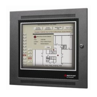
Descriptions Introduction IRST ISION 1.2 F Descriptions IRST ISION 1.2.1 Product Overview uses a graphical user interface (GUI) approach to life safety monitoring for your IRST ISION building. The GUI's display method enables an authorized event responder (e.g. firefighter) to view an event in the context of the building's floor layouts. -
Page 10: Compatibility
Introduction Descriptions IRST ISION Compatibility NOTE: F 1.5 (and above) must be used with gateway versions 3.x and above IRST ISION is compatible with the node types listed in the following table. IRST ISION Table 1.3 F Node Compatibility Table IRST ISION NOTI•FIRE•NET™... -
Page 11: 2: Networking
Descriptions Introduction IRST ISION 1.2.2 Networking The following figure illustrates a possible NOTI•FIRE•NET™ network that includes F IRST ISION Refer to “Make Connections to F ” on page 15 for more information. IRST ISION IRST ISION NFN Gateway PC Ethernet (TCP/IP) NFN Gateway Network NFN Network... -
Page 12: Irst Vision
Introduction Agency Approvals 1.2.3 Ordering Information Please verify part numbers with your sales representative before and when you are ordering. Part Number Description FIRSTVISION-ENC Enclosure FIRSTVISION-LCD Liquid Crystal Display (LCD) 1.3 Agency Approvals has been designed to comply with standards set forth by the following regulatory IRST ISION agencies. -
Page 13: Conventions Used In This Manual
Conventions Used in this Manual Introduction 1.4 Conventions Used in this Manual 1.4.1 Notes, Cautions, and Warnings This manual contains notes, cautions, and warnings to alert the reader as follows: NOTE: Supplemental information for a topic, such as tips and references. CAUTION: Summary in bold Information about procedures that could cause programming errors, runtime errors, or equipment damage. - Page 14 Introduction Related Manuals • ONYX®F ™ Cabinet Installation Instructions PID - 53105 IRST ISION • AMPS-24/E Power Supply Manual - 51907 • NOTI•FIRE•NET™ Manual (Version 4.0 & Higher) - 51584 • NFS-320 Installation/Operation/Programming manuals - 52745/52746/52747 • NFS-640 Installation/Operation/Programming manuals - 51332/51334/51333 •...
-
Page 15: Irst Vision Installation Instructions
Section 2 F Installation Instructions IRST ISION NOTE: You can use this information to install the F enclosure (“Enclosure Installation” IRST ISION on page 12) and to make power supply connections to the enclosure’s control board, or you can refer to the ONYX®F ™... -
Page 16: Enclosure Installation
Installation Instructions Enclosure Installation IRST ISION 2.2 Enclosure Installation Refer to “LCD Installation” on page 14 if the enclosure is already installed. NOTE: You can use this information to install the F enclosure and to make power IRST ISION supply connections to the enclosure’s control board or you can refer to the ONYX®F ™... - Page 17 Enclosure Installation Installation Instructions IRST ISION Step 4. Route the LAN cable into the enclosure through one of the available knockouts. NOTE: The power supplies for F and the gateway should use: IRST ISION - a common ground. - the same earth ground. Figure 2.1 F Dimensions (inches) IRST...
-
Page 18: Lcd Installation
Installation Instructions LCD Installation IRST ISION Power Cable from LCD The F IRST ISION enclosure is factory assembled and wired to install/connect the LCD. +24VDC/3A Enclosure’s Control Board Common GND Enclosure’s Control Board From Power Supply LCD Power Cable Figure 2.2 F Power Wiring Diagram IRST ISION... -
Page 19: Irst Vision
Section 3 Enabling F to Monitor Your IRST ISION Building 3.1 Process Overview The procedures documented in the section should be performed after your building’s life safety monitoring system has been customized to F using the ONYX® F ™ IRST ISION IRST ISION... - Page 20 Enabling F to Monitor Your Building Make Connections to F IRST ISION IRST ISION Figure 3.2 F Standard Keyboard and Mouse Connections IRST ISION WARNING: Connector Damage Possible Do not attempt to close the LCD with the keyboard and mouse connected because their cables will make contact with the enclosure’s wiring tray;...
-
Page 21: Figure 3.4 Example Nfn Gateway Embedded System Connections
Make Connections to F Enabling F to Monitor Your Building IRST ISION IRST ISION IRST ISION Three options: * Direct connection using a crossover Ethernet cable * Connection using 2 standard CAT-5 Ethernet cables and a UL-listed hub * Connection to the customer supplied Ethernet (TCP/IP) Network. -
Page 22: Figure 3.5 Example Nfn Gateway Pc System Connections
Enabling F to Monitor Your Building Make Connections to F IRST ISION IRST ISION IRST ISION Three options: * Direct connection using a crossover Ethernet cable * Connection using 2 standard CAT-5 Ethernet cables and a UL-listed hub * Connection to the customer supplied Ethernet (TCP/IP) Network. -
Page 23: Turn On Power To First Vision
Turn on Power to F Enabling F to Monitor Your Building IRST ISION IRST ISION 3.3 Turn on Power to F IRST ISION Turn-on the power supply connected to F . Refer to “F Installation IRST ISION IRST ISION Instructions” on page 11 for installation information. 3.3.1 What Displays After the Initial Power Up of F IRST ISION... -
Page 24: Screen Saver
Enabling F to Monitor Your Building Turn on Power to F IRST ISION IRST ISION Screen Saver supports Windows Screen Saver settings that extend the display’s life and prevent IRST ISION screen image burn in. Only Windows screen saver application is supported, do NOT use a third- party screen saver application. -
Page 25: Set The First Vision Clock And Time Zone
Set the F Clock and Time Zone Enabling F to Monitor Your Building IRST ISION IRST ISION 3.4 Set the F Clock and Time Zone IRST ISION The F system clock is set at the factory, based on the factory time zone. Follow these IRST ISION steps to configure the clock for your local time zone:... -
Page 26: Establish Communication Between Your Lan And First Vision
Enabling F to Monitor Your Building Establish Communication Between Your LAN and F IRST ISION IRST ISION 3.5 Establish Communication Between Your LAN and IRST ISION NOTE: A factory default IP address setting is set to: 192.168.0.4. If you need to change those settings, then use the following information. -
Page 27: Establish Gateway Communication
Establish Gateway Communication Enabling F to Monitor Your Building IRST ISION Step 6. Select the “Use the following IP address” radio button. The “Obtain an IP address automatically” can NOT be used. Step 7. Type in your IP address information on the Internet Protocol (TCP/IP) Properties window (example only shown, the address is dependent on your network). -
Page 28: How To Add A Gateway Using The Configuration Tool
Enabling F to Monitor Your Building Establish Gateway Communication IRST ISION It is anticipated that the factory settings for a gateway may probably work for your application and it is recommended you use them, if possible, instead of setting up new settings. If you want to change the factory settings use the following information NOTE: Your LAN connection must be established before you add a gateway. -
Page 29: Copy Your Exported Building Design To First Vision
Copy Your Exported Building Design to F Enabling F to Monitor Your Building IRST ISION IRST ISION 3.7 Copy Your Exported Building Design to F IRST ISION This copying task can be accomplished using various methods. The copying method will be contingent on your connection to F . - Page 30 Enabling F to Monitor Your Building Display Your Building Design on F IRST ISION IRST ISION 3.8 Display Your Building Design on F IRST ISION Step 1. Locate the F icon displayed on the Desktop. IRST ISION Step 2. Double click on the icon to load the Site.xml file. NOTE: An application is loading message will display.
-
Page 31: Test Your Building Design On First Vision
Test Your Building Design on F Enabling F to Monitor Your Building IRST ISION IRST ISION 3.9 Test Your Building Design on F IRST ISION It is recommended that you simulate an event that F processes that will test the IRST ISION interaction between your building design and F... - Page 32 Enabling F to Monitor Your Building Touch Screen Calibration IRST ISION ™ Installation and Operation Manual - P/N: 53034:Rev: A2 10/29/07 IRST ISION...
-
Page 33: Section 4 Operating Basics Of First Vision
Section 4 Operating Basics of F IRST ISION Experiment with F to gain a basic familiarity with its operation. This helps you ensure IRST ISION is set up and configured correctly. IRST ISION 4.1 Normal Operation (No Events Being Reported) When F software application is started take note of some of the user interface IRST... - Page 34 Operating Basics of F Normal Operation (No Events Being Reported) IRST ISION Figure 4.1 F Display Example: No Alarms IRST ISION NOTE: Device icons that use a device id’s are displayed on F only when they IRST ISION experience an event type that F processes.
-
Page 35: Section 4 Operating Basics Of F V
Normal Operation (No Events Being Reported) Operating Basics of F IRST ISION With the front door open; touching one of the miscellaneous buttons will display an information window or site plan. 3:41:05 PM Figure 4.3 F Display Example: Building Information IRST ISION ™... - Page 36 Operating Basics of F Normal Operation (No Events Being Reported) IRST ISION With the front door open; touching a place on the floor will open a window that displays an enlarged or zoomed view. 3:41:05 PM Figure 4.4 F Display Example: Zoomed Floor Plan IRST ISION ™...
- Page 37 Normal Operation (No Events Being Reported) Operating Basics of F IRST ISION With the front door open; touching inside the Zoomed Floor Plan window near the left side, right side, top, or bottom changes the point of reference of the zoomed area. Touching near a corner of the window will navigate your zoomed view in a combined direction, like down and right.
-
Page 38: Investigating Gateway Disconnection
Operating Basics of F Investigating Gateway Disconnection IRST ISION With the front door open; touching an icon will display information about the image. Figure 4.6 F Display Example: HAZMAT Information IRST ISION 4.2 Investigating Gateway Disconnection The Gateway Connection Icon in the upper left corner of the user interface indicates whether is connected to your gateway (a red X displayed inside the icon means that IRST ISION... -
Page 39: Operation When A Fire Alarm Is Received
Operation When a Fire Alarm is Received Operating Basics of F IRST ISION 4.3 Operation When a Fire Alarm is Received When F receives a fire alarm from a panel it is monitoring, its front door unlocks and a IRST ISION display change in the floor number button takes place indicating which floor the fire alarm is on. - Page 40 Operating Basics of F Operation When a Fire Alarm is Received IRST ISION With the front door open; touching the display near the device icons being displayed will zoom to the area. 3:41:05 PM Figure 4.8 F Display Example: Alarm Zoomed Floor Plan IRST ISION ™...
-
Page 41: Operation After A Fire Alarm Has Been Cleared
Operation After a Fire Alarm Has Been Cleared Operating Basics of F IRST ISION With the front door open; touching the Event List button will display a listing of the current alarms. 3:41:05 PM Figure 4.9 F Display Example: Event List IRST ISION 4.4 Operation After a Fire Alarm Has Been Cleared... -
Page 42: Accessing The Log File
Operating Basics of F Accessing the Log File IRST ISION 4.5 Accessing the Log File maintains a log of the most recent 1,000 events from attached devices. Each log entry IRST ISION contains an event number, a time and date stamp, information identifying the device involved, and the state of the device during the event. -
Page 43: Section 5 The Development Of First Vision
One of Honeywell’s goals was to design a software application that gave the building manager the flexibility to pull in the best data available from different but existing sources. The resulting... -
Page 44: Expected Firefighter Interaction With The First Vision
The Development of F Expected Firefighter Interaction with the F IRST ISION IRST ISION 5.3 Expected Firefighter Interaction with the F IRST ISION supports tasks that help Firefighters determine whether a fire is occurring. To IRST ISION illustrate how F helps the Firefighter, example emergency situations, "Fire Scene 1"... -
Page 45: Figure 5.2 Fire Scene Scenario Roof Plan Information
Expected Firefighter Interaction with the F The Development of F IRST ISION IRST ISION After verifying the building and seeing fire location, the Commander radios firefighting team. As he calls, he continues observation: seconds – Checks layouts of other floors and the roof (as shown in the example in Figure 5.2) to be sure the fire is contained on only those levels. -
Page 46: Figure 5.4 Fire Scene Scenario Building Information
The Development of F Expected Firefighter Interaction with the F IRST ISION IRST ISION The Commander begins directing the team how to attack the fire: where to enter the building, how to approach the fire area, where to get water, how to vent the fire. seconds The Commander notes that no windows have blown out. -
Page 47: Fire Scene 2
Expected Firefighter Interaction with the F The Development of F IRST ISION IRST ISION Fire Scene 2 In this scenario, the fire is near the front of the building and the main entrance drive, so trucks can be positioned easily. If the fire occurred in a back corner or the far side of the building, the Incident Commander would use the Building Site plan to see safe routes for driving the trucks closer to the fire (as shown in the example in Figure 5.5). -
Page 48: Figure 5.6 Example Hazmat Information
The Development of F Expected Firefighter Interaction with the F IRST ISION IRST ISION If hazardous materials were stored near the fire, the Commander would touch the Hazard icon to see what the materials were and how to handle fire in the area (as shown in the example in Figure 5.6). -
Page 49: Figure 5.7 Example Contact Information
Expected Firefighter Interaction with the F The Development of F IRST ISION IRST ISION If the materials were unfamiliar, the Commander could touch the Contact button to see the on call number for the State Hazardous Material expert (as shown in the example in Figure 5.7). That expert would advise the team of dangers, or come personally to the scene. - Page 50 The Development of F Expected Firefighter Interaction with the F IRST ISION IRST ISION ™ Installation and Operation Manual - P/N: 53034:Rev: A2 10/29/07 IRST ISION...
- Page 51 Index Building Design Copy to Terminal 25 Commissioning 39 Computer Specifications 3 Display Properties power 19 FFD Node Compatibility Table 6 LAN 16 manual conventions 9 manuals related 9 Monitor Power 19 Node Compatibility 6 Specifications 3 Touchscreen, PC 3 Test Building Design 27 Touchscreen Specifications 3...
- Page 52 Index ™ Installation and Operation Manual - P/N: 53034:Rev: A2 10/29/07 IRST ISION...
- Page 53 This warranty is void if the product is altered or repaired by anyone other than Honeywell International Inc. or as expressly authorized by Honeywell International Inc. in writing, or is serviced by anyone other than Honeywell International Inc.
- Page 54 World Headquarters 12 Clintonville Road Northford, CT 06472-1610 USA 203-484-7161 fax 203-484-7118 www.notifier.com...