Table of Contents
Table of Contents

Related Manuals for Honeywell STX


Summary of Contents for Honeywell STX
- Page 1 Models: STX / SMX Programming Guide...
- Page 3 In no event is Honeywell liable to anyone for any direct, special, or consequential damages. The information and specifica- tions in this document are subject to change without notice.
-
Page 4: Table Of Contents
Contents 1 About this Guide .........................4 Supplemental Documentation .....................4 Notice ..........................4 Documentation Feedback ....................4 2 Introduction .......................... 6 Features ..........................6 Standards..........................7 User Control Levels......................7 Level Definition ....................... 7 3 Unpacking ..........................10 4 Fastrack Panel Configuration ..................12 Fastrack Setup ........................12 5 Commissioning ........................16 Commission Zones, Devices and Onboard I/O .......... - Page 5 Level 3 User......................36 Forgot Passcode .........................36 Reset Master User Passcode ................. 38 Firmware Update.........................39 Wipe Event Log ........................41 Error messages ........................42 7 Security Instructions ......................44 Common Security Threats....................44 Tips to Mitigate Security Risk ....................44 Security Threads that Affect Honeywell HGR..............45...
-
Page 7: About This Guide
1. About this Guide This guide is for users trained to program the fire panel to work with connected devices. Supplemental Documentation The table below provides a list of documents for various users of STX / SMX fire panels. Document Name Document Number... - Page 8 About this Guide...
-
Page 9: Introduction
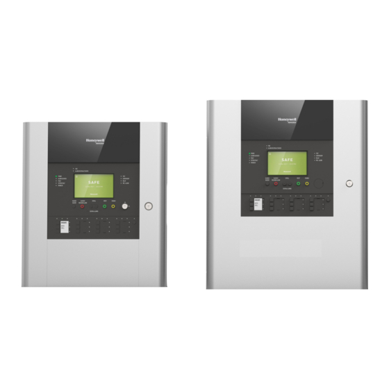
Introduction 2. Introduction The fire alarm control panel is available in two models: STX and SMX. STX Panel SMX Panel The STX model • Comes with a plastic enclosure • Available in 1 loop (98 devices or 198 devices) and 2 loop configurations •... -
Page 10: Standards
• Auto-learning capability • Configuration options: USB storage device, mobile app, and the panel interfaces • 10000 event logs for SMX • 5000 event logs for STX • View pulse width (PW) values • View voltage and analogue values • Monitored input support for supervisory •... - Page 11 Introduction USER LEVEL 3 - All front panel controls are functional. Full system configuration and programming are possible. User Level 3 is reachable by entering a passcode from either Level 1 or Level 2. User Level 3 is for the system installer. Level 3 user can configure passcodes for Level 2 users.
- Page 12 Introduction...
-
Page 13: Unpacking
Unpacking 3. Unpacking The fire alarm control panels are simple to install, program, and commission if you follow the recommended procedures described in this guide. Before installing the panel, ensure that all the equipment is received as per the table given below. - Page 14 Unpacking...
-
Page 15: Fastrack Panel Configuration
Fastrack Panel Configuration 4. Fastrack Panel Configuration The fire alarm control panels are provided with a built-in Fastrack configuration utility that is simple to use. The Fastrack process allows the basic configuration parameters to be programmed using a simple, step-by-step approach. The Fastrack process has the following five simple steps: 1. - Page 16 Fastrack Panel Configuration The following screen appears, tap NEXT. Figure 4.2 Language screen NOTE: The only, default language is English. 2. The following screen appears with the lists of peripherals that are connected to the panel and tap NEXT. Figure 4.3 Peripherals...
- Page 17 Fastrack Panel Configuration The following Loop Details screen appears. Figure 4.4 Loop Screen NOTE: The loop devices can be configured by using auto-learn, one loop at a time. If the panel has more than one loop of devices the total devices configured for each loop is listed before the auto-learn process can continue to the next loop, thereby, allowing you to go back to the previous step, if desired.
- Page 18 Fastrack Panel Configuration The following screen appears after the system reboot. to access the main menu. Figure 4.6 LCD Active State When the panel is in the normal state, it shows “No events present” message and the panel NOTE: screen goes to sleep mode, (screen would appear in grey), which helps in saving the power consumption.
-
Page 19: Commissioning
1. Tap Commissioning from the Main Menu to configure all the devices and the zones in the panel. Figure 5.1 Main Menu NOTE: For Manage, Maintenance, Event Log, and Quick Settings refer STX / SMX User's Guide. 2. Tap next to Zones, Devices & Onboard I/O. - Page 20 Commissioning 3. Tap ZONES. Figure 5.3 Zones, Devices & Onboard I/O 4. The ZONES screen opens with the list of zones in the panel. You can also view the devices assigned to each zone. 5. Tap ADD ZONES to add a new zone and enter the Zone name. The Zone name must be maximum 20 characters.
- Page 21 Commissioning 6. Tap SAVE to add a New zone in the Zones list. Figure 5.5 Zone Name screen NOTE: The panel comes with a qwerty keyboard, you have an option to use alpha-numeric keys, upper-case or lower-case, space, and backspace. For a detailed information on using a qwerty keyboard, see “QWERTY Keyboard Layout”.
- Page 22 Commissioning 8. Tap next to the selected zone that you want to edit. The following screen will appear with the list of devices connected with that zone. Figure 5.7 Edit Label 9. Tap EDIT LABEL. Edit the label description using QWERTY key board, and click SAVE. Refer Figure 5.5 on page 18.
- Page 23 Commissioning 13. The following image appears with All the connected input devices to the loop. Tap next to the selected device. Figure 5.9 Loop Devices 14. For example, in the following image MCP device is selected 15. Tap ADD LABEL to assign a new label to the device, then enter a new label and tap SAVE.
- Page 24 Commissioning NOTE: Latching, Input Action, and Device Type options are not available for TMP (Temperature Detector), OPT (Optical Smoke Detector) and MLT (Multi Sensor). You can only add or edit labels, and assign new zones. 21. Go back to Zones, Devices & Onboard I/O screen. Refer Figure 5.3 on page 17 22.
- Page 25 Commissioning Figure 5.12 Programmable Zone NOTE: The image above shows the PULSE, COINCIDENCE, and COINCIDENCEx3 menus. These menus are inactive in this release and will be available only in a future release. NOTE: If delay is configured for a zone, then the output will remain OFF till the delay period expires, after the delay is over the output will turn ON.
- Page 26 Commissioning 31. Tap to save the set time. The set delay time is applicable for all the outputs. NOTE: A single fire alarm in the zone will cause the programmable zone to be qualified. CAUTION: THE MAXIMUM DELAY IS 10 MINS (600 SECS). 32.
-
Page 27: Learn
Commissioning 37. Tap next to the Sounder to configure the Programmable Zones. Figure 5.14 Local Outputs 38. Tap EDIT PRG ZONES to edit the programmable zones. For more information on editing a programmable zone, see Figure 5.12 on page 22. NOTE: For Programmable Relay, by default the Switch to Supervisory is in YES mode. -
Page 28: User Management
Commissioning 3. A list of devices in the loop are shown in the Loop 1 Learn Summary screen. The loop devices can be configured, one loop at a time. If the panel has more than one loop of devices, the total devices configured for each loop is to be detected and learned individually. - Page 29 Commissioning 3. Tap ADD USER to add a new user in a sequential order. 4. Tap next to the Usename which you want to delete. 5. Tap icon next to the passcode. Figure 5.18 Level 2 user details NOTE: Username is non editable by default. NOTE: You can delete all the users except the 1st user.Edit Passcode 6.
-
Page 30: Configuration Via Bluetooth
Commissioning Figure 5.19 Edit User Passcode NOTE: Enable Show Passcode option to view the passcode you are entering. Configuration via Bluetooth This feature enables you to configure the panel via Bluetooth. You can send and receive configuration file via Bluetooth between panel and PC tool/Mobile App. 5.4.1 Transferring the Configuration File To transfer the configuration file from the mobile to the panel, follow the steps given below: 1. - Page 31 Commissioning 5. The Bluetooth icon is active in the panel and is paired with the mobile device. 6. Tap SEND CONFIGURATION TO PANEL to send the configuration file from the mobile device to the panel. 7. The reading of the configuration file begins. Figure 5.21 Read Configuration File 8.
-
Page 32: Sending The Configuration File
Commissioning 5.4.2 Sending the Configuration File To send the configuration from the panel to the mobile, follow the steps below: 1. For inserting the dongle and paring the mobile device, following “steps 1 to 6” from Transferring the Configuration File on page 27. -
Page 33: Error Messages
The selected config file is incompatible Configuration file of a different panel variant is used. For with this panel variant. example, configuration file of an STX panel is used in the SMX panel. Corrective Action: Use the configuration file of the same variant of the same... -
Page 34: Event Log Explorer
Commissioning Table 5.1 USB-Related Error Messages Serial Error Message Details The selected config file has loop The number of loops of the source panel and the target mismatch with this panel variant. panel are different. For example, the number of loops in the configuration file is 2. -
Page 35: Settings
Commissioning Settings In the Settings tab, you can set the panel settings. Figure 5.25 Settings The table lists the default panel configuration settings. Table 6: Default Panel Settings Setting Option Title Default Description Options Site Name Blank 20 character Configure text for Site text Reference Name to be used when the user contacts the service/ maintenance... - Page 36 Commissioning Table 6: Default Panel Settings Setting Option Title Default Description Options Panel Description Blank 20 character Configure text for Pane Description to text be used. Phone Number Blank 20 character Configure phone number of service/ text maintenance provider. Service Date 01 Jan 2000 Date Set service date based on agreed main-...
-
Page 37: Administration
Administration 6. Administration The Admin is the Master user who has user level 4 access rights. The Master User (level 4) updates the firmware and manages level 2 and level 3 users. The Master user has the Administration privileges for the following tabs: •... - Page 38 SAVE IN USB Figure 6.3 Forgot Passcode NOTE: Email the file to the technical support team at [email protected]. NOTE: The technical support team will generate a reset file and will send it back to the administrator. The file is valid only for 20 days from the date the reset code is sent.
-
Page 39: Reset Master User Passcode
Administration 5. Master user passcode screen appears. The panel reads the file and resets the passcode to the default passcode. 6.2.1 Reset Master User Passcode 6. In the Main screen, tap Administration. 7. Enter the default passcode. 8. Tap User Management tab. 9. -
Page 40: Firmware Update
Administration Figure 6.5 Edit Passcode 14. A message confirming passcode reset message appears. Tap OK. Firmware Update To update the firmware version, you need the user level 4 access. 1. In the Administration screen, tap tab. The Firmware update screen FIRMWARE UPDATE displays the current firmware version details. - Page 41 Administration Figure 6.7 Select Firmware File 5. Select the correct version file and tap . The Firmware Upgrade screen UPDATE FIRMWARE appears. 6. Tap to upgrade the firmware version. Figure 6.8 Firmware Upgrade 7. The panel reboots after the firmware update is complete.
-
Page 42: Wipe Event Log
Administration Figure 6.9 Firmware Update - Complete NOTE: The panel will not be functional during the Firmware upgrade process. Make sure not to remove the USB until the upgrade is completed. Wipe Event Log The Master user can wipe the events at Level 2. To wipe the events, tap WIPE. The following image shows the screen: NOTE: Before you clear the events take a back up using USB storage device if required. -
Page 43: Error Messages
Administration Error messages The following are the list of Firmware error message. Table 6.1 Error Messages THEN You select a lower version of the “Firmware Downgrade” message is displayed Firmware You select a higher version of the “Firmware update” message is displayed Firmware You select the same version of the “Firmware Repair”... - Page 44 Administration...
-
Page 45: Security Instructions
This section lists the few security guidelines and tips that you must follow for the Honeywell MorleyIAS Fire Panels. NOTE: These are the tips that Honeywell recommends, but is not limited to. If you find any security vulnerability, report it to [email protected]. -
Page 46: Security Threads That Affect Honeywell Hgr
Security Instructions Security Threads that Affect Honeywell HGR Some of the common security threats that may affect the Honeywell HGR thick client application. 1. We strongly recommend installing the Honeywell SmartConfig PC tool to an isolated Windows PC system. 2. No services or ports (except those that are required for internal maintenance purposes) are allowed on the PC. - Page 47 Security Instructions...
- Page 49 Honeywell Building Technologies ASEAN Level 25, UOA Corp Tower B, Avenue 10 The Vertical, Bangsar South City 59200, Kuala Lumpur, Malaysia Email: [email protected] www.honeywell.com Honeywell Building Technologies India Unitech Trade Centre, 5th Floor Sector – 43, Block C, Sushant Lok Phase – 1 Gurgaon –...