Table of Contents
Quick Links
www.acornfiresecurity.com
Installation instructions
based Fire detection and alarm system
Fau lt
Hea lth y
Power Fault
Vigi lon Fire Syst
GENT 2015
System Fault
Desi gned to EN54
Delay
Test
Prev ious
Disable ment
www.acornfiresecurity.com
Fire
15:4 5
Verify
Sounde r
em
Fire Routing O/P
Active
Pt 2 & 4
Fault/D is
Power
Next
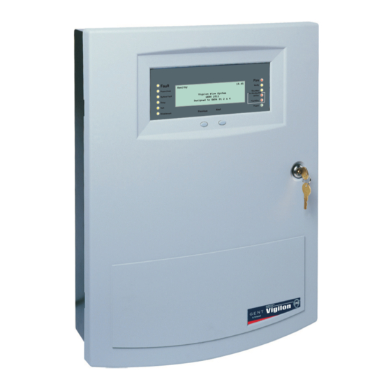
Vigilon panel
Table of Contents

Related Manuals for Honeywell Gent Vigilon


Summary of Contents for Honeywell Gent Vigilon
- Page 1 www.acornfiresecurity.com Installation instructions Vigilon panel based Fire detection and alarm system Fire 15:4 5 Fau lt Verify Hea lth y Sounde r Power Fault Vigi lon Fire Syst Fire Routing O/P Active GENT 2015 System Fault Pt 2 & 4 Desi gned to EN54 Fault/D is Delay...
-
Page 2: Table Of Contents
www.acornfiresecurity.com Contents Batteries and Battery Box Contents Power supply Notes Panel installation Installation Mounting & cable entry points Second fi x Semi-Flush fi xing the control panel Fixture and fi ttings Battery box for VIG1-72 panel As fi tted drawings 19 inch Rack mounting frames Cable type and routing Wiring the battery box... - Page 3 www.acornfiresecurity.com Vigilon fire system Preface Abbreviations This is the forth issue of the Installation Alternating current instructions for the Vigilon 4-6 loop panel Direct current having the 2Km loop cards. It covers the approval of 60hz mains frequency, battery End of line charge current data and fi...
-
Page 4: Notes
www.acornfiresecurity.com Installation Notes As fi tted drawings The power-up of the control panel The installer should acquire site specifi c information from the interested parties, and commissioning of the system is for details on the location of products done by the Servicing organisation. for installation. -
Page 5: Earth Continuity
www.acornfiresecurity.com Vigilon fire system Earth continuity Local Manual Call Point All earth connection points should To comply with the requirements of be clean to provide a good electrical EN54-2 : 1997 a conventional manual call conductivity path. To maintain the earth point must be installed near the Control continuity: all earth leads and fi... -
Page 6: En54 Information
www.acornfiresecurity.com Local Manual Call Point EN54 information Optional functions with requirements of European standard The Control panel complies with the requirements of EN54-2 : 1997. In addition to the basic requirements of the standard the panel conforms to the following optional clauses: Clause Description... -
Page 7: System Wiring
www.acornfiresecurity.com Vigilon fire system System wiring If instructed, the installer may need to terminate as well as connect the cables to the appropriate terminal blocks. Cable separation Where the outgoing and return cables of a loop circuit covers more than the equivalent of one zone they must not run together, for example, either close to the Control Panel or in a service duct. -
Page 8: Cables
www.acornfiresecurity.com Requirements of cables Cables Mains Supply cable The mains supply cable must be a Requirements of cables standard fi re resisting type and should The British Standard meet PH30 classifi cation, such as BS 5839 Part 1 : 2013 Code of standard or enhanced cable. -
Page 9: Loop Cables
www.acornfiresecurity.com Vigilon fire system Enhanced loop cables Loop cables Approved cables for loop wiring There is a maximum limit (EMC Compliant) of 2Km loop cable usage Draka Firetuf FT120 Enhanced - allowed per loop circuit. FTPLUS2EH1.5RD This maximum limit is the (formally Firetuf FT Plus) sum of the cable used on Datwyler Pyrofi... -
Page 10: Network Cables
www.acornfiresecurity.com Network cables Prysmian (formally Pirelli) FP Plus* 1.2Km maximum Panel to Panel or Panel to Network node cable distance The cables marked * utilise 3 Cores each having 1.5mm cross laminated aluminium tape with a section area tinned drain wire for electrostatic screening. - Page 11 www.acornfiresecurity.com Vigilon fire system Belden TR No. 89729 Prysmian (formally Pirelli) (Tefl on jacketed) FP200 Flex* 1.2Km maximum Panel to Panel or 800m maximum Panel to Panel or Panel to Network node cable distance Panel to Network node cable distance 2 twisted pairs 3 Cores, each having 1.5mm cross...
-
Page 12: Loop Circuit Design
www.acornfiresecurity.com Post March 2014 Loop Card Loop circuit design It is important that redundancy is built into the system to accommodate for future expansions and change of area usage in the protected premises. The number of devices on a loop circuit can be limited by the total number of addresses available, the electrical load on the circuit, the maximum cable length and other geographical considerations. -
Page 13: What Are Lumped And Distributed Alarm Device Loads
www.acornfiresecurity.com Vigilon fire system What are Lumped and Distributed alarm device loads? Example of Lumped alarm device load Example of Distributed alarm device load Distributed alarm devices are evenly Where 35% of the alarm devices spaced along the entire length of the loop cable lumped together in 1/4 segment of a loop. -
Page 14: Typical Vigilon System
www.acornfiresecurity.com Typical Vigilon System Typical Vigilon System The loop allows wiring of addressable devices like fi re sensors, alarm sounders, call points, interface units, mimic and repeat panels, a combined maximum of up to 200 devices are allowed per loop circuit, a further limit on a loop circuit is determined by device loading. -
Page 15: Vigilon Panel
www.acornfiresecurity.com Vigilon fire system Vigilon panel Features Analogue addressable fi re detection and alarm control Supports up to four or six loop circuits per panel Fire 15:45 Fault Verify Heal thy Up to 200 addressable devices can be ... -
Page 16: Technical Data
www.acornfiresecurity.com Technical data Technical data Control panel Standard Designed to EN54-2:1997 + A1:2006 (and include optional clauses 7.8, 7.9, 7.9.1, 7.10, 7.10.1, 7.11, 7.12.3, 8.3, 9.5 and 10) Approval LPCB approved Panel dimensions in mm height 543 x width 406 x depth 172 with outer door Panel weight VIG1-24... - Page 17 www.acornfiresecurity.com Vigilon fire system Plug in Card slots MCC / LCC -P1 Master Control card - supplied IOC / N/W -P2 Input Output card / Network card Loop 1 - P3 Loop card - supplied Loop 2 - P4 Loop card option Loop 3 - P5 Loop card option Loop 4 - P6...
-
Page 18: Batteries And Battery Box
www.acornfiresecurity.com Technical data Access level 2b Customer (Customer PIN) Access as level 2a plus access to complete level 2 menu commands. Access level 3 Engineering (Engineers PIN) Access as level 2b plus access to all level 3 menu commands. Menus [Control], [Setup], [Information] and [Test Engineering] menus. -
Page 19: Power Supply
www.acornfiresecurity.com Vigilon fire system Power supply Standard Designed to EN54-4 : 1997 + A1:2002 and A2:2006 Mains supply voltage and 230V -15% +10% 50Hz/60Hz fuses protected by: FS3 T3.15AH250V Ceramic (20 x 5 mm) on PSU Input current - 1.4A Nominal supply voltage for 24V +1V, -4V master alarm circuits... -
Page 20: Panel Installation
www.acornfiresecurity.com Panel installation Panel installation A VIG1-24 and VIG1-72 panels include the following parts: Back box assembly with PSU to power the Control panel Inner door for Control panel Moulded outer door Loop Card (1- loop card supplied), can accommodate up to 4 maximum in a ... -
Page 21: Mounting & Cable Entry Points
www.acornfiresecurity.com Vigilon fire system Mounting & cable entry points These instructions cover installation of the panel and battery box. The cards and batteries are installed during the commissioning of the system by the servicing organisation. The control panel can be surface or fl ush mounted. The only time it should not be fl ush mounted is when the battery box is close fi... -
Page 22: Semi-Flush Fixing The Control Panel
www.acornfiresecurity.com Semi-Flush fixing the control panel The fi xings must support a fully assembled Control panel and Battery box. The VIG1-24 panel with batteries weigh 22.2Kg and the VIG1-72 panel weigh 10.2Kg. The batteries for a VIG1-72 panel are mounted in an external battery box weighing either 31.2Kg (4 batteries) or 55.2Kg (8 batteries). -
Page 23: Battery Box For Vig1-72 Panel
www.acornfiresecurity.com Vigilon fire system Battery box for VIG1-72 panel The connecting battery cables from the control panel to the battery box can be either 1.5mm or 2.5mm The battery box can be mounted beneath the control panel or in a remote location. The battery box can be up to 10m cable distance away using 1.5mm cable or 15m cable distance using 2.5mm... -
Page 24: Wiring The Battery Box
www.acornfiresecurity.com Wiring the battery box Wiring the battery box Wiring options Cable distance 1.5mm² - 10m maximum 2.5mm² - 15m maximum Control panel Battery box Control panel in a remote location Here the battery box is shown mounted beneath the control panel Where the wiring is terminated Panel Battery... -
Page 25: Cable Termination On Enclosure
www.acornfiresecurity.com Vigilon fire system Cable termination on enclosure MICC Softskin (Fire Tuf) CABLE TERMINATION CABLE TERMINATION MICC CABLE MICC CABLE EARTH DRAIN Softskin Cable GLAND GLAND WIRE Should not ZINC PLATED ZINC PLATED be more than GLAND GLAND LOCK WASHER LOCK WASHER 50mm long and must be... -
Page 26: Mains Supply
www.acornfiresecurity.com Mains supply Mains supply Ensure that the mains supply cable enters the panel through a dedicated cable entry point. These fi re alarm system products are NOT designed to be powered from IT Power systems. All mains powered equipment must be earthed. The mains supply to the control panel must be via an unswitched 5A fused spur unit. -
Page 27: Terminals For External Circuits
www.acornfiresecurity.com Vigilon fire system Terminals for external circuits The Terminal card holds all the terminals for the connection of external circuits. The exceptions are: terminals for CARDS in slots P7 and P8, these are located on the Backplane terminals for mains supply, these are located on PSU ... -
Page 28: Device Loop Circuits
www.acornfiresecurity.com Device loop circuits Device loop circuits Each loop circuit can each accept the connection of addressable devices / outstations, up to 200 maximum per circuit. To maintain earth continuity on a loop, the loop cable screen must be continued through each system device, whether the earth is connected to a device or not. -
Page 29: Master Alarm Circuits
www.acornfiresecurity.com Vigilon fire system Master alarm circuits The two master alarm circuits accept the connection of conventional alarm sounders, such as the conventional S-Cubed products. 22K Ohms - End-of-line resistor fitted in the last alarm sounder Conventional alarm sounders MA1+ MA1- MA2+ MA2- MASTER ALARMS MA1 - FS2 1A Terminal card... -
Page 30: Auxiliary Relay Circuits
www.acornfiresecurity.com Auxiliary relay circuits Auxiliary relay circuits The control panel operates the auxiliary contacts when the confi gured event is received from the system. The auxiliary relays 1 and 2 contacts can be used to control external equipment, such as an automatic dialer that makes the call for fi re fi ghting action. The relays can be individually re-confi... -
Page 31: Rs232 / Rs485 Communication
www.acornfiresecurity.com Vigilon fire system RS232 / RS485 Communication The control panel offers RS232 and RS485 communication via the IO card. A standard IO card (not supplied) must be inserted in slot P2 of the backplane of the panel, which facilitate RS232 and RS485 communication via terminal block P4 on Terminal card. -
Page 32: Connecting A Remote Printer
www.acornfiresecurity.com Connecting a Remote printer Connecting a Remote printer An IO card (not supplied) must be inserted in slot 2 of the backplane of the panel, which will facilitate remote printer functionality. When a remote printer is connected to a standalone Vigilon control panel, it will print local system events. -
Page 33: Network Of Systems
www.acornfiresecurity.com Vigilon fire system Network of systems It is possible to network together up to 31 Vigilon EN54 Vigilon Control panels and Network Nodes, each fi tted with a network card for network connections. The Network card permits communication between other control panels and network nodes. The cable distance between panels and nodes can be up to 1.2Km maximum when copper network card is fi... -
Page 34: Network Connections
www.acornfiresecurity.com Network connections Network connections N/C - No connection Cable screen 0V1 +VE1 -VE1 0V2 N/C +VE2 -VE2 N/C 0V1 +VE1 -VE1 0V2 N/C +VE2 -VE2 N/C Connections for Connections for Network card in Network card in Socket P8 (Card 6) Socket P8 (Card 6) (post 08-2006) BACKPLANE... -
Page 35: Fibre Network Connections
www.acornfiresecurity.com Vigilon fire system Fibre network connections Side 2 Side 2 Side 1 Side 1 (End 2) (End 2) (End 1) (End 1) BACKPLANE BACKPLANE Control Panel Control Panel Links P2 and P3 are booster links. Normally the links are not fitted, however for distance exceeding 750m the links must be fitted. -
Page 36: Domain Bridge Across Networks
www.acornfiresecurity.com Domain Bridge across Networks Domain Bridge across Networks It is possible to connect two or more Vigilon networks together by means of domain bridge. To domain bridge two or more networks a Domain bridge IO card must be installed in the bridging node / panel. There are various methods of domain bridging depending on the distances between node / panel. -
Page 37: Fibre Optic Domain Bridge Using Fo Network Dom Card
www.acornfiresecurity.com Vigilon fire system Fibre Optic Domain bridge using FO Network DOM card DOMAIN Fire Fire 15:45 15:45 Fault Verify Fault Verify Healthy Healthy Power Fault Sounder Power Fault Sounder Vigilon Fire System Vigilon Fire System System Fault GENT 2015 Pt 2 &... -
Page 38: Domain Bridge Using Nport Module
www.acornfiresecurity.com Domain bridge using NPORT module Domain bridge using NPORT module The customer is to supply the IP addresses. Domain 2 Domain 1 Dedicated Computer Fire Fire 15:45 15:45 Fault Verify Fault Verify Healthy Healthy Sounder Sounder Power Fault Power Fault Vigilon Fire System network Vigilon Fire System... -
Page 39: Modem Domain Bridge
www.acornfiresecurity.com Vigilon fire system Modem Domain bridge Domain 1 Domain 2 DOMAIN Fire BRIDGE Fault 15:45 Verify Healthy Power Fault Sounder Vigilon Fire System Fire Routing O/P System Fault GENT 2015 Designed to EN54 Pt 2 & 4 Delay Power Test Next Previous... -
Page 40: S-Quad Sensors
www.acornfiresecurity.com On completion of wiring installation S-Quad Sensors This following is short information on the S-Quad product range. The S-Quad product integrates dual angle smoke, heat and carbon monoxide gas detection with electronic sounder, speech and LED fl asher in one assembly. Full information on S-Quad Devices can be downloaded from www.gentexpert.co.uk by registered users. -
Page 41: Siting
www.acornfiresecurity.com Vigilon fire system Siting A S-Quad device plugs into a dedicated Base that is installed in the protected premises. The Bases should be sited in locations as defi ned by the project plans and by BS 5839 : Part 1 : 2013. Do’s and Don’t Follow recommendations detailed in section 22 that relate to automatic fi... -
Page 42: Metal Back Box
www.acornfiresecurity.com Metal back box Metal back box A metal back box must be used for surface or semi-fl ush mounting. The earth continuity must be maintained throughout the whole loop. The earth must be securely connected to the back box. Standard Metal Box Cable gland Loop cable... -
Page 43: Programmable Input/Output
www.acornfiresecurity.com Vigilon fire system Programmable input/output All S-Quad devices can be confi gured as either monitored input or unmonitored output. The factory setting of the programmable input / output is unmonitored output, to drive an external repeat LED without a series resistor. There is a maximum cable length limit of 15 metres from the S-Quad base to the external I/O Unit. -
Page 44: Tools For S-Quad
www.acornfiresecurity.com Tools for S-Quad Tools for S-Quad To fi t a dust cover Place the dust cover onto the tool inside An extractor tool allows removal and the cradle. Offer the cover to the S-Quad, fi tting of the S-Quad device head into the locate and push to fi... -
Page 45: Vigilon Panel Parts
www.acornfiresecurity.com Vigilon fire system Vigilon panel parts This section lists parts associated with the Vigilon panel based system. For further information on the availability of the parts contact your supplier. Control Panel VIG1-24 EN54 Control panel with printer (24 hour standby) c/w 1 loop card and 2 x 12V 21Ah batteries VIG1-24-NP EN54 Control panel without printer (24 hour standby) - Page 46 www.acornfiresecurity.com S-Quad - Sensors Network Node VIG-NODE-24 Network node Domain Bridge products VIG-NPORT-100 NPORT IP Domain module 100m (single unit) VIG-DOM-MODEM Modem pair Printer PRINTER-HAND Handheld serial thermal printer PRINTER-H-PAPER Thermal paper for handheld printer Manuals 4188-1025 EN54 Vigilon 4/6 loop panel based system Operating instructions 4188-749 Log book...
- Page 47 www.acornfiresecurity.com Vigilon fire system Notes www.acornfiresecurity.com...