
Related Manuals for Honeywell NFS Supra


Summary of Contents for Honeywell NFS Supra
- Page 1 NFS Supra / VSN-2Plus / ESS-2Plus Conventional Fire Alarm Control Panel Installation and Operating Manual HLSI-MN-025-I v.04 February 2015...
- Page 2 NFS Supra Note: This manual is valid for the following control panel models: NFS-Supra o NFS4-Supra o NFS8-Supra o NFS12-Supra VSN-2Plus o VSN4-2Plus o VSN8-2Plus o VSN12-2Plus ESS-2Plus o ESS4-2Plus o ESS8-2Plus o ESS12-2Plus To make comprehension easier, when reference is made to these control panels, only the NFS-Supra model name is used, however, the information is valid for any of the models indicated above.
-
Page 3: Table Of Contents
NFS Supra Contents 4.2.2 Ferrite Sleeves (Optional)..............23 4.3 Comissioning ..................24 1 Introduction ....................4 4.3.2 Mains Power ..................24 1.1 CE Marking ................... 4 4.3.3 Batteries.................... 25 1.2 System design and Planing ..............4 4.4 Base PCB Wiring Connections ............26 1.3 Personnel ..................... -
Page 4: Introduction
The design drawings should clearly show the positions of all the control panel and field devices. NFS Supra control panels are manufactured in compliance with national and local standards and meet the requirements of UNE-EN 12094-1:2004, UNE-EN 54- 2 and UNE-EN 54-4/A2:2006. -
Page 5: General
Commissioning: To install and configure the NFS Supra control panel, carefully follow the steps in this manual. It is recommended by manufacturer to check the wiring lines before making any connection to the panel or field devices. -
Page 6: En54 Functions
NFS Supra Introduction 1.6 EN54 Functions Commissioning and Configuration. Read carefully the commissioning and configuration procedures of this manual. It is recommended by manufacturer to check the wiring lines before making any connection to the panel or equipment. Do not carry out any configuration functions without fully understanding of their operation. -
Page 7: Use And Operation
(disable/test/enable zone) and 6 function push-button. Alarm zones NFS Supra control panels have 4, 8 and 12 detection zones. Up to 32 sensors (System Sensor Series 800 / ECO1000) and/or manual call points may be connected to each zone The control panel differentiates between an alarm from a sensor and from a call point. -
Page 8: Www.honeywelllifesafety.es
NFS Supra Operation Outputs (Sounders and Relays) The NFS Supra control panel have two sounder outputs, which can be activated by specific zones. Any zone alarm will activate all sounders, by default. EN54-14 A6.2.2.1: The effect of a fault should... - Page 9 NFS Supra Operation Auxiliary 24 Vdc output The control panel has two 24V power supplies for the connection of external low consumption devices (1A max. between both). One of the non-resettable and the other is resettable (power supply is interrupted for a few seconds when the system is reset).
-
Page 10: Keypad And Led Indicators
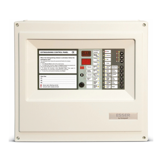
The front panel is divided into three areas: General Status Indicators, Indicators and zone push-buttons and control keypad. 2.1.1 Buzzer NFS Supra control panel has an internal buzzer to warn about events, as follows: -Buzzer steady: Alarm registered in a zone or Evacuation activated. -Intermittent Buzzer*1: System fault. -
Page 11: Led Status Indicators
NFS Supra Operation 2.1.2 LED Status Indicators The front panel Leds are divided into two groups: General System Status Indicators, zone status indicators. control panel has 10 system leds and 2 more leds for each zone. Additionally, the control keys have their own led, to indicate the state of each key, such as Mute Buzzer, Silence/Resound, Evacuate or Delay On/Off. -
Page 12: Www.honeywelllifesafety.es
NFS Supra Operation Disablement (yellow): This led indicates that any zone or sounder output circuits are disabled. If there are Sounder delays, the Disablement led will be lit together with the Sounders delayed led (EN54/2). However, from Access level 3 (programmer), it is possible to program that the sounder delays do not light the Disablement led. -
Page 13: Www.honeywelllifesafety.es
-Led On: System fault. Switch off the 220V power supply and batteries until the Power led is off and connect the power supply again. If the fault continues, contact your supplier. Note: In case that the external relays or communication boards are installed but not communicating with the NFS supra control panel, the system fault led will light. -
Page 14: Www.honeywelllifesafety.es
NFS Supra Operation ZONE INDICATORS The system has a number of alarm detection zones which will correspond, in general, with particular areas of the protected building. In case of incidence in one of these zones, the zone led indicator, indicates their status. In case of Fault, Disablement or Test in one zone, besides the yellow zone LED, the general state LED of the specific event will light. -
Page 15: Function Keys And Zone Keys
NFS Supra Operation 2.1.3 Function keys and zone keys NFS Supra control panel has 5 function push-buttons and a pushbutton for each zone. Zone Keys Function Keys The access to functions and push-button is limited to 2 access levels for users and a third access level only for programmers. -
Page 16: Www.honeywelllifesafety.es
NFS Supra Operation SILENCE/RESOUND: It allows to Silence/Resound and disable sounders. -Silence/Resound: Press the Silence/Resound key to silence the sounders, the Silence/Resound led will be lit. Press this key again to activate sounders again -Disable sounders: When no alarms are activated, press the Silence/Resound key once to disable sounders, the Disablement and Sounders fault/disabled leds will be lit. -
Page 17: Installation Guide
3.2 Pre-installation Check list Antes Before installing the NFS Supra control panel, you must first ensure that the following criteria have been met. Failure to do this may not only result in damage to the equipment, but may also cause problems when commissioning the equipment or adversely affect its performance. -
Page 18: Installation Procedure
Details of each stage are provided in the following sections. 3.4.1 Mounting Plate Installation To prevent distortion, the NFS Supra mounting bracket MUST be installed on the wall as flat as possible, i.e. with a maximum flatness deviation between any two points of 3mm. Where the wall is out of tolerance, use appropriate packing pieces to meet these requirements. -
Page 19: Panel Enclosure Installation
NFS Supra Installation 3.4.2 Panel Enclosure Installation The control panel enclosure is very simple to install providing the mounting plate has been installed correctly as described in Section 3.4.1 Mounting Plate Installation. This procedure assumes that all field cables have been secured on the... -
Page 20: Installing The Batteries
3.4.3 Installing the Batteries The batteries must be located in the dedicated space in the lower part of the NFS Supra enclosure that has space provision for two 7Ah,12V sealed lead batteries. • Orientate the batteries so that the wiring connection terminals of each unit are adjacent to each other (as shown opposite) then offer each in turn to the enclosure. -
Page 21: Cabling Instructions
NFS Supra Installation 4 Installation 4.1 Cabling Instructions All wiring should comply with current wiring regulations or the applicable local wiring regulations. Note also the requirements of EN54-14 (UNE 23007/14) for cabling and interconnection of a fire detection and alarm system. -
Page 22: Cable Terminations
NFS Supra Installation Zones 4.1.1 Cable Terminations This section provides guidance on where to bring cables into the enclosure Leave Blank for ease of termination. Ensure the following requirements are met: 1. The mains supply should be brought into the control panel such that the cable path to PSU is kept as short as possible. -
Page 23: Emc Considerations
NFS Supra Installation 4.2 EMC Considerations Following the above instructions and by using suitable cables EMC problems will be avoided. In particularly difficult EMC environments, or where non-preferred cable is used, it is possible to fit additional ferrite suppressors (sleeves) to cables entering the control panel. -
Page 24: Comissioning
NFS Supra Installation 4.3 Commissioning ELECTRICAL HAZARD! 4.3.1 Preliminary checks WARNING. Risk of electric shock. Before connecting the mains power to the panel, the following must be checked: Before working on mains connections, ensure mains power supply to the panel is disconnected. -
Page 25: Batteries
NFS Supra Installation 4.3.3 Batteries The panel back box can hold up to two 12V, 7Ah batteries. The batteries are not supplied with the panel. Refer to Specification Section for details of recommended batteries Note: The panel can function satisfactorily on batteries only, if required, when mains power is not available. -
Page 26: Base Pcb Wiring Connections
NFS Supra Installation 4.4 Base PCB Wiring Connections The base PCB control panel provides the external cable/wiring connectors for the following functions. To recognize the function of connectors easily, check the associated labels in the PCB Inputs Outputs Z1 Zone 1... -
Page 27: Zone Wirings (1 A 12 Connectors)
However, when installing detectors and call points in the same zone line, please, make sure other local regulations are followed. NFS Supra control panels support an unlimited number of call points per line but some local regulations may limit this number. Please, check the current and applicable regulations before installing alarm devices. - Page 28 EN54-14, no more than 10 MCPs may be connected to one zone. Zener 5V So that the NFS Supra control panels can identify MCP alarms (Alarm LED steady), each normally open (NO) switch contact must be connected in series with a diode Zener of 5.1 V (minimum 1/4W) between 470 Ω...
- Page 29 (EOL) 47µF capacitor or 4K7 Ω resistor must be installed in the output connection of the last detector, between zone positive and negative poles. At each zone of NFS Supra, 32 Honeywell conventional detectors can be connected; however, there may be local regulations more restrictive as for the quantity of detectors.
-
Page 30: Sounder Circuits
Installation EOL Diode 4.4.2 Sounder Circuits The NFS Supra control panel provides two independent, monitored sounder outputs. Sounder circuit wirings must be separated from other cables. There are some local requirements for Notification appliance Circuits. Sounder circuits must be fire resistant according to EN54-14. -
Page 31: Alarm And General Fault Relay
4.4.3 Alarm and General Fault Relay (Standby mode) NFS Supra control panel has two voltage free relays (C, NC, NO): Fault and alarm relay. Common Alarm relay is activated when an alarm is generated at the control panel (the Alarm led also turns on). -
Page 32: Auxiliary 24V Outputs
Installation 4.4.4 Auxiliary 24V Outputs 24Vdc (I 500mA) NFS Supra control panels have two 24 Vdc outputs, supplied from the control panel power supply. 24Vdc (I 500mA) Max. Power from each output is 500mA at 24Vdc, protected by electronic resettable fuse. -
Page 33: Digital Input
NFS Supra Instalación External External contact contact 4.4.5 Digital Input NC C NO C A digital input is provided for external configurable contact in order to control the panel from another system. The following functions are available through a NO or NC external contact (voltage free):... -
Page 34: Configuration
NFS Supra Configuration Configuration 5.1 Introduction It´s possible to configure output and control functions from Access Level 3. Before changing the panel configuration, read this section carefully. Do not make any changes in the configuration unless you have completely understood the operation of the panel. -
Page 35: Default Configuration
NFS Supra Configuration 5.3 Default Configuration NFS Supra is supplied with the following configuration, suitable for most installations. Refer to configuration options for further information: - Digital input: Panel Reset. - Sounders without delays (Delay 1= Delay 2 = 0 sec). -
Page 36: Configuration Options
Reset push button: Change Option (Access Level 3 - Configuration) In NFS Supra control panels, the following functions can be configured: At level 3, the panel leds indicate, the configuration for each option. In order to select one option, the relevant push button must be pressed, following the lighted keys. System leds (Inferior group of leds from 1 to 10) indicate the selected configuration. - Page 37 NFS Supra Configuration Zone type configuration: Select the desired zone by pressing the relevant push-button ZONE=ON (Red or Yellow). The zone led will be lit in red or yellow, depending on the short also section fault/alarm by short circuit. Zone Short Circuit Configuration by pressing the zone key:...
-
Page 38: Delay 1 (Primary Delay - Alarm Acknowledge)
NFS Supra Configuration 5.4.2 Delay 1 (Primary Delay – Alarm acknowledge) Delay 1: Maximum time to press MUTE BUZZER key in order to acknowledge (accept) the alarm start Delay 2. If the MUTE BUZZER key is not pressed, sounders will be activated when delay 1 time is finished. -
Page 39: Delay 2 (Secondary Delay - Alarm Inspection)
NFS Supra Configuración 5.4.3 Delay 2 (Secondary delay – Alarm inspection) Delay 2: Period of time available to check the alarm cause after pressing MUTE BUZZER push- button. After this time, sounders will activate. It is possible to configure a period of time from 0 sec. -
Page 40: Sounders Activation By Zone (Control Matrix)
NFS Supra Configuration 5.4.4 Sounders activation by zone (Control matrix) Sounders activation in zones can be configured independently for detectors and call points: delays operation (Delay 1 and Delay 2) and whether the zone activates or not the sounder. Sounders activation by zones:... -
Page 41: Digital Input
NFS Supra Configuration 5.4.5 Digital Input The digital input of the control panel activates by close contact (by default) or open contact (Configurable option). When the contact is closed/opened between digital input terminals (DIGITAL IN), the following functions are supported by the control panel:... -
Page 42: Disablement Led Indication With Delay
NFS Supra Configuración 5.4.6 Disablement led indication with delay The delay may turn on (EN54-2) the disablement led depending on the configuration. Configuration of disablement led with delays: Select the sounders configuration menu by pressing at the same time the following keys: (KEYPAD ACCESS=ON + DELAY ON/OFF=ON). -
Page 43: Earth Fault Level
NFS Supra Configuration 5.4.8 Earth fault level The system allows to set the earth fault more sensitive, in order to indicate earth leakage fault, with small potential differences between earthed points or when the devices insulation or the cable zones do not have the expected values and thus detect in advance the risk of a earth leakage. -
Page 44: Special Functions (Une-En54 Non-Compliant)
NFS Supra Configuration 5.5 Special Functions (UNE-EN54 non-compliant) The control panel allows special configurations. These configurations do not comply the EN54-2/ and can only be used for special performances and to configure the external relay cards. These options require a special access level. -
Page 45: Check/Change Special Functions Configuration
NFS Supra Configuration 5.5.1 Check/Change special functions configuration: Switch off the control panel (Mains supply and battery disconnection), then connect the (PROG) jumper and connect again the control panel as usual. Special functions leds will be lit, according to the current configuration, as showed below:... - Page 46 NFS Supra Configuration Optional Relay cards configuration The relay cards connected to the Auxiliary Modules bus must be configured to enable them, the correct number of cards must be enabled and configured. If the number of cards enabled/configured is different from the installed, the control panel will indicates System Fault.
-
Page 47: Specifications
6 Specifications General NFS Supra control panels (NFS4/8/12--Supra) have been designed to comply with EN 54 part 2/4:1997 requirements. This panel complies with the European low voltage directive 73/23/EEC (and the amending Directive 93/68/EEC), by the application of the safety standard EN 60950. - Page 48 NFS Supra Specifications Indicators: Cable entry points: Status indicators* : FIRE, Zone alarm and fault, Power, General fault, 15 x 21 mm knockouts (top) and 6 x 21 mm knockouts (back). General disablement, Test, Earth fault, Power supply Dimensions: fault, Sounder fault/disablement.
- Page 49 MCPs. The control panel was designed to function with most brands. It is C, NC, NO contacts max. 30Vdc/ 1A. recommended the installation of Honeywell ECO1000 and Series 800 detectors. Aux. 24V Outputs: 32 ECO1000 and Series 800 detectors and an unlimited number of MCPs can be NFS-Supra has two 24V Aux.
- Page 50 Honeywell Life Safety Iberia C/ Pau Vila, 15-19; 08911 Badalona (Barcelona) Phone: 902 03 05 45 International phone: +34 93 24 24 236 www.honeywelllifesafety.es...