Table of Contents
Quick Links
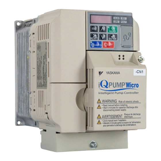
iQpump Micro AC Drive
Compact Intelligent Pump Controller
User Manual
Type: CIMR-PW
Models: 200 V Class, Single-Phase Input: 1 to 5 HP ND
200 V Class, Three-Phase Input: 1.5 to 25 HP ND
400 V Class, Three-Phase Input: 1 to 25 HP ND
To properly use the product, read this manual thoroughly and retain
for easy reference, inspection, and maintenance. Ensure the end user
receives this manual.
MANUAL NO. TOEP YAIQPM 03B
1
Receiving
2
Mechanical Installation
3
Electrical Installation
Start-Up Programming &
4
Operation
5
Parameter Details
6
Troubleshooting
Periodic Inspection &
7
Maintenance
A
Specifications
B
Parameter List
MEMOBUS/Modbus
C
Communications
D
Standards Compliance
Chapters
Table of Contents

Related Manuals for YASKAWA iQpump Micro CIMR-PW Series


Summary of Contents for YASKAWA iQpump Micro CIMR-PW Series
- Page 1 iQpump Micro AC Drive Compact Intelligent Pump Controller User Manual Type: CIMR-PW Models: 200 V Class, Single-Phase Input: 1 to 5 HP ND 200 V Class, Three-Phase Input: 1.5 to 25 HP ND 400 V Class, Three-Phase Input: 1 to 25 HP ND To properly use the product, read this manual thoroughly and retain for easy reference, inspection, and maintenance.
- Page 2 Every precaution has been taken in the preparation of this manual. Yaskawa assumes no responsibility for errors or omissions. Neither is any liability assumed for damages resulting from the use of the information contained in this publication.
- Page 3 3.5 Preparing IP66/NEMA 4X, UL Type 4X Enclosure Drives for Wiring ....47 Select Cable Gland ......................... 47 IP66/NEMA 4X, UL Type 4X Enclosure Front Cover Removal and Installation...... 48 YASKAWA TOEP YAIQPM 03B YASKAWA AC Drive - iQpump Micro User Manual...
- Page 4 4.9 Auto-Tuning ........................101 Stationary Auto-Tuning........................101 Before Auto-Tuning the Drive......................101 Auto-Tuning Interruption and Fault Codes ..................101 Performing Auto-Tuning ........................102 Input Data for Auto-Tuning ......................102 YASKAWA TOEP YAIQPM 03B YASKAWA AC Drive - iQpump Micro User Manual...
- Page 5 H2: Multi-Function Output ....................... 174 H4: Multi-Function Analog Output Terminals .................. 186 H6: Pulse Train Input/Output......................187 5.8 L: Protection Functions ....................189 L1: Motor Protection Functions ....................... 189 YASKAWA TOEP YAIQPM 03B YASKAWA AC Drive - iQpump Micro User Manual...
- Page 6 Operator Programming Error Codes, Causes, and Possible Solutions........... 280 6.6 Copy Function Related Displays ..................283 Tasks, Errors, and Troubleshooting ....................283 6.7 Digital Operator Display Messages .................285 Fault Reset Methods ........................286 YASKAWA TOEP YAIQPM 03B YASKAWA AC Drive - iQpump Micro User Manual...
- Page 7 Dwell Function........................... 324 B.4 C: Tuning..........................325 C1: Acceleration and Deceleration Times ..................325 C2: S-Curve Characteristics......................325 C3: Slip Compensation........................326 C4: Torque Compensation ......................326 C6: Carrier Frequency........................326 YASKAWA TOEP YAIQPM 03B YASKAWA AC Drive - iQpump Micro User Manual...
- Page 8 Q3: Output Current Limit ......................... 366 B.14 S: Special Application.......................367 S6: Protection..........................367 B.15 T: Motor Tuning .........................368 T1: Induction Motor Auto-Tuning..................... 368 B.16 U: Monitors.........................369 U1: Operation Status Monitors ......................369 YASKAWA TOEP YAIQPM 03B YASKAWA AC Drive - iQpump Micro User Manual...
- Page 9 C.11 Enter Command.........................415 Enter Command Types ........................415 C.12 Communication Errors .....................416 MEMOBUS/Modbus Error Codes....................416 Slave Not Responding........................416 C.13 Self-Diagnostics ........................417 D. STANDARDS COMPLIANCE ................419 YASKAWA TOEP YAIQPM 03B YASKAWA AC Drive - iQpump Micro User Manual...
- Page 10 D.1 UL Standards ........................435 UL Standards Compliance ......................435 IP66/NEMA 4X, UL Type 4X Conditions of Acceptability ..............435 Main Circuit Terminal Wiring ......................435 Drive Motor Overload Protection ..................... 440 YASKAWA TOEP YAIQPM 03B YASKAWA AC Drive - iQpump Micro User Manual...
- Page 11 Preface & General Safety This section provides safety messages pertinent to this product that, if not heeded, may result in fatality, personal injury, or equipment damage. Yaskawa is not responsible for the consequences of ignoring these instructions. PREFACE.......................12 GENERAL SAFETY....................13...
- Page 12 Yaskawa must be supplied to the end user with appropriate warnings and instructions as to the safe use and operation of that part. Any warnings provided by Yaskawa must be promptly provided to the end user.
- Page 13 • When ordering a new copy of the manual due to damage or loss, contact your Yaskawa representative or the nearest Yaskawa sales office and provide the manual number shown on the front cover.
- Page 14 Do not attempt to modify or alter the drive in any way not explained in this manual. Failure to comply could result in death or serious injury. Yaskawa is not responsible for any modification of the product made by the user. This product must not be modified. Do not allow unqualified personnel to use equipment.
- Page 15 • to smooth peak current that results from capacitor switching. • when the power supply is above 600 kVA. • when the drive is running from a power supply system with thyristor converters. YASKAWA TOEP YAIQPM 03B YASKAWA AC Drive - iQpump Micro User Manual...
- Page 16 Yaskawa offers protective designs for drives that must be used in areas subjected to oil mist and excessive vibration. Contact Yaskawa or your Yaskawa agent for details.
- Page 17 Yaskawa standard motor. A motor designed specifically for operation with a drive should be used when 100% continuous torque is needed at low speeds.
- Page 18 Make sure that the gear and the lubricant are rated for the desired speed range to avoid gear damage when operating at low speeds or very high speeds. Consult with the manufacturer for applications that require operation outside the rated speed range of the motor or gear box. YASKAWA TOEP YAIQPM 03B YASKAWA AC Drive - iQpump Micro User Manual...
- Page 19 Customers who intend to use the product described in this manual for devices or systems relating to transportation, health care, space aviation, atomic power, electric power, or in underwater applications must first contact their Yaskawa representatives or the nearest Yaskawa sales office.
- Page 20 General Safety This Page Intentionally Blank YASKAWA TOEP YAIQPM 03B YASKAWA AC Drive - iQpump Micro User Manual...
- Page 21 This chapter explains how to inspect the drive upon receipt, and gives an overview of the different enclosure types and components. SECTION SAFETY....................22 MODEL NUMBER AND NAMEPLATE CHECK............23 YASKAWA TOEP YAIQPM 03B YASKAWA AC Drive - iQpump Micro User Manual...
- Page 22 Ensure that the motor is suitable for drive duty and/or the motor service factor is adequate to accommodate the additional heating with the intended operating conditions. YASKAWA TOEP YAIQPM 03B YASKAWA AC Drive - iQpump Micro User Manual...
- Page 23 I – AC drive model <1> E – Serial number Figure 1.1 Nameplate Information Example <1> The address of the head office of Yaskawa Electric Corporation (responsible for product liability) is shown on the nameplate. CIMR - PW 2 0010 Drive...
- Page 24 2.2 (3) 4V0007 3.0 (3) 4V0009 3.7 (5) 4V0011 5.5 (7.5) 11.1 4V0018 7.5 (10) 17.5 4V0023 11 (15) 23.0 4V0031 15 (20) 31.0 4V0038 18.5 (25) 38.0 YASKAWA TOEP YAIQPM 03B YASKAWA AC Drive - iQpump Micro User Manual...
- Page 25 Mechanical Installation This chapter explains how to properly mount and install the drive. SECTION SAFETY....................26 MECHANICAL INSTALLATION................28 YASKAWA TOEP YAIQPM 03B YASKAWA AC Drive - iQpump Micro User Manual...
- Page 26 If the motor is to be operated at a speed higher than the rated speed, consult with the manufacturer. Continuously operating an oil-lubricated motor in the low-speed range may result in burning. YASKAWA TOEP YAIQPM 03B YASKAWA AC Drive - iQpump Micro User Manual...
- Page 27 The power transmission mechanism will make noise and experience problems with service life and durability if the motor is operated at a speed higher than the rated speed. YASKAWA TOEP YAIQPM 03B YASKAWA AC Drive - iQpump Micro User Manual...
- Page 28 Installation Orientation and Spacing NOTICE: Install the drive upright as illustrated in Figure 2.1. Failure to comply may damage the drive due to improper cooling. Figure 2.1 Correct Installation Orientation YASKAWA TOEP YAIQPM 03B YASKAWA AC Drive - iQpump Micro User Manual...
- Page 29 NOTICE: When mounting IP20/NEMA 1, UL Type 1 enclosure drives side by side, the top covers of all drives must be removed as shown Figure 2.4. Figure 2.4 IP20/NEMA 1, UL Type 1 Side-by-Side Mounting in Enclosure YASKAWA TOEP YAIQPM 03B YASKAWA AC Drive - iQpump Micro User Manual...
- Page 30 (4.65) (0.16) (0.79) (0.20) (0.06) (2.32) (0.20) (2.9) <1> The installed 24 V power supply option adds 27 mm (1.06 in.) to the total depth of the drive. YASKAWA TOEP YAIQPM 03B YASKAWA AC Drive - iQpump Micro User Manual...
- Page 31 (4.65) (0.19) (0.79) (0.20) (0.20) (2.56) (0.20) (5.7) <1> The installed 24 V power supply option adds 27 mm (1.06 in.) to the total depth of the drive. YASKAWA TOEP YAIQPM 03B YASKAWA AC Drive - iQpump Micro User Manual...
- Page 32 (0.24) (0.51) (0.51) (0.06) (2.95) (0.20) (12.1) Class <1> The installed 24 V power supply option adds 27 mm (1.06 in.) to the total depth of the drive. YASKAWA TOEP YAIQPM 03B YASKAWA AC Drive - iQpump Micro User Manual...
- Page 33 Dimensions mm (in) Voltage Class Drive Model kg (lb.) BV0006G (17.2) Single-Phase BV0010G 200 V Class (7.36) (10.04) (9.25) (6.22) (9.49) (0.28) (0.10) (5.51) (7.40) (3.94) BV0012G (18.08) YASKAWA TOEP YAIQPM 03B YASKAWA AC Drive - iQpump Micro User Manual...
- Page 34 (0.28) (0.10) (5.51) (7.40) (3.94) 2V0020G (17.86) 4V0005G (16.98) 4V0007G Three-Phase 400 V Class (7.36) (10.04) (9.25) (6.22) (9.49) (0.28) (0.10) (5.51) (7.40) (3.94) (17.42) 4V0009G 4V0011G (17.86) YASKAWA TOEP YAIQPM 03B YASKAWA AC Drive - iQpump Micro User Manual...
- Page 35 (47.84) 21.8 4V0023G Three- (48.06) 205.5 Phase (11.42) (16.54) (12.01) (10.43) (15.75) (0.33) (0.10) (6.22) (8.09) (10.16) (3.54) (3.74) 22.9 400 V Class 4V0031G (50.49) 23.2 4V0038G (51.15) YASKAWA TOEP YAIQPM 03B YASKAWA AC Drive - iQpump Micro User Manual...
- Page 36 Dimensions mm (in) Voltage Drive Model Class kg (lb.) Three- 27.7 Phase 2V0069G (11.42) (18.31) (12.01) (10.43) (17.52) (0.33) (0.10) (6.81) (7.40) (9.76) (5.12) (6.30) (61.07) 200 V Class YASKAWA TOEP YAIQPM 03B YASKAWA AC Drive - iQpump Micro User Manual...
-
Page 37: Table Of Contents
TERMINAL BLOCK CONFIGURATION..............44 PROTECTIVE COVERS..................45 PREPARING IP66/NEMA 4X, UL TYPE 4X ENCLOSURE DRIVES FOR WIRING........................47 MAIN CIRCUIT WIRING..................50 CONTROL CIRCUIT WIRING................55 I/O CONNECTIONS....................59 MAIN FREQUENCY REFERENCE................61 3.10 WIRING CHECKLIST.....................62 YASKAWA TOEP YAIQPM 03B YASKAWA AC Drive - iQpump Micro User Manual... -
Page 38: Section Safety
Always use a thermal overload relay or an over-temperature contact when using a braking resistor. Failure to comply could result in death or serious injury by fire. Power to the drive should be interrupted when the relay is triggered. YASKAWA TOEP YAIQPM 03B YASKAWA AC Drive - iQpump Micro User Manual... - Page 39 Failure to comply could result in damage to the drive and will void warranty. Yaskawa is not responsible for any modification of the product made by the user. This product must not be modified. Route motor leads U/T1, V/T2, and W/T3 separate from other leads to reduce possible interference-related issues.
-
Page 40: Standard Connection Diagram
NOTICE: The minimum load for the multi-function relay output MA-MB-MC is 10 mA. If a circuit requires less than 10 mA (reference value), connect it to a photocoupler output (P1, P2, PC). Improper application of peripheral devices could result in damage to the photocoupler output of the drive. YASKAWA TOEP YAIQPM 03B YASKAWA AC Drive - iQpump Micro User Manual... - Page 41 Safe Disable <7> Input Jumper MEMOBUS/ Modbus comm. RS-485/422 Cable shield ground shielded line control terminal twisted-pair shielded line main circuit terminal Figure 3.1 Drive Standard Connection Diagram YASKAWA TOEP YAIQPM 03B YASKAWA AC Drive - iQpump Micro User Manual...
- Page 42 Stop relay (N.C.) Run command (run on momentary close) Stop command (stop on momentary open) Forward/reverse command (multi-function input: H1-05 = 0) Sequence input common Figure 3.2 3-Wire Sequence YASKAWA TOEP YAIQPM 03B YASKAWA AC Drive - iQpump Micro User Manual...
- Page 43 Terminal Block 24V Power Supply Supply Common Transducer Signal 0-10 Vdc (typical) Functional Earth Cable Shield (Earth (Blue) Ground) Output Internal Circuit Figure 3.4 Transducer 3-Wire Connection Diagram YASKAWA TOEP YAIQPM 03B YASKAWA AC Drive - iQpump Micro User Manual...
-
Page 44: Terminal Block Configuration
2V0010 to 2V0020 4V0002 to 4V0011 Models 2V0030 and 2V0040 4V0018 and 4V0023 Model 2V0069 Models 2V0056 4V0031 and 4V0038 Model BV0018 Figure 3.5 Main Circuit Terminal Block Configurations YASKAWA TOEP YAIQPM 03B YASKAWA AC Drive - iQpump Micro User Manual... -
Page 45: Protective Covers
Figure 3.7 Remove the Terminal Cover on an IP20/NEMA 1, UL Type 1 Drive Loosen two screws attaching the conduit bracket to remove. A –Conduit bracket Figure 3.8 Remove the Conduit Bracket on an IP20/NEMA 1, UL Type 1 Drive YASKAWA TOEP YAIQPM 03B YASKAWA AC Drive - iQpump Micro User Manual... - Page 46 Align the connection tabs on the underside of the top cover with the connection tabs on the drive. Pinch in on the top cover to click the cover into place on the drive. Connection tabs Figure 3.11 Reattaching the Top Cover YASKAWA TOEP YAIQPM 03B YASKAWA AC Drive - iQpump Micro User Manual...
-
Page 47: Preparing Ip66/Nema 4X, Ul Type 4X Enclosure Drives For Wiring
NOTICE: Properly seal the rubber gasket along the outside of the cable gland. Improper seals may allow water or oil into the drive and damage components. Remove the rubber bushings and insert the proper cable glands into the holes and tighten the glands with the locknut. YASKAWA TOEP YAIQPM 03B YASKAWA AC Drive - iQpump Micro User Manual... - Page 48 5.4 to 6.0 (47.8 to 53) 4V0001G to 4V0011G 2.0 to 2.5 (17.7 to 22.1) Three-Phase 400 V Class 4V0018G to 4V0038G 5.4 to 6.0 (47.8 to 53) YASKAWA TOEP YAIQPM 03B YASKAWA AC Drive - iQpump Micro User Manual...
- Page 49 Reattach the front cover of the drive enclosure. Refer to Table 3.2 for tightening torque specifications. Drive Front Cover Screw (4) Front Cover Figure 3.16 Attach Enclosure Cover YASKAWA TOEP YAIQPM 03B YASKAWA AC Drive - iQpump Micro User Manual...
-
Page 50: Main Circuit Wiring
U/T1, V/T2, W/T3 14 to 10 1.2 to 1.5 , 1, 2 BV0010 – 14 to 10 (10.6 to 13.3) B1, B2 – 14 to 10 14 to 10 YASKAWA TOEP YAIQPM 03B YASKAWA AC Drive - iQpump Micro User Manual... - Page 51 2.1 to 2.3 (18.6 to 20.4) , 1, 2 – 10 to 6 2V0040 B1, B2 – 14 to 10 2 to 2.5 10 to 6 (17.7 to 22.1) YASKAWA TOEP YAIQPM 03B YASKAWA AC Drive - iQpump Micro User Manual...
- Page 52 2.1 to 2.3 (18.6 to 20.4) , 1, 2 – 10 to 6 4V0023 B1, B2 – 14 to 10 2 to 2.5 10 to 6 (17.7 to 22.1) YASKAWA TOEP YAIQPM 03B YASKAWA AC Drive - iQpump Micro User Manual...
- Page 53 NOTICE: When using more than one drive, ground multiple drives according to instructions. Improper equipment grounding could result in abnormal operation of drive or equipment. Figure 3.17 Refer to when using multiple drives. Do not loop the ground wire. YASKAWA TOEP YAIQPM 03B YASKAWA AC Drive - iQpump Micro User Manual...
- Page 54 A –Protective Cover to Prevent Miswiring Note: The ground terminal screw on IP20/NEMA 1, UL Type 1 holds the protective cover in place on model 2V0006. YASKAWA TOEP YAIQPM 03B YASKAWA AC Drive - iQpump Micro User Manual...
-
Page 55: Control Circuit Wiring
<1> Do not assign functions to digital relay outputs that involve frequent switching. This may shorten relay performance life. Switching life is estimated at 200,000 times (assumes 1 A, resistive load). YASKAWA TOEP YAIQPM 03B YASKAWA AC Drive - iQpump Micro User Manual... - Page 56 Shield ground Terminal Configuration R+ R- AC AM AC MP HC SC R+ R– S– AC AM AC MP HC SC Figure 3.19 Removable Control Circuit Terminal Block YASKAWA TOEP YAIQPM 03B YASKAWA AC Drive - iQpump Micro User Manual...
- Page 57 Prepare the ends of the control circuit wiring as shown in Figure 3.22. Refer to Wire Size and Torque Specifications on page 57 for details. YASKAWA TOEP YAIQPM 03B YASKAWA AC Drive - iQpump Micro User Manual...
- Page 58 +10.5 Vdc maximum 20 mA 0 to 20 mA (250 Ω) G – Frequency setting potentiometer Figure 3.23 Wiring the Frequency Reference to the Control Circuit Terminals (External Reference) YASKAWA TOEP YAIQPM 03B YASKAWA AC Drive - iQpump Micro User Manual...
-
Page 59: I/O Connections
Forward run/stop Not used SOURCE External fault N.O. Fault reset Multi-setpoint 1 HAND HAND 2 SINK +24V SOURCE Figure 3.25 Sinking Mode: Sequence from NPN Transistor (0 V Common) YASKAWA TOEP YAIQPM 03B YASKAWA AC Drive - iQpump Micro User Manual... - Page 60 External fault N.O. Fault rest External Multi-setpoint 1 power supply HAND +24 V HAND 2 SINK +24V SOURCE Figure 3.26 Source Mode: Sequence from PNP Transistor (+24 V Common) YASKAWA TOEP YAIQPM 03B YASKAWA AC Drive - iQpump Micro User Manual...
-
Page 61: Main Frequency Reference
1: 0 to +10 V, bipolar input (no lower limit) 0 to 3 terminal A2 signal level selection 2: 4 to 20 mA 3: 0 to 20 mA YASKAWA TOEP YAIQPM 03B YASKAWA AC Drive - iQpump Micro User Manual... -
Page 62: Wiring Checklist
Properly separate control circuit wiring and main circuit wiring. – Analog signal line wiring should not exceed 50 m. – Safe Disable Input wiring should not exceed 30 m. – YASKAWA TOEP YAIQPM 03B YASKAWA AC Drive - iQpump Micro User Manual... - Page 63 IQPUMP PRESETS AND FUNCTIONS..............87 AUTO-TUNING.....................101 4.10 NO-LOAD OPERATION TEST RUN..............104 4.11 TEST RUN WITH LOAD CONNECTED...............105 4.12 VERIFYING PARAMETER SETTINGS AND BACKING UP CHANGES....106 4.13 TEST RUN CHECKLIST..................108 YASKAWA TOEP YAIQPM 03B YASKAWA AC Drive - iQpump Micro User Manual...
-
Page 64: Section Safety
Verify that the rated voltage of the drive matches the voltage of the incoming power supply before applying power. Do not use improper combustible materials. Failure to comply could result in death or serious injury by fire. Attach the drive to metal or other noncombustible material. YASKAWA TOEP YAIQPM 03B YASKAWA AC Drive - iQpump Micro User Manual... - Page 65 Failure to comply could result in damage to the drive and will void warranty. Yaskawa is not responsible for any modification of the product made by the user. This product must not be modified. Check all the wiring to ensure that all connections are correct after installing the drive and connecting any other devices.
-
Page 66: Drive Start-Up Preparation
The drive is thoroughly tested at the factory. The start up person should verify that the drive is free of shipping and installation damage. Shipping damage is not covered by the Yaskawa warranty. Claims must be filed with the shipping company as soon as possible for any potential recovery via insurance. - Page 67 Record any other connections to the drive to determine if special programming is required for the following: Multi-function Inputs Multi-function Outputs Multi-function Digital Inputs Multi-function Analog Outputs Network Communications YASKAWA TOEP YAIQPM 03B YASKAWA AC Drive - iQpump Micro User Manual...
-
Page 68: Powering Up The Drive
Data displayed varies by the type of fault. Fault Solutions on page 253 for more information and possible solution. are lit. Main circuit low voltage (ex) Note: Display will vary depending on drive settings. STOP YASKAWA TOEP YAIQPM 03B YASKAWA AC Drive - iQpump Micro User Manual... -
Page 69: Using The Standard Digital Led Operator
Lit while the drive is in HAND mode. Refer to page for details. HAND ALM LED Light REV LED Light Refer to LED Screen Displays on page DRV LED Light FOUT LED Light YASKAWA TOEP YAIQPM 03B YASKAWA AC Drive - iQpump Micro User Manual... - Page 70 AUTO mode, Ready, No run command input. HAND Short blink (15% duty) AUTO AUTO mode, stopped by a Fast- Stop from a Multi-Function Digital Input. HAND Double blink YASKAWA TOEP YAIQPM 03B YASKAWA AC Drive - iQpump Micro User Manual...
- Page 71 RUN Command 6 Hz 0 Hz Frequency AUTO LED Short blink Blink Blink HAND LED Operation Mode AUTO Figure 4.2 LEDs and Drive Operation in AUTO and HAND Modes YASKAWA TOEP YAIQPM 03B YASKAWA AC Drive - iQpump Micro User Manual...
- Page 72 The PID Feedback unit is animated with a P alternating with a rising level. The PID Feedback unit is not shown when the value rises above 4 digits. YASKAWA TOEP YAIQPM 03B YASKAWA AC Drive - iQpump Micro User Manual...
-
Page 73: The Drive And Programming Modes
Press and the drive will confirm the change. The display automatically returns to the screen shown in Step 4. Press the key until back at the initial display. YASKAWA TOEP YAIQPM 03B YASKAWA AC Drive - iQpump Micro User Manual... -
Page 74: Using The Optional Hoa Keypad
Lit while the drive is in HAND mode. Refer to page for details. HAND ALM LED Light Refer to ALARM (ALM) LED Displays on page 76 for details. YASKAWA TOEP YAIQPM 03B YASKAWA AC Drive - iQpump Micro User Manual... - Page 75 (F2) RESET Pressing resets the existing drive fault error. Monitor Pressing switches Monitor mode. Indicates forward motor operation. FWD/REV Indicates reverse motor operation. YASKAWA TOEP YAIQPM 03B YASKAWA AC Drive - iQpump Micro User Manual...
- Page 76 AUTO mode, Ready, No run command input. HAND Short blink (15% duty) AUTO AUTO mode, stopped by a Fast- Stop from a Multi-Function Digital Input. HAND Double blink YASKAWA TOEP YAIQPM 03B YASKAWA AC Drive - iQpump Micro User Manual...
- Page 77 The factory default setting for the drive is 4~20 mA feedback device connected to analog input A2. Real Time Clock Setting Display Note: Setting the Real-Time Clock will clear a “Clock Not Set” alarm. YASKAWA TOEP YAIQPM 03B YASKAWA AC Drive - iQpump Micro User Manual...
- Page 78 After entering the Real-Time Clock data, press the ENTER key to save the changes. The display will indicate “Entry Accepted” and return to the initial display in step 3 and the alarm LED will be OFF. Entry accepted YASKAWA TOEP YAIQPM 03B YASKAWA AC Drive - iQpump Micro User Manual...
- Page 79 Press the ENTER key and the time setting screen will appear. Use the right arrow key to select YYYY/MM/DD HH:MM 0/01/01 00:00 the desired digit, then set the correct date and time using the up and down arrow keys. Second per month + 0 sec YASKAWA TOEP YAIQPM 03B YASKAWA AC Drive - iQpump Micro User Manual...
- Page 80 Setting 2: Reset The Real-Time Clock data is cleared. A Clock Not Set alarm will occur until o4-17 is set to 1 and the Real-Time Clock is set. YASKAWA TOEP YAIQPM 03B YASKAWA AC Drive - iQpump Micro User Manual...
- Page 81 <5> The Frequency Reference appears after the initial display that shows the product name. <6> The information that appears on the display will vary depending on the drive model. YASKAWA TOEP YAIQPM 03B YASKAWA AC Drive - iQpump Micro User Manual...
- Page 82 Select Language Home DATA -PRMSET- Basic Setup 4. Press C1-01= 20.0 sec to select the C parameter group. Accel Time 1 Home DATA YASKAWA TOEP YAIQPM 03B YASKAWA AC Drive - iQpump Micro User Manual...
- Page 83 The following example details where the drive was initialized to Pump Down Mode (A1-03 = 6009) and then three additional parameters were changed including the deceleration time. The example shows how to then change the deceleration time from 14.0 s to 24 seconds. YASKAWA TOEP YAIQPM 03B YASKAWA AC Drive - iQpump Micro User Manual...
- Page 84 If parameters other than C1-02 have been changed, use to scroll until C1-02 “10.0sec” Home appears. - VERIFY - PRG Accel Time 1 C1-01=0014.0sec Press to access the setting value. Left digit flashes. (0.0~6000.0) “10.0sec” Home YASKAWA TOEP YAIQPM 03B YASKAWA AC Drive - iQpump Micro User Manual...
- Page 85 DATA - MODE - Auto Setpoint U5-99= 0.0PSI 10. Press as many times as necessary to return to the initial display. U1-02= 0.00Hz LSEQ U1-91= 0.0PSI LREF <-MONITOR-> YASKAWA TOEP YAIQPM 03B YASKAWA AC Drive - iQpump Micro User Manual...
-
Page 86: Pump Application Presets
E2-04 b1-02 E2-04 P1-03 P1-02 C1-01 d1-01 Q1-01 P1-03 C1-02 P1-06 P1-04 Q1-01 E2-01 P4-10 P1-06 P1-04 E2-04 P5-04 P4-10 P1-06 L5-01 P5-04 P2-02 L5-04 P4-10 P1-06 P5-04 YASKAWA TOEP YAIQPM 03B YASKAWA AC Drive - iQpump Micro User Manual... -
Page 87: Iqpump Presets And Functions
P2-02 (Sleep Level). The controller will monitor the water depth feedback signal and wake up when the water depth rises above the setting in parameter P1-04 (Start/Draw Down Level). Logically, set the Sleep Level YASKAWA TOEP YAIQPM 03B YASKAWA AC Drive - iQpump Micro User Manual... - Page 88 Default: 1 P5-04 HAND Key Function Selection Range: 0, 1 Default: 0.0 Q1-01 PID Controller Setpoint 1 Min.: 0.0 Max.: 6000.0 U1-99 Anti-No-Flow Timer No signal output available YASKAWA TOEP YAIQPM 03B YASKAWA AC Drive - iQpump Micro User Manual...
- Page 89 Default: Depends on o2-04 E2-01 Motor Rated Current Min.: 10% of drive rated current Max.: 200% of drive rated current Default: 2 E2-04 Number of Motor Poles Min.: 2 Max.: 48 YASKAWA TOEP YAIQPM 03B YASKAWA AC Drive - iQpump Micro User Manual...
- Page 90 Low City On-Delay Time Min.: 1 Max.: 1000 Default: 5 s P4-23 Low City Off-Delay Time Min.: 0 Max.: 1000 Default: 0 P4-24 Low City Alarm Text Range: 0 to 2 YASKAWA TOEP YAIQPM 03B YASKAWA AC Drive - iQpump Micro User Manual...
- Page 91 If desired, program a multi-function digital output (H2-oo) to 89 (Output Current Limit) to annunciate the alarm. Related Parameters Parameter Name Setting Values Default: 0 Q3-01 Output Current Limit Select Range: 0, 1 Default: 0.0 A Q3-02 Current Limit Min.: 0.0 Max.: 1000.0 YASKAWA TOEP YAIQPM 03B YASKAWA AC Drive - iQpump Micro User Manual...
- Page 92 Lag Follower Deceleration P9-33 will use the standard deceleration rate when it expires. Min.: 0.0 Time Active Time Setting this parameter to 0.0 disables the function. Max.: 360.0 YASKAWA TOEP YAIQPM 03B YASKAWA AC Drive - iQpump Micro User Manual...
- Page 93 Use shielded communication cable for steps 3 and 4 to connect the drives in a daisy chain manner according to Figure 4.13. Daisy chain the (R+ to S+) terminals between each drive. Daisy chain the (R- to S-) terminals between each drive. YASKAWA TOEP YAIQPM 03B YASKAWA AC Drive - iQpump Micro User Manual...
- Page 94 Drive is not able to communicate to any other U1-02= 0.00Hz U1-02= 0.00Hz drives. U1-91= 62.8PSI U1-91= 62.8PSI <- MONITOR - > Home If a drive displays U9-02 = 0 <->: YASKAWA TOEP YAIQPM 03B YASKAWA AC Drive - iQpump Micro User Manual...
- Page 95 DRV RDY Wait for Net Cmd U5-99= 100.0 Drive is in AUTO Mode and waiting for a run command from the iQpump MEMOBUS U1-02= 0.00Hz network. U1-91= 62.8PSI Home YASKAWA TOEP YAIQPM 03B YASKAWA AC Drive - iQpump Micro User Manual...
- Page 96 Max.: FF Default: 0 P1-01 Pump Mode Range: 0, 3 Default: 0 P9-02 Feedback Source Range: 0 to 3 Default: 4 P9-25 Highest Node Address Range: 2 to 4 YASKAWA TOEP YAIQPM 03B YASKAWA AC Drive - iQpump Micro User Manual...
- Page 97 PSI, a high feedback fault should occur and stop the drive. There are multiple methods to handle the pump cycling problem: • Lower the lag fixed speed (P9-06) YASKAWA TOEP YAIQPM 03B YASKAWA AC Drive - iQpump Micro User Manual...
- Page 98 Jockey Pump Drive B Drive C Node Address H5-01 = 1 H5-01 = 2 H5-01 = 3 Highest Node Address P9-25 = 3 P9-25 = 3 P9-25 = 3 YASKAWA TOEP YAIQPM 03B YASKAWA AC Drive - iQpump Micro User Manual...
- Page 99 U5-99 = 90 PSI Start Level P1-04 = 75 PSI P1-04 = 75 PSI P1-04 = 75 PSI <1> All other multiplexing and alternation parameters are set to default settings. YASKAWA TOEP YAIQPM 03B YASKAWA AC Drive - iQpump Micro User Manual...
- Page 100 20 s P9-20 Allow Network Run P9-21 Run Priority P9-24 Lead Swap at Sleep P9-25 Highest Node Address U5-99 PID Setpoint Command 100 PSI 100 PSI 100 PSI YASKAWA TOEP YAIQPM 03B YASKAWA AC Drive - iQpump Micro User Manual...
-
Page 101: Auto-Tuning
If tuning results are abnormal or the STOP key is pressed before completion, Auto-Tuning will be interrupted and a fault code will be displayed on the digital operator. A – Normal Auto-Tuning Display B – Auto-Tuning Interrupted Figure 4.17 Auto-Tuning Interruption Display (Standard Digital LED Operator) YASKAWA TOEP YAIQPM 03B YASKAWA AC Drive - iQpump Micro User Manual... - Page 102 Refer to Stationary Auto-Tuning on page 101 for details on Stationary Auto-Tuning. Name Setting Range Default T1-01 Auto-Tuning Mode Selection 2 (V/f) 2 (V/f) Setting 2: Stationary Auto-Tuning for Line-to-Line Resistance YASKAWA TOEP YAIQPM 03B YASKAWA AC Drive - iQpump Micro User Manual...
- Page 103 50 and 100% of the drive rating. Enter the current at the motor base speed. Name Setting Range Default 10 to 200% of drive rated Determined by T1-04 Motor Rated Current current o2-04 and C6-01 YASKAWA TOEP YAIQPM 03B YASKAWA AC Drive - iQpump Micro User Manual...
-
Page 104: No-Load Operation Test Run
Example: 40 Hz → 60 Hz. HAND The drive should operate normally. Press to stop the motor. The HAND light is off and the motor coasts to stop. AUTO HAND HAND YASKAWA TOEP YAIQPM 03B YASKAWA AC Drive - iQpump Micro User Manual... -
Page 105: Test Run With Load Connected
• If the application permits running the load in the reverse direction, try changing motor direction and the frequency reference while watching for abnormal motor oscillation or vibration. • Correct any problems that occurs with hunting, oscillation, or other control-related issues. YASKAWA TOEP YAIQPM 03B YASKAWA AC Drive - iQpump Micro User Manual... -
Page 106: Verifying Parameter Settings And Backing Up Changes
A1-05: A1-01, A1-02, A1-03, A1-06 and A2-01 through A2-33. Note: Parameter A1-05 is hidden from view. To display A1-05, access parameter A1-04 and simultaneously depress the key and the key. YASKAWA TOEP YAIQPM 03B YASKAWA AC Drive - iQpump Micro User Manual... - Page 107 DriveWizard iQpump is a PC software tool for parameter management, monitoring, and diagnosis. DriveWizard iQpump can load, store, and copy drive parameter settings. For details, refer to Help in the DriveWizard iQpump software. YASKAWA TOEP YAIQPM 03B YASKAWA AC Drive - iQpump Micro User Manual...
-
Page 108: Test Run Checklist
When current input is used, set H3-09 to “2” (4 to 20 mA) or “3” (0 to 20 mA) and set H3-10 to “0”. – When current input is used, switch the drive built-in DIP switch S1 from the V-side (OFF) to I-side (ON). – YASKAWA TOEP YAIQPM 03B YASKAWA AC Drive - iQpump Micro User Manual... - Page 109 F: OPTION SETTINGS..................161 H: TERMINAL FUNCTIONS.................163 L: PROTECTION FUNCTIONS................189 N: SPECIAL ADJUSTMENTS................213 5.10 O: OPERATOR RELATED SETTINGS..............215 5.11 P: PUMP.......................223 5.12 Q: PID CONTROLLER..................245 5.13 U: MONITOR PARAMETERS................247 YASKAWA TOEP YAIQPM 03B YASKAWA AC Drive - iQpump Micro User Manual...
-
Page 110: A: Initialization
Notes on Parameter Access • If the drive parameters are password protected by A1-04 and A1-05, parameters A1-00 through A1-03, A1-06, and all A2 parameters cannot be modified. YASKAWA TOEP YAIQPM 03B YASKAWA AC Drive - iQpump Micro User Manual... - Page 111 Application Presets are available to facilitate drive setup for commonly used applications. Selecting one of these Application Presets automatically assigns functions to the input and output terminals and sets a predefined group of parameters to values appropriate for the selected application. YASKAWA TOEP YAIQPM 03B YASKAWA AC Drive - iQpump Micro User Manual...
- Page 112 Note: A1-05 is normally hidden, but can be displayed by following the directions listed “05” flashes here. Press the key. to enter the password. Press to save what was entered. The display automatically returns to the display shown in step 5. YASKAWA TOEP YAIQPM 03B YASKAWA AC Drive - iQpump Micro User Manual...
- Page 113 A2-33: User Parameter Automatic Selection A2-33 determines whether or not parameters that have been edited are saved to the User Parameters (A2-17 to A2-32) for quick, easy access. YASKAWA TOEP YAIQPM 03B YASKAWA AC Drive - iQpump Micro User Manual...
- Page 114 16 parameters are saved in order with the most recently edited parameter set to A2-17. User parameters can be accessed using the Setup mode of the digital operator. YASKAWA TOEP YAIQPM 03B YASKAWA AC Drive - iQpump Micro User Manual...
-
Page 115: B: Application
Figure 5.3 or an external 0 to 10 Vdc voltage source like a PLC analog output and set the input level selection for A1 in parameter H3-02 as desired. YASKAWA TOEP YAIQPM 03B YASKAWA AC Drive - iQpump Micro User Manual... - Page 116 • Terminal A1 when the digital input set for multi-speed 1 is open. • Terminal A2 when the digital input set for multi-speed 1 is closed. Figure 5.4 shows a wiring example for main/auxiliary reference switching using digital input S5. YASKAWA TOEP YAIQPM 03B YASKAWA AC Drive - iQpump Micro User Manual...
- Page 117 This setting requires a pulse train signal to terminal RP to provide the frequency reference. Follow the directions below to verify that the pulse signal is working properly. YASKAWA TOEP YAIQPM 03B YASKAWA AC Drive - iQpump Micro User Manual...
- Page 118 Parameter b1-11, Run Delay at Stop (Back Spin Timer), is effective for all stopping methods (b1-03 = 0 to 3), not only Coast to Stop w/ Timer (b1-03 =3). YASKAWA TOEP YAIQPM 03B YASKAWA AC Drive - iQpump Micro User Manual...
- Page 119 DC Injection Braking time is determined by the value set to b2-04 and the output frequency at the time the Run command is removed. It can be calculated by: (b2-04) x 10 x Output frequency DC Injection brake time Max. output frequency (E1-04) YASKAWA TOEP YAIQPM 03B YASKAWA AC Drive - iQpump Micro User Manual...
- Page 120 Parameter Name Setting Range Default b1-04 Reverse Operation Selection 0 or 1 Setting 0: Reverse Operation Enabled Possible to operate the motor in both forward and reverse directions. YASKAWA TOEP YAIQPM 03B YASKAWA AC Drive - iQpump Micro User Manual...
- Page 121 A JVOP-183 HOA Keypad must be plugged into the drive for settings 1 and 2 to function. If the keypad is removed, b1-12 will automatically be set to 0 (disabled). Parameter Name Setting Range Default b1-12 Run Delay Memory Selection 0 to 2 YASKAWA TOEP YAIQPM 03B YASKAWA AC Drive - iQpump Micro User Manual...
- Page 122 Sets the phase order for drive output terminals U/T1, V/T2, and W/T3. Parameter Name Setting Range Default b1-14 Phase Order Selection 0 or 1 Setting 0: Standard Phase Order Setting 1: Switched Phase Order YASKAWA TOEP YAIQPM 03B YASKAWA AC Drive - iQpump Micro User Manual...
- Page 123 If b2-01 < E1-09 (Minimum Frequency), then DC Injection/ Short Circuit Braking begins at the frequency set to E1-09. Name Setting Range Default E1-09 Minimum Output Frequency 0.0 to E1-04 1.5 Hz YASKAWA TOEP YAIQPM 03B YASKAWA AC Drive - iQpump Micro User Manual...
- Page 124 Selected frequency Starts at the detected speed reference Output frequency Output current Several milliseconds Min. Baseblock Time b3 -05 <1> (L2-03) Figure 5.13 Speed Search after Baseblock YASKAWA TOEP YAIQPM 03B YASKAWA AC Drive - iQpump Micro User Manual...
- Page 125 When the output current drops below the level as set in b3-02, the output frequency stops decreasing and normal operation resumes. The following time chart illustrates how Current Detection Speed Search operates after a momentary power loss: YASKAWA TOEP YAIQPM 03B YASKAWA AC Drive - iQpump Micro User Manual...
- Page 126 (Refer to b3-01: Speed Search Selection at Start on page 127). With this setting external Speed Search commands are disregarded. 2. By digital inputs: The following input functions for H1-oo can be used. YASKAWA TOEP YAIQPM 03B YASKAWA AC Drive - iQpump Micro User Manual...
- Page 127 When Speed Search at start is used, b3-05 will serve as the lower limit of the minimum baseblock time (L2-03). YASKAWA TOEP YAIQPM 03B YASKAWA AC Drive - iQpump Micro User Manual...
- Page 128 Sets the time the current must be above the level set in b3-17 before Speed Search is restarted. This function has no influence when Current Detection Speed Search is used (b3-24 = 0) Name Setting Range Default b3-18 Speed Search Restart Detection Time 0.00 to 1.00 s 0.10 s YASKAWA TOEP YAIQPM 03B YASKAWA AC Drive - iQpump Micro User Manual...
- Page 129 The difference between the target and the feedback value (deviation) is fed into the PID controller. The PID controller adjusts the drive output frequency in order to minimize the deviation, providing an accurate control of the system variables. YASKAWA TOEP YAIQPM 03B YASKAWA AC Drive - iQpump Micro User Manual...
- Page 130 Keeps flow at a constant level by feeding back flow data. Flow rate sensor Temperature Thermocoupler, Maintains a constant temperature by controlling a fan with a thermostat. Control Thermistor YASKAWA TOEP YAIQPM 03B YASKAWA AC Drive - iQpump Micro User Manual...
- Page 131 Analog Input A1 Set H3-02 = 16 Analog Input A2 Set H3-10 = 16 Note: A duplicate allocation of the PID differential feedback input will result in an oPE alarm. YASKAWA TOEP YAIQPM 03B YASKAWA AC Drive - iQpump Micro User Manual...
- Page 132 5.2 b: Application PID Block Diagram Figure 5.19 PID Block Diagram YASKAWA TOEP YAIQPM 03B YASKAWA AC Drive - iQpump Micro User Manual...
- Page 133 A positive PID input causes an increase in the PID output (direct acting). Setting 1: Inverse Acting A positive PID input causes a decrease in the PID output (reverse acting). YASKAWA TOEP YAIQPM 03B YASKAWA AC Drive - iQpump Micro User Manual...
- Page 134 Determines whether a negative PID output reverses the drive operation direction or not. When the PID function is used to trim the frequency reference (b5-01 = 3 or 4), this parameter has no effect and the PID output will not be limited (same as YASKAWA TOEP YAIQPM 03B YASKAWA AC Drive - iQpump Micro User Manual...
- Page 135 “PID feedback high” (H2-oo = 3F) will be triggered. Both events trigger an alarm output (H1- oo = 10). The drive will continue operation. When the feedback value leaves the loss detection range, the alarm and outputs are reset. YASKAWA TOEP YAIQPM 03B YASKAWA AC Drive - iQpump Micro User Manual...
- Page 136 It resumes the operation when the PID output or frequency reference is above b5-15 for longer than the time set in b5-16. Name Setting Range Default b5-15 PID Sleep Function Start Level 0.0 to 400.0 Hz 0.0 Hz YASKAWA TOEP YAIQPM 03B YASKAWA AC Drive - iQpump Micro User Manual...
- Page 137 Determines the number of digits for the user-defined display for the PID setpoint (Q1-oo) and PID feedback monitors (U5-01, U5-04). The setting value is equal to the number of decimal places. Name Setting Range Default b5-39 PID System Units Display Digits 0 to 3 YASKAWA TOEP YAIQPM 03B YASKAWA AC Drive - iQpump Micro User Manual...
- Page 138 Name Setting Range Default b6-01 Dwell Reference at Start 0.0 to 400.0 Hz 0.0 Hz b6-02 Dwell Time at Start 0.0 to 10.0 s 0.0 s YASKAWA TOEP YAIQPM 03B YASKAWA AC Drive - iQpump Micro User Manual...
- Page 139 Parameter b6-03 sets the frequency that is kept for the time set in b6-04 during deceleration. Name Setting Range Default b6-03 Dwell Reference at Stop 0.0 to 400.0 Hz 0.0 Hz b6-04 Dwell Time at Stop 0.0 to 10.0 s 0.0 s YASKAWA TOEP YAIQPM 03B YASKAWA AC Drive - iQpump Micro User Manual...
-
Page 140: C: Tuning
Fast-stop input is cleared, and the Run command is cycled. A digital output programmed for “During Fast-stop” (H2-01/02/03 = 4C) will be closed as long as Fast-stop is active. YASKAWA TOEP YAIQPM 03B YASKAWA AC Drive - iQpump Micro User Manual... - Page 141 Figure 5.24 Accel/Decel Rate, Example 1 (C1-14 = 0 Hz, E1-04 = 60 Hz, Frequency Reference = 60 Hz) When C1-14 ≠ 0.0 Hz Operation examples are shown in Figure 5.25 Figure 5.26. YASKAWA TOEP YAIQPM 03B YASKAWA AC Drive - iQpump Micro User Manual...
- Page 142 If a STo fault (Step Out Detection) occurs when starting a PM motor, try increasing the value set to C2-01. YASKAWA TOEP YAIQPM 03B YASKAWA AC Drive - iQpump Micro User Manual...
- Page 143 0 to 10000 ms 2000 ms C3-03: Slip Compensation Limit Sets the upper limit for the slip compensation function as a percentage of the motor rated slip (E2-02). YASKAWA TOEP YAIQPM 03B YASKAWA AC Drive - iQpump Micro User Manual...
- Page 144 Adjust C4-01 so the output current does not exceed the drive rated current. C4-02: Torque Compensation Primary Delay Time 1 Sets the delay time used for applying torque compensation. YASKAWA TOEP YAIQPM 03B YASKAWA AC Drive - iQpump Micro User Manual...
- Page 145 <2> Default setting is 7 (Swing PWM), equivalent to setting 2 kHz. Increasing the carrier frequency is fine, but remember that the drive rated current falls when the carrier frequency is increased. YASKAWA TOEP YAIQPM 03B YASKAWA AC Drive - iQpump Micro User Manual...
- Page 146 1. A carrier frequency error (oPE11) will occur when the carrier frequency proportional gain is greater than 6 while C6-03 is less than C6-04. 2. When C6-05 is set lower than 7, C6-04 is disabled and the carrier frequency will be fixed to the value set in C6-03. YASKAWA TOEP YAIQPM 03B YASKAWA AC Drive - iQpump Micro User Manual...
-
Page 147: D: Reference Settings
Frequency Reference 14 (d1-14) Frequency Reference 15 (d1-15) Frequency Reference 16 (d1-16) <1> − − − − Jog Frequency Reference (d1-17) <1> The Jog frequency overrides the frequency reference being used. YASKAWA TOEP YAIQPM 03B YASKAWA AC Drive - iQpump Micro User Manual... - Page 148 0.0 to 110.0% 0.0% Internal frequency reference d2-01 Frequency Reference Upper Limit Operating range Frequency Reference Lower Limit d2-02 Set frequency reference Figure 5.31 Frequency Reference: Upper and Lower Limits YASKAWA TOEP YAIQPM 03B YASKAWA AC Drive - iQpump Micro User Manual...
- Page 149 0.0 to 400.0 Hz 0.0 Hz d3-04 Jump Frequency Width 0.0 to 20.0 Hz 1.0 Hz Figure 5.32 shows the relationship between the Jump frequency and the output frequency. YASKAWA TOEP YAIQPM 03B YASKAWA AC Drive - iQpump Micro User Manual...
- Page 150 The accel/decel hold input must be enabled the entire time or else the hold value will be cleared. YASKAWA TOEP YAIQPM 03B YASKAWA AC Drive - iQpump Micro User Manual...
- Page 151 5 s after the Up/Down 2 command has been released. When the Run command is turned off or the power is switched off, the drive will use the value saved in d4-06 when it restarts. YASKAWA TOEP YAIQPM 03B YASKAWA AC Drive - iQpump Micro User Manual...
- Page 152 Output frequency Bias value is increased using the accel/decel times as set in d4-04 Bias Up 2 command Figure 5.36 Up/Down 2 Bias when d4-03 = 0.0 Hz YASKAWA TOEP YAIQPM 03B YASKAWA AC Drive - iQpump Micro User Manual...
- Page 153 • If d4-03 = 0 Hz, d4-05 = 1 and the Up/Down 2 commands are both open or both closed • Any changes to the maximum frequency set to E1-04 YASKAWA TOEP YAIQPM 03B YASKAWA AC Drive - iQpump Micro User Manual...
- Page 154 Up/Down reference is active. Change d4-10 to 1 to make the Up/Down function independent of the analog input value. Setting 1: Lower Limit is Determined by Parameter d2-02 Only parameter d2-02 sets the lower frequency reference limit. YASKAWA TOEP YAIQPM 03B YASKAWA AC Drive - iQpump Micro User Manual...
-
Page 155: E: Motor Parameters
This parameter can only be changed when the drive is operating in V/f Control. It allows the user to select the V/f pattern from 15 predefined patterns or to create a custom V/f pattern. Parameter Name Setting Range Default E1-03 V/f Pattern Selection 0 to F YASKAWA TOEP YAIQPM 03B YASKAWA AC Drive - iQpump Micro User Manual... - Page 156 Setting = 4 50 Hz Setting = 5 50 Hz Setting = 6 60 Hz Setting = 7 60 Hz Frequency (Hz) Frequency (Hz) Frequency (Hz) Frequency (Hz) YASKAWA TOEP YAIQPM 03B YASKAWA AC Drive - iQpump Micro User Manual...
- Page 157 50 Hz Setting = A 60 Hz Setting = B 60 Hz 1.5 3 1.5 3 1.3 2.5 1.3 2.5 Frequency (Hz) Frequency (Hz) Frequency (Hz) Frequency (Hz) YASKAWA TOEP YAIQPM 03B YASKAWA AC Drive - iQpump Micro User Manual...
- Page 158 3. To make the V/f pattern a straight line set E1-09 = E1-07. In this case the E1-08 setting is disregarded. 4. E1-03 is unaffected when the drive is initialized using parameter A1-03, but the settings for E1-04 through E1-13 are returned to their default values. YASKAWA TOEP YAIQPM 03B YASKAWA AC Drive - iQpump Micro User Manual...
- Page 159 When using the manufacturer Motor Test Report, calculate E2-05 by the formulas below. • E-type insulation: Multiply 0.92 times the resistance value (Ω) listed on the Test Report at 75 °C YASKAWA TOEP YAIQPM 03B YASKAWA AC Drive - iQpump Micro User Manual...
- Page 160 Tuning completes successfully, the value entered will automatically be saved to E2-11. Parameter Name Setting Range Default Depending on E2-11 Motor Rated Power 0.00 to 650.00 kW o2-04 YASKAWA TOEP YAIQPM 03B YASKAWA AC Drive - iQpump Micro User Manual...
-
Page 161: F: Option Settings
F6-04: bUS Error Detection Time Sets the delay time for bUS error detection. Parameter Name Setting Range Default F6-04 bUS Error Detection Time 0.0 to 5.0 s 2.0 s YASKAWA TOEP YAIQPM 03B YASKAWA AC Drive - iQpump Micro User Manual... - Page 162 NetRef/ComRef Function Selection 0 or 1 Setting 0: Multi-Step Speed Operation Disabled If the NetRef command is selected, multi-step speed input frequency references are disabled. This is the same as Yaskawa F7 drives. Setting 1: Multi-Step Speed Operation Enabled Multi-step speed inputs are active and can override the frequency reference from the communications option even when the NetRef command is selected.
-
Page 163: H: Terminal Functions
2. If the Run command is active at power up and b1-17 = 0 (Run command at power up not accepted), the Run LED will flash to indicate that protective functions are operating. If required by the application, set b1-17 to 1 to automatically issue the Run command upon drive power up. YASKAWA TOEP YAIQPM 03B YASKAWA AC Drive - iQpump Micro User Manual... - Page 164 (provided that the Accel/decel ramp hold input is still closed). Setting B: Drive Overheat Alarm (oH2) Triggers an oH2 alarm when the contact closes. Drive operation is not affected because this is an alarm. YASKAWA TOEP YAIQPM 03B YASKAWA AC Drive - iQpump Micro User Manual...
- Page 165 Up or Down command is set. Figure 5.42 shows an Up/Down function example with a lower frequency reference limit set by d2-02, and the frequency reference hold function both enabled and disabled. YASKAWA TOEP YAIQPM 03B YASKAWA AC Drive - iQpump Micro User Manual...
- Page 166 • To trigger the Fast Stop function with an N.O. switch, set H1-oo = 15. • To trigger the Fast Stop function with an N.C. switch, set H1-oo = 17. Figure 5.44 shows an operation example of Fast Stop. YASKAWA TOEP YAIQPM 03B YASKAWA AC Drive - iQpump Micro User Manual...
- Page 167 EFo where o is the number of the terminal to which the external fault signal is assigned. For example, if an external fault signal is input to terminal S3, “EF3” will be displayed. YASKAWA TOEP YAIQPM 03B YASKAWA AC Drive - iQpump Micro User Manual...
- Page 168 Digital Input Open (H1-0☐ = 2☐) H1-2☐ H1-2☐ EF☐ Delay Time EF☐ Delay Time EF☐ Pump Fault or Alarm Figure 5.46 External Pump Fault and Alarm N.O. Always Detected YASKAWA TOEP YAIQPM 03B YASKAWA AC Drive - iQpump Micro User Manual...
- Page 169 1. This function cannot be used simultaneously with settings 42 and 43. 2. The same functions are assigned to terminals S1 and S2 when the drive is initialized for 2-Wire sequence. YASKAWA TOEP YAIQPM 03B YASKAWA AC Drive - iQpump Micro User Manual...
- Page 170 The drive has a built-in function to self-diagnose serial communications operation. The test involves wiring the send and receive terminals of the RS-422/RS-485 port together. The drive transmits data and then confirms that the communications are received normally. YASKAWA TOEP YAIQPM 03B YASKAWA AC Drive - iQpump Micro User Manual...
- Page 171 • If the frequency reference changes for more than saved. the time set to d4-07 during accel/decel, bias value is held until the output frequency meets the reference (speed agree). YASKAWA TOEP YAIQPM 03B YASKAWA AC Drive - iQpump Micro User Manual...
- Page 172 Closed: Thermostat fault not active. Open: Drive will trip on “VLTS - Volute-TStat Flt”. Note: Assigning both 88 and 89 to input terminals will trigger a VLTS-Volute-TStat Flt. YASKAWA TOEP YAIQPM 03B YASKAWA AC Drive - iQpump Micro User Manual...
- Page 173 Setting AF: Emergency Override Forward Run Enables Emergency Override Forward Run (Enabled when S6-01 = 1). Setting B0: Emergency Override Reverse Run Enables Emergency Override Reverse Run (Enabled when S6-01 = 1). YASKAWA TOEP YAIQPM 03B YASKAWA AC Drive - iQpump Micro User Manual...
- Page 174 Output frequency or motor speed does not match the frequency reference while the drive is running. Closed Output frequency or motor speed is within the range of frequency reference ±L4-02. Note: Detection works in forward and reverse. YASKAWA TOEP YAIQPM 03B YASKAWA AC Drive - iQpump Micro User Manual...
- Page 175 Output frequency or motor speed is below L4-01 or has not exceeded L4-01 + L4-02. Note: Frequency detection works in forward and reverse. The value of L4-01 is used as the detection level for both directions. YASKAWA TOEP YAIQPM 03B YASKAWA AC Drive - iQpump Micro User Manual...
- Page 176 The output closes to indicate that the drive is in a baseblock state. While in baseblock, output transistors do not switch and no main circuit voltage is output. YASKAWA TOEP YAIQPM 03B YASKAWA AC Drive - iQpump Micro User Manual...
- Page 177 The output closes when there is an attempt to reset a fault situation from the control circuit terminals, via serial communications, or using a communications option card. Setting 12: Timer Output This setting configures a digital output terminal as the output for the timer function. YASKAWA TOEP YAIQPM 03B YASKAWA AC Drive - iQpump Micro User Manual...
- Page 178 Status Description Open Output frequency or motor speed exceeded L4-03 plus L4-04. Closed Output frequency or motor speed is below L4-03 or has not exceeded L4-03 plus L4-04. YASKAWA TOEP YAIQPM 03B YASKAWA AC Drive - iQpump Micro User Manual...
- Page 179 Motor is being driven in the forward direction or stopped. Closed Motor is being driven in reverse. Output frequency FWD Run command REV Run command During Reverse time Figure 5.61 Reverse Direction Output Example Time Chart YASKAWA TOEP YAIQPM 03B YASKAWA AC Drive - iQpump Micro User Manual...
- Page 180 Outputs a pulse to indicate the watt hours. Setting 3C: LOCAL/REMOTE Status The output terminal closes while the drive is set for LOCAL and opens when in REMOTE. YASKAWA TOEP YAIQPM 03B YASKAWA AC Drive - iQpump Micro User Manual...
- Page 181 Setting 94: Loss of Prime Output terminal closes during an “LOP – Loss Of Prime” condition. Setting 95: Volute Thermostat Fault Output terminal closes when Volute-Thermostat digital input is active. YASKAWA TOEP YAIQPM 03B YASKAWA AC Drive - iQpump Micro User Manual...
- Page 182 The input level is 0 to 10 Vdc. The minimum input level is limited to 0%, so that a negative input signal due to gain and bias settings will be read as 0%. YASKAWA TOEP YAIQPM 03B YASKAWA AC Drive - iQpump Micro User Manual...
- Page 183 Analog Input -25% Voltage 2.0 V 10 V Analog Input -100% E1-04 -25% Voltage -150% H3-01 = 1 Figure 5.64 Frequency Reference Setting by Analog Input with Negative Bias YASKAWA TOEP YAIQPM 03B YASKAWA AC Drive - iQpump Micro User Manual...
- Page 184 Frequency Gain Not Used Auxiliary Frequency Reference Differential PID Feedback Output Voltage Bias Not Used Overtorque/Undertorque Detection Level HAND Frequency Reference PID Feedback Output Voltage Gain PID Setpoint YASKAWA TOEP YAIQPM 03B YASKAWA AC Drive - iQpump Micro User Manual...
- Page 185 Setting 41: Output Voltage Gain Allows the user to change the output voltage by adjusting the voltage reference via one of the analog input terminals or with MEMOBUS/Modbus. YASKAWA TOEP YAIQPM 03B YASKAWA AC Drive - iQpump Micro User Manual...
- Page 186 Name Setting Range Default H4-02 Multi-Function Analog Output Terminal AM Gain -999.9 to 999.9% 100.0% H4-03 Multi-Function Analog Output Terminal AM Bias -999.9 to 999.9% 0.0% YASKAWA TOEP YAIQPM 03B YASKAWA AC Drive - iQpump Micro User Manual...
- Page 187 Sets the level of the value selected in H6-01 when a pulse train signal with the frequency set in H6-02 is input to terminal RP. Name Setting Range Default H6-03 Pulse Train Input Gain 0.0 to 1000.0% 100.0% YASKAWA TOEP YAIQPM 03B YASKAWA AC Drive - iQpump Micro User Manual...
- Page 188 • When simple speed feedback in V/f Control is set as the function for terminal RP (H6-01 = 3), the minimum frequency becomes the detection time for PG disconnect (F1-14). Name Setting Range Default H6-08 Pulse Train Input Minimum Frequency 0.1 to 1000.0 Hz 0.5 Hz YASKAWA TOEP YAIQPM 03B YASKAWA AC Drive - iQpump Micro User Manual...
-
Page 189: L: Protection Functions
Use this setting when operating a drive duty motor with a torque ratio of 1:10. This motor type is allowed to run with 100% load from 10% up to 100% speed. Running slower speeds with full load can trigger an overload fault. YASKAWA TOEP YAIQPM 03B YASKAWA AC Drive - iQpump Micro User Manual... - Page 190 150% current after previously running at 100% current (hot motor overload condition). This parameter rarely requires adjustment. Name Setting Range Default L1-02 Motor Overload Protection Time 0.1 to 5.0 minutes 1.0 minutes YASKAWA TOEP YAIQPM 03B YASKAWA AC Drive - iQpump Micro User Manual...
- Page 191 Figure 5.68 Connection of a Motor PTC The PTC must have the following characteristics for one motor phase. Normally a motor is protected by three PTCs connected in series. YASKAWA TOEP YAIQPM 03B YASKAWA AC Drive - iQpump Micro User Manual...
- Page 192 The drive stops the motor using the Fast-stop time set in parameter C1-09. Setting 3: Alarm Only The operation is continued and an oH3 alarm is displayed on the digital operator YASKAWA TOEP YAIQPM 03B YASKAWA AC Drive - iQpump Micro User Manual...
- Page 193 When a momentary power loss occurs (DC bus voltage falls below the level set in L2-05), the drive can be set to automatically return to the operation it was performing when the power went out based on certain conditions. YASKAWA TOEP YAIQPM 03B YASKAWA AC Drive - iQpump Micro User Manual...
- Page 194 When setting L2-05 is lower than the default setting, be sure to install an AC reactor option to the input side of the power supply to prevent damage to drive circuitry. YASKAWA TOEP YAIQPM 03B YASKAWA AC Drive - iQpump Micro User Manual...
- Page 195 • The function was activated by DC bus voltage detection and no KEB input was set within 50 ms after the KEB activation. Figure 5.71 shows a wiring example for triggering the KEB function at power loss using digital input S6. YASKAWA TOEP YAIQPM 03B YASKAWA AC Drive - iQpump Micro User Manual...
- Page 196 When set to 0, the drive will accelerate back up to speed according to parameters C1-01 through C1-04 (set for acceleration from zero to maximum frequency). YASKAWA TOEP YAIQPM 03B YASKAWA AC Drive - iQpump Micro User Manual...
- Page 197 L3-02. Acceleration continues when the current falls below L3-02. The Stall Prevention level is automatically reduced in the field weakening area. Refer to L3-03: Stall Prevention Limit During Acceleration on page 198. YASKAWA TOEP YAIQPM 03B YASKAWA AC Drive - iQpump Micro User Manual...
- Page 198 Stall Prevention Limit during Acceleration 0 to 100% Stall Prevention level during Acceleration L3-02 L3-03 Output frequency E1-06 Base frequency Figure 5.73 Stall Prevention Level and Limit During Acceleration YASKAWA TOEP YAIQPM 03B YASKAWA AC Drive - iQpump Micro User Manual...
- Page 199 Enables the Stall Prevention function while using a braking resistor. Use this setting if overvoltage occurs with L3-04 disabled when using a braking resistor. This makes it possible to reduce the deceleration time. YASKAWA TOEP YAIQPM 03B YASKAWA AC Drive - iQpump Micro User Manual...
- Page 200 L3-17: Target DC Bus Voltage for Overvoltage Suppression and Stall Prevention Sets the target DC bus voltage target level used by the overvoltage suppression function (L3-11 = 1) and Intelligent Stall Prevention during deceleration (L3-04 = 2). YASKAWA TOEP YAIQPM 03B YASKAWA AC Drive - iQpump Micro User Manual...
- Page 201 This function suppresses overvoltage faults by slightly increasing the output frequency when the DC bus voltage rises. It can be used to drive loads with cyclic regenerative operation, such as punch presses or other applications that involve repetitive crank movements. YASKAWA TOEP YAIQPM 03B YASKAWA AC Drive - iQpump Micro User Manual...
- Page 202 Parameter L4-01 sets the detection level for the digital output functions “Speed Agree 1”, “User Set Speed Agree 1”, “Frequency Detection 1”, and “Frequency Detection 2”. Parameter L4-02 sets the hysteresis level for these functions. YASKAWA TOEP YAIQPM 03B YASKAWA AC Drive - iQpump Micro User Manual...
- Page 203 80.0% L4-07: Speed Agreement Detection Selection Determines when frequency detection is active using parameters L4-01 through L4-04. Name Setting Range Default L4-07 Speed Agreement Detection Selection 0, 1 YASKAWA TOEP YAIQPM 03B YASKAWA AC Drive - iQpump Micro User Manual...
- Page 204 Fault Reset Interval Time 10.0 to 3600.0 s 20.0 s Auto Restart for Faults The Auto Restart function several faults can be disabled and enabled in parameters L5-40 to L5-53. YASKAWA TOEP YAIQPM 03B YASKAWA AC Drive - iQpump Micro User Manual...
- Page 205 (oL), or suddenly drops (UL). They are set up using the L6-oo parameters. To indicate the underload or overload condition to an external device, digital outputs should be programmed as shown below. YASKAWA TOEP YAIQPM 03B YASKAWA AC Drive - iQpump Micro User Manual...
- Page 206 Overtorque detection is active only when the output speed is equal to the frequency reference, i.e., no detection during acceleration and deceleration. The operation is stopped and an oL3/oL4 fault is triggered. YASKAWA TOEP YAIQPM 03B YASKAWA AC Drive - iQpump Micro User Manual...
- Page 207 Sets the motor underload protection (UL6) based on motor load. Name Setting Range Default L6-14 Motor Underload Protection Level at Minimum Frequency 0 to 300% L8: Hardware Protection YASKAWA TOEP YAIQPM 03B YASKAWA AC Drive - iQpump Micro User Manual...
- Page 208 Internal Braking Resistor Protection 0 or 1 Setting 0: Disabled Disables the braking resistor protection. Use this setting for any braking option other than the Yaskawa ERF Type resistor. Setting 1: Enabled Enables the protection for ERF type resistors. L8-02: Overheat Alarm Level Sets the overheat alarm (oH) detection level.
- Page 209 Setting 1: Fault when One Phase is Lost An output phase loss fault (LF) is triggered when one output phase is lost. The output shuts off and the motor coasts to stop. YASKAWA TOEP YAIQPM 03B YASKAWA AC Drive - iQpump Micro User Manual...
- Page 210 The overload protection level is not reduced. Frequently operating the drive with high output current at low speed can lead to premature drive faults. Setting 1: Enabled The overload protection level (oL2 fault detection level) is automatically reduced at speeds below 6 Hz. YASKAWA TOEP YAIQPM 03B YASKAWA AC Drive - iQpump Micro User Manual...
- Page 211 • Above 7 Hz when the current exceeds 112% of the drive rated current. The drive uses the delay time set in parameter L8-40 and a hysteresis of 12% when switching the carrier frequency back to the set value. YASKAWA TOEP YAIQPM 03B YASKAWA AC Drive - iQpump Micro User Manual...
- Page 212 Setting 1: Enabled An alarm is triggered when the output current exceeds 150% of the drive rated current. A digital output indicating an alarm (H2-01/02/03 = 10) can be programmed. YASKAWA TOEP YAIQPM 03B YASKAWA AC Drive - iQpump Micro User Manual...
-
Page 213: N: Special Adjustments
• Increase the gain by 1.25 to 1.30 to improve the breaking power of overexcitation. • Reduce the value when the motor slip gets too high, which can trigger overcurrent (oC), motor overload (oL1), or drive overload (oL2) faults. Alternatively reduce n3-21. YASKAWA TOEP YAIQPM 03B YASKAWA AC Drive - iQpump Micro User Manual... - Page 214 Default n3-23 Overexcitation Operation Selection 0 to 2 Setting 0: Enabled in Both Directions Setting 1: Enabled in Forward Direction Only Setting 2: Enabled in Reverse Direction Only YASKAWA TOEP YAIQPM 03B YASKAWA AC Drive - iQpump Micro User Manual...
-
Page 215: O: Operator Related Settings
For example, to display the maximum output frequency as “100.00”, set o1-10 to 10000 and o1-11 to 2 (i.e., 10000 with two numbers to the right of the decimal point). Note: Parameter o1-03 allows the programmer to change the units used in the following parameters and monitors: YASKAWA TOEP YAIQPM 03B YASKAWA AC Drive - iQpump Micro User Manual... - Page 216 Enter the last three digits of the monitor parameter number to be displayed: Uo-oo. For example, set “403” to display monitor parameter U4-03. Name Setting Range Default o1-08 Second Line User Monitor Selection 101 to 904 YASKAWA TOEP YAIQPM 03B YASKAWA AC Drive - iQpump Micro User Manual...
- Page 217 Selects if the STOP key on the digital operator can be used to stop the operation when the drive is controlled from a remote source (i.e., not from digital operator). YASKAWA TOEP YAIQPM 03B YASKAWA AC Drive - iQpump Micro User Manual...
- Page 218 If an undervoltage error (Uv) occurs within 5 seconds of pressing the ENTER key, the frequency reference will not be saved to memory. The digital operator display flashes when settings can be made to the frequency reference. YASKAWA TOEP YAIQPM 03B YASKAWA AC Drive - iQpump Micro User Manual...
- Page 219 All parameters are copied from the drive to the digital operator. Note: Set o3-02 to 1 to unlock copy protection. 2: OP --> INV WRITE All parameters are copied from the digital operator to the drive. YASKAWA TOEP YAIQPM 03B YASKAWA AC Drive - iQpump Micro User Manual...
- Page 220 This value should be reset to 0 when the DC bus capacitors have been replaced. Note: The actual maintenance time will depend on the environment the drive is used in. Name Setting Range Default o4-05 Capacitor Maintenance Setting 0 to 150% YASKAWA TOEP YAIQPM 03B YASKAWA AC Drive - iQpump Micro User Manual...
- Page 221 Resets the Run commands counter. The monitor U4-02 will show 0. Once o4-13 is set to 1 and the ENTER key is pressed, the counter value is erased and the display returns to 0. YASKAWA TOEP YAIQPM 03B YASKAWA AC Drive - iQpump Micro User Manual...
- Page 222 Clock is set. o4-20: Time Display Format Name Setting Range Default o4-20 Time Display Format 0, 1 Sets the time display format. Setting 0: 12-Hour Setting 1: 24-Hour YASKAWA TOEP YAIQPM 03B YASKAWA AC Drive - iQpump Micro User Manual...
-
Page 223: P: Pump
Set this parameter prior to changing other parameters related to the PID feedback, as internal scaling is based on P1-03. Parameter Name Setting Range Default P1-03 Feedback Device Scaling 0.1 to 6000.0 145.0 PSI YASKAWA TOEP YAIQPM 03B YASKAWA AC Drive - iQpump Micro User Manual... - Page 224 • Drive is running in AUTO Mode, including sleep boost and feedback drop detection (standard PID, b5-09 = 0) • Run Command is present (including sleep and timer operation) (inverse PID, b5-09 = 1) YASKAWA TOEP YAIQPM 03B YASKAWA AC Drive - iQpump Micro User Manual...
- Page 225 Setting 2: Digital out only When feedback rises above the P1-11 for longer than the time set in P1-12, the digital output programmed to “High Feedback” (H2-0o= 96) closes. YASKAWA TOEP YAIQPM 03B YASKAWA AC Drive - iQpump Micro User Manual...
- Page 226 • P4-05 > 0 in Pre-Charge 1 Mode • P4-08 > 0 in Pre-Charge 2 Mode • P5-06 > 0 in HAND Mode • P5-07 > 0 in HAND Mode 2 YASKAWA TOEP YAIQPM 03B YASKAWA AC Drive - iQpump Micro User Manual...
- Page 227 This parameter will take the place of L5-04 during a Loss of Prime fault restart attempt. Name Setting Range Default P1-23 Loss of Prime Maximum Restart Time 0.2 to 6000.0 min 0.2 min YASKAWA TOEP YAIQPM 03B YASKAWA AC Drive - iQpump Micro User Manual...
- Page 228 Sets the level at which the drive will enter sleep mode. The drive will enter sleep mode when the monitored data falls below the P2-02 setting for the time set in P2-03. YASKAWA TOEP YAIQPM 03B YASKAWA AC Drive - iQpump Micro User Manual...
- Page 229 • When Pre-Charge Loss of Prime parameters P4-05 or P4-08 are set to a value greater than 0, Loss of Prime detection will operate after the output speed reaches the Pre-Charge Frequency set in P4-02 or P4-06. • The “Low Water” fault (H1-0o = 8F) is disabled. YASKAWA TOEP YAIQPM 03B YASKAWA AC Drive - iQpump Micro User Manual...
- Page 230 P1-06 setting, the sleep operation deactivates and the drive returns to normal operation. Name Setting Range Default P2-08 Delta Sleep Feedback Drop Level 0.0 to 6000.0 0.0 PSI YASKAWA TOEP YAIQPM 03B YASKAWA AC Drive - iQpump Micro User Manual...
- Page 231 Default P2-23 Anti-No-Flow Bandwidth 0.00 to 2.00% 0.40% P2-24: Anti-No-Flow Detection Time Sets the time delay after Anti-No-Flow is detected before the drive begins an increased deceleration rate. YASKAWA TOEP YAIQPM 03B YASKAWA AC Drive - iQpump Micro User Manual...
- Page 232 Setting 0: Disabled Setting 1: Enabled P4-11: Thrust Bearing Acceleration Time Setst he amount of time that the drive will accelerate from 0 speed to the value set in P4-12. YASKAWA TOEP YAIQPM 03B YASKAWA AC Drive - iQpump Micro User Manual...
- Page 233 Sets the amount of time a “Low City Pressure” condition must be present before the drive will stop. Name Setting Range Default P4-22 Low City Input On-Delay Time 1 to 1000 s 10 s YASKAWA TOEP YAIQPM 03B YASKAWA AC Drive - iQpump Micro User Manual...
- Page 234 When enabled, the Lube Pump digital output stays activated after the timer expires and the drive starts to run normally. The output is deactivated only when the drive stops, faults, or sleeps. YASKAWA TOEP YAIQPM 03B YASKAWA AC Drive - iQpump Micro User Manual...
- Page 235 P5-02 HAND Reference 1 0.0 to E1-04 40.0 Hz P5-03: HAND/AUTO during Run Selection Selects if the drive will permit switching between HAND and AUTO modes while running. YASKAWA TOEP YAIQPM 03B YASKAWA AC Drive - iQpump Micro User Manual...
- Page 236 WARNING! Sudden Movement Hazard. The Anti-Jam function can force the motor to briefly run in the reverse direction and may cause injury even if parameter b1-04 is set to “Reverse Disabled”. Be sure all personnel are clear of rotating machinery. YASKAWA TOEP YAIQPM 03B YASKAWA AC Drive - iQpump Micro User Manual...
- Page 237 Sets the amount of time that the current must fall below the level set in P7-03 to resume normal operation. Name Setting Range Default P7-08 Anti-Jam Release Time 0.5 to 10.0 s 2.0 s YASKAWA TOEP YAIQPM 03B YASKAWA AC Drive - iQpump Micro User Manual...
- Page 238 Feedback signal disables analog feedback detection and prevents the drive from switching to the Network PI Feedback. Setting 3: Network only The drive will always read the Network PI Feedback register. YASKAWA TOEP YAIQPM 03B YASKAWA AC Drive - iQpump Micro User Manual...
- Page 239 Sets the time that speed is latched when the drive changes from a lead to a lag and P9-05 ≠ 1 before reacting based on the P9-05 setting. YASKAWA TOEP YAIQPM 03B YASKAWA AC Drive - iQpump Micro User Manual...
- Page 240 Sets the level above which the delta feedback (setpoint – feedback) must rise for the time set in P9-15 for the lead drive to request to be removed from the system through the iQpump Modbus network when P9-12 is set to 1. YASKAWA TOEP YAIQPM 03B YASKAWA AC Drive - iQpump Micro User Manual...
- Page 241 Setting 1: First/Alternation The drive is limited to being either the first drive or for alternation. Setting 2: First only The drive can only be a first drive. YASKAWA TOEP YAIQPM 03B YASKAWA AC Drive - iQpump Micro User Manual...
- Page 242 Sets the time that the lead drive must be asleep when another drive is available with a lower P9-21 value until the drive will request for a swap. A setting of 0 disables this function. Name Setting Range Default P9-24 Lead Swap at Sleep 0 to 7200 s YASKAWA TOEP YAIQPM 03B YASKAWA AC Drive - iQpump Micro User Manual...
- Page 243 Sets the bias that will be applied to the speed of the current lead drive when Lag Drive Mode is activated. Name Setting Range Default P9-31 Lag Drive Speed Follower Bias -60.0 to 60.0 Hz 0.0 Hz YASKAWA TOEP YAIQPM 03B YASKAWA AC Drive - iQpump Micro User Manual...
- Page 244 Selects the communication compatibility for the iQpump MEMOBUS network. Name Setting Range Default P9-99 Network Compatibility Selection 0 to 2 Setting 0: A-Ver: 30034 Setting 1: B-Ver: 30035/36 Setting 2: iQ SmartNetwork YASKAWA TOEP YAIQPM 03B YASKAWA AC Drive - iQpump Micro User Manual...
-
Page 245: Q: Pid Controller
Enables and disables the Single Phase power DC bus ripple regulator. This function will lower the output frequency if the DC bus voltage ripple exceeds the value set in Q3-11. Name Setting Range Default Q3-10 Ripple Regulator Selection 0, 1 YASKAWA TOEP YAIQPM 03B YASKAWA AC Drive - iQpump Micro User Manual... - Page 246 Setting 1: Use Frequency Reference T: Motor Tuning Auto-Tuning automatically sets and tunes parameters required for optimal motor performance. Refer to T: Motor Tuning on page 368 for details on Auto-Tuning parameters. YASKAWA TOEP YAIQPM 03B YASKAWA AC Drive - iQpump Micro User Manual...
-
Page 247: U: Monitor Parameters
Refer to U6: Control Monitors on page 376. U9: Operation Status Monitors Refer to U9: Operation Statusl Monitors on page for a complete list of U9-oo monitors and descriptions. YASKAWA TOEP YAIQPM 03B YASKAWA AC Drive - iQpump Micro User Manual... - Page 248 5.13 U: Monitor Parameters This Page Intentionally Blank YASKAWA TOEP YAIQPM 03B YASKAWA AC Drive - iQpump Micro User Manual...
- Page 249 SECTION SAFETY....................250 DRIVE FAULTS, ALARMS, ERRORS, AND MESSAGES........252 FAULT DETECTION.....................253 ALARM DETECTION...................268 OPERATOR PROGRAMMING ERRORS............280 COPY FUNCTION RELATED DISPLAYS............283 DIGITAL OPERATOR DISPLAY MESSAGES............285 YASKAWA TOEP YAIQPM 03B YASKAWA AC Drive - iQpump Micro User Manual...
-
Page 250: Section Safety
Verify that the rated voltage of the drive matches the voltage of the incoming drive input power before applying power. Do not use improper combustible materials. Failure to comply could result in death or serious injury by fire. Attach the drive to metal or other noncombustible material. YASKAWA TOEP YAIQPM 03B YASKAWA AC Drive - iQpump Micro User Manual... - Page 251 Failure to comply could result in damage to the drive and will void warranty. Yaskawa is not responsible for modification of the product made by the user. Check all the wiring after installing the drive and connecting other devices to ensure that all connections are correct.
-
Page 252: Drive Faults, Alarms, Errors, And Messages
Types of Faults, Alarms, and Errors Check the drive digital operator for information about possible faults if the drive or motor fails to operate. If problems occur that are not covered in this manual, contact the nearest Yaskawa representative with the following information: •... -
Page 253: Fault Detection
An A/D conversion error or control circuit error occurred. Cause Possible Solution • Cycle power to the drive. Control circuit is damaged • If the problem continues, replace the drive. YASKAWA TOEP YAIQPM 03B YASKAWA AC Drive - iQpump Micro User Manual... - Page 254 Hardware is damaged Replace the drive. LED Display LCD Display Fault Name Watchdog Circuit Exception cPF13 CPF13 Self-diagnostics problem. Cause Possible Solution Hardware is damaged Replace the drive. YASKAWA TOEP YAIQPM 03B YASKAWA AC Drive - iQpump Micro User Manual...
- Page 255 LED Display LCD Display Fault Name Drive Unit Signal Fault cPF24 CPF24 The drive capacity cannot be detected correctly (drive capacity is checked when the drive is powered up). YASKAWA TOEP YAIQPM 03B YASKAWA AC Drive - iQpump Micro User Manual...
- Page 256 An external device tripped an alarm function Remove the cause of the external fault and reset the fault. • Properly connect the signal lines to the terminals assigned for external fault detection (H1-oo = 20 to 2F). Wiring is incorrect • Reconnect the signal line. YASKAWA TOEP YAIQPM 03B YASKAWA AC Drive - iQpump Micro User Manual...
- Page 257 • Perform Speed Search 1 or 2 (H1-oo = 61 or 62) via one of the external terminals. Hardware problem If the problem continues, replace the drive. LED Display LCD Display Fault Name High Feedback The feedback signal is too high. Cause Possible Solution YASKAWA TOEP YAIQPM 03B YASKAWA AC Drive - iQpump Micro User Manual...
- Page 258 This is effective only when P1-10, Low • Auto-restart of this fault is controlled by L5-40, Low Feedback Fault Retry Selection. Feedback Selection, is set to 0 (Fault and digital out). YASKAWA TOEP YAIQPM 03B YASKAWA AC Drive - iQpump Micro User Manual...
- Page 259 One of the motor cables has shorted out or there is a grounding problem • Check the resistance between the motor cables and the ground terminal. • Replace damaged cables. YASKAWA TOEP YAIQPM 03B YASKAWA AC Drive - iQpump Micro User Manual...
- Page 260 • Cycle power to the drive. Option card or hardware is damaged • If the problem continues, replace the control board or the entire drive. Contact Yaskawa or a Yaskawa representative for instructions on replacing the control board. YASKAWA TOEP YAIQPM 03B YASKAWA AC Drive - iQpump Micro User Manual...
- Page 261 Cause Possible Solution Load is too heavy Reduce the load. Cycle times are too short during acceleration Increase the acceleration and deceleration times (C1-01 through C1-04). and deceleration YASKAWA TOEP YAIQPM 03B YASKAWA AC Drive - iQpump Micro User Manual...
- Page 262 Check L6-02 and L6-03 settings. load Fault on the machine side (e.g., machine is Check the status of the load. Remove the cause of the fault. locked up) YASKAWA TOEP YAIQPM 03B YASKAWA AC Drive - iQpump Micro User Manual...
- Page 263 • Perform Stationary Auto-Tuning for line-to-line resistance and then set b3-14 to 1 to enable Speed Estimation Speed Search. • Check the voltage. Drive input power voltage is too high • Lower drive input power voltage within the limits listed in the specifications. YASKAWA TOEP YAIQPM 03B YASKAWA AC Drive - iQpump Micro User Manual...
- Page 264 The magnitude of the braking load trips the braking resistor overheat alarm, NOT the surface temperature. Using the braking resistor more frequently than its rating permits will trip the alarm even when the braking resistor surface is not very hot. YASKAWA TOEP YAIQPM 03B YASKAWA AC Drive - iQpump Micro User Manual...
- Page 265 Possible Solution IGBT fault • Check motor wiring. • Turn off the power supply, then turn it on. If the problem continues, contact your Yaskawa representative IGBT short circuit detection circuit fault or the nearest Yaskawa sales office. • Check the drive output side short circuit for a broken output transistor...
- Page 266 • If the problem continues, replace the control board, the entire drive, or the control power supply. For instructions on replacing the control board, contact Yaskawa or a Yaskawa representative. • Cycle power to the drive. Check if the fault reoccurs.
- Page 267 • Auto-restart of this fault is controlled by parameter L5-53, Volute-TStat Retry Selection. Both volute/thermostat inputs are programmed simultaneously (H1-0o = 88 Program only one digital input to either H1-0o = 88 or H1-0o = 89. and 89). YASKAWA TOEP YAIQPM 03B YASKAWA AC Drive - iQpump Micro User Manual...
-
Page 268: Alarm Detection
Minor Fault Name Option Communication Error • The connection was lost after initial communication was established. • Assign a Run command frequency reference to the option. Cause Possible Solution YASKAWA TOEP YAIQPM 03B YASKAWA AC Drive - iQpump Micro User Manual... - Page 269 Communications cable is disconnected or damaged. • Replace the communications cable. LED Display LCD Display Minor Fault Name no indication Clock Not Set Clock Not Set Cause Possible Solution YASKAWA TOEP YAIQPM 03B YASKAWA AC Drive - iQpump Micro User Manual...
- Page 270 LCD Display Minor Fault Name Pump Fault (Input Terminal S1) External fault at multi-function input terminal S1. Pump fault (input terminal S2) External fault at multi-function input terminal S2. YASKAWA TOEP YAIQPM 03B YASKAWA AC Drive - iQpump Micro User Manual...
- Page 271 Check if external safety circuit tripped and disabled the drive. If the Safe Disable function is not utilized, There is no signal at terminal H1. check if the terminals HC, H1, and H2 are linked. YASKAWA TOEP YAIQPM 03B YASKAWA AC Drive - iQpump Micro User Manual...
- Page 272 Drive current exceeded overcurrent warning level (150% of the rated current). Cause Possible Solutions Load is too heavy. Reduce the load for applications with repetitive operations (i.e., stops and starts), or replace the drive. YASKAWA TOEP YAIQPM 03B YASKAWA AC Drive - iQpump Micro User Manual...
- Page 273 • Drive response to this condition is controlled by P1-10, Low Feedback Selection. digital out). LED Display LCD Display Minor Fault Name Low Suction Low Suction Pressure Pressure Cause Possible Solution YASKAWA TOEP YAIQPM 03B YASKAWA AC Drive - iQpump Micro User Manual...
- Page 274 • Verify that there is a drive on the network with parameter P1-01 set to 3 and P9-27 to 0. within the time set in P9-28. • Check network connections and verify H5-01 and P9-25 settings for all drives on the network. YASKAWA TOEP YAIQPM 03B YASKAWA AC Drive - iQpump Micro User Manual...
- Page 275 • Repair or replace the motor cooling system. LED Display LCD Display Minor Fault Name Motor Overload The electronic motor overload protection tripped Cause Possible Solution Load is too heavy Reduce the load. YASKAWA TOEP YAIQPM 03B YASKAWA AC Drive - iQpump Micro User Manual...
- Page 276 Check L6-02 and L6-03 settings. load Fault on the machine side (e.g., machine is Check the status of the load. Remove the cause of the fault. locked up) YASKAWA TOEP YAIQPM 03B YASKAWA AC Drive - iQpump Micro User Manual...
- Page 277 Modbus test) was closed while the drive was Stop the drive and run the test again. running. LED Display LCD Display Minor Fault Name Time Data Error Cause Possible Solution YASKAWA TOEP YAIQPM 03B YASKAWA AC Drive - iQpump Micro User Manual...
- Page 278 LED Display LCD Display Minor Fault Name An error has occurred in the Real-Clock Replace the HOA keypad. For instructions on replacing the HOA keypad, contact Yaskawa or your nearest Time function of the HOA keypad. sales representative. LED Display...
- Page 279 LED Display LCD Display Minor Fault Name Air inside the drive is too hot. Check the temperature inside the drive. CHARGE light is broken or disconnected. Replace the drive. YASKAWA TOEP YAIQPM 03B YASKAWA AC Drive - iQpump Micro User Manual...
-
Page 280: Operator Programming Errors
• Analog Frequency Reference Sample/ Hold (1E) The Up/Down command (10, 11) and PID Set b5-01 to 0 to disable control PID or disable the Up/Down command. control (b5-01) are enabled simultaneously. YASKAWA TOEP YAIQPM 03B YASKAWA AC Drive - iQpump Micro User Manual... - Page 281 Change the settings to H3-02 or H3-10 so that functions no longer conflict. H3-02 and H3-10 are set to the same value. Note: Both 0 (Frequency Reference Bias) and F (Not Used) can be set to H3-02 or H3-10 simultaneously. YASKAWA TOEP YAIQPM 03B YASKAWA AC Drive - iQpump Micro User Manual...
- Page 282 P9-99 = 0 (A-Version 30034), one of the following parameters has been set: Confirm parameter settings for P1-01, P9-01, P9-99, and P9-05. • P9-01 = 2 (Stop History) • P9-05 = 3 (Follow Lead Speed) YASKAWA TOEP YAIQPM 03B YASKAWA AC Drive - iQpump Micro User Manual...
-
Page 283: Copy Function Related Displays
Check the cable connection. copy unit. A non-compatible cable is being used to Use the cable originally packaged with the USB Copy Unit. connect the USB Copy Unit and the drive. YASKAWA TOEP YAIQPM 03B YASKAWA AC Drive - iQpump Micro User Manual... - Page 284 Cause Possible Solutions The Verify mode has confirmed that parameters settings on the drive and This is not an error. parameters read to the copy device are identical. YASKAWA TOEP YAIQPM 03B YASKAWA AC Drive - iQpump Micro User Manual...
-
Page 285: Digital Operator Display Messages
Displayed during Thrust Mode. thr5t Thrust Active Displayed when the drive is delaying the Run command due to the Utility Start Delay Utility Delay Adjust by vt1l Function. P4-17 YASKAWA TOEP YAIQPM 03B YASKAWA AC Drive - iQpump Micro User Manual... - Page 286 (H1-04 = 12). Turn off the main power supply if the above methods do not reset the fault. Reapply power after the digital operator display has turned off. YASKAWA TOEP YAIQPM 03B YASKAWA AC Drive - iQpump Micro User Manual...
- Page 287 This chapter describes the periodic inspection and maintenance of the drive to ensure that it receives the proper care to maintain overall performance. SECTION SAFETY....................288 INSPECTION......................290 PERIODIC MAINTENANCE.................292 DRIVE COOLING FANS..................294 DRIVE REPLACEMENT..................301 YASKAWA TOEP YAIQPM 03B YASKAWA AC Drive - iQpump Micro User Manual...
-
Page 288: Section Safety
Verify that the rated voltage of the drive matches the voltage of the incoming power supply before applying power. Do not use improper combustible materials. Failure to comply could result in death or serious injury by fire. Attach the drive to metal or other noncombustible material. YASKAWA TOEP YAIQPM 03B YASKAWA AC Drive - iQpump Micro User Manual... - Page 289 Failure to comply could result in damage to the drive and will void warranty. Yaskawa is not responsible for any modification of the product made by the user. This product must not be modified. Check all the wiring to ensure that all connections are correct after installing the drive and connecting any other devices.
-
Page 290: Inspection
Perform the first equipment inspection one to two years after installation. Recommended Periodic Inspection outlines the recommended periodic inspections for Yaskawa drive installations. Although periodic inspections should generally be performed once a year; the drive may require more frequent inspection in harsh environments or with rigorous use. Operating and environmental conditions, along with experience in each application, will determine the actual inspection frequency for each installation. - Page 291 • Clean the LED. Note: Periodic inspections should be performed every one or two years. The drive, however, may require more frequent inspection due to poor environments or rigorous use. YASKAWA TOEP YAIQPM 03B YASKAWA AC Drive - iQpump Micro User Manual...
-
Page 292: Periodic Maintenance
LED digital operator by viewing the appropriate monitor parameter. When the maintenance period reaches 100%, there is increased risk that the drive may malfunction. Yaskawa recommends checking the maintenance period regularly to ensure maximum performance life. - Page 293 If the Maintenance Monitor is not reset, the drive will not have the correct value of the performance life for the new component. YASKAWA TOEP YAIQPM 03B YASKAWA AC Drive - iQpump Micro User Manual...
-
Page 294: Drive Cooling Fans
NOTICE: Follow cooling fan replacement instructions. The cooling fan cannot operate properly when installed incorrectly and could seriously damage the drive. To ensure maximum useful product life, replace all cooling fans when performing maintenance. Contact your Yaskawa representative or supplier to order replacement cooling fans as required. Some drive models have multiple cooling fans. - Page 295 A – Fan cover C – Tab B – Cooling fan Figure 7.1 Remove the Cooling Fan Cover Remove the fan cable carefully, disconnect the pluggable connector and remove the fan. YASKAWA TOEP YAIQPM 03B YASKAWA AC Drive - iQpump Micro User Manual...
- Page 296 Ensure that the left and right tabs are locked back into place. Align the left and right cover tabs to install the fan cover back on the top of the drive. YASKAWA TOEP YAIQPM 03B YASKAWA AC Drive - iQpump Micro User Manual...
- Page 297 To prevent burns, wait at least 15 minutes and ensure the heatsink has cooled down. Required Additional Parts Table 7.5 Additional Parts Parts Sold Separately Description Contact your Yaskawa representative or the nearest Yaskawa sales office to order replacement Cooling Fan cooling fans as required. Manufacturer: Shin-Etsu PN: KE3494 Description: Non-Flow, Electronic Grade RTV RTV Sealant North America: Shin-Etsu Silicones of America, Inc.
- Page 298 C – Fan connector (CN7) B – Fan relay cable Figure 7.6 Internal Fan Components Loosen the screws holding the fan unit in place then remove the fan unit from the drive. YASKAWA TOEP YAIQPM 03B YASKAWA AC Drive - iQpump Micro User Manual...
- Page 299 Remove the screws to take the fan guard out of the drive. Push the rubber bushing out of conduit hole and take the internal fan out of the drive. YASKAWA TOEP YAIQPM 03B YASKAWA AC Drive - iQpump Micro User Manual...
- Page 300 Figure 7.12 Fastening the Rubber Bushing in Model 4V0038G Install the fan guard onto the fan. Replace the fan into its original position and fasten the fan into place. YASKAWA TOEP YAIQPM 03B YASKAWA AC Drive - iQpump Micro User Manual...
-
Page 301: Drive Replacement
Replace the drive if the main power circuitry is damaged. Contact your local Yaskawa representative before replacing parts if the drive is still under warranty. Yaskawa reserves the right to replace or repair the drive according to Yaskawa warranty policy. - Page 302 Figure 7.16 Depress the Plastic Tab While holding down the locking pin from step 3, slide the removable terminal block in the direction of the arrows in Figure 7.17. YASKAWA TOEP YAIQPM 03B YASKAWA AC Drive - iQpump Micro User Manual...
- Page 303 Then push it gently down and slide it toward the keypad until the locking pin clicks into place. Figure 7.19 Terminal Board Reinstallation Ensure the terminal block is firmly fastened to the connector. YASKAWA TOEP YAIQPM 03B YASKAWA AC Drive - iQpump Micro User Manual...
- Page 304 3. In cases where a previously programmed terminal board is retained, initializing the drive with a setting of A1-03 = 5550 may be desired to program the drive with previously programmed settings (settings used prior to replacing the drive or control board). YASKAWA TOEP YAIQPM 03B YASKAWA AC Drive - iQpump Micro User Manual...
- Page 305 Set value = 2220 or 3330 Set value = 5550 Parameter setting values are copied TB to CNT Ready Figure 7.21 Troubleshooting Terminal Board or Control Board Replacement YASKAWA TOEP YAIQPM 03B YASKAWA AC Drive - iQpump Micro User Manual...
- Page 306 7.5 Drive Replacement This Page Intentionally Blank YASKAWA TOEP YAIQPM 03B YASKAWA AC Drive - iQpump Micro User Manual...
- Page 307 Appendix: A Specifications A.1 POWER RATINGS....................308 A.2 DRIVE SPECIFICATIONS..................311 A.3 DRIVE WATT LOSS DATA..................313 A.4 DRIVE DERATING DATA..................314 YASKAWA TOEP YAIQPM 03B YASKAWA AC Drive - iQpump Micro User Manual...
-
Page 308: Power Ratings
<3> Input current rating varies depending on the power supply transformer, input reactor, wiring connections, and power supply impedance. <4> Rated motor capacity is calculated with a rated output voltage of 230 V. <5> DC is not available for UL standards. YASKAWA TOEP YAIQPM 03B YASKAWA AC Drive - iQpump Micro User Manual... - Page 309 <2> Input current rating varies depending on the power supply transformer, input reactor, wiring connections, and power supply impedance. <3> Rated motor capacity is calculated with a rated output voltage of 230 V. <4> DC is not available for UL standards. YASKAWA TOEP YAIQPM 03B YASKAWA AC Drive - iQpump Micro User Manual...
- Page 310 <2> Input current rating varies depending on the power supply transformer, input reactor, wiring conditions, and power supply impedance. <3> Rated motor capacity is calculated with a rated output voltage of 460 V. <4> DC is not available for UL standards. YASKAWA TOEP YAIQPM 03B YASKAWA AC Drive - iQpump Micro User Manual...
-
Page 311: Drive Specifications
3 selections available: Ride-Thru disabled (stops after 15 ms), time base of 0.5 s, and continue Momentary Power Loss Ride-Thru <4> running as long as the drive control board is powered up. YASKAWA TOEP YAIQPM 03B YASKAWA AC Drive - iQpump Micro User Manual... - Page 312 YASKAWA TOEP YAIQPM 03B YASKAWA AC Drive - iQpump Micro User Manual...
-
Page 313: Drive Watt Loss Data
63.7 31.4 95.1 4V0011 11.1 81.7 46.0 127.7 4V0018 17.5 181.2 80.1 261.3 4V0023 23.0 213.4 107.7 321.1 4V0031 31.0 287.5 146.1 433.6 4V0038 38.0 319.2 155.8 475.0 YASKAWA TOEP YAIQPM 03B YASKAWA AC Drive - iQpump Micro User Manual... -
Page 314: Drive Derating Data
Single-Phase Input Sizing The rated output current listed in the tables allows for a 120% overload for 60 seconds. Contact Yaskawa if assistance is needed in selecting drive models with higher overload requirements. Adding more impedance than is specified will degrade performance. - Page 315 The drive standard ratings are valid for an installation altitude up to 1000 m. If the altitude exceeds 1000 m, both the drive input voltage and the rated output current must be derated for 1% per 100 m. The maximum altitude is 3000 m. YASKAWA TOEP YAIQPM 03B YASKAWA AC Drive - iQpump Micro User Manual...
- Page 316 A.4 Drive Derating Data This Page Intentionally Blank YASKAWA TOEP YAIQPM 03B YASKAWA AC Drive - iQpump Micro User Manual...
- Page 317 B.11 O: OPERATOR RELATED PARAMETERS............353 B.12 P: PUMP PARAMETERS..................356 B.13 Q: PID CONTROLLER PARAMETERS...............366 B.14 S: SPECIAL APPLICATION.................367 B.15 T: MOTOR TUNING....................368 B.16 U: MONITORS......................369 B.17 DEFAULTS BY DRIVE MODEL................377 YASKAWA TOEP YAIQPM 03B YASKAWA AC Drive - iQpump Micro User Manual...
-
Page 318: Parameter Groups
Digital Outputs Fault History Analog Inputs Maintenance Monitor Analog Outputs PID Monitor Serial Communications Setup Control Monitor Pulse Train I/O Setup Operation Status Monitors Motor Overload Power Loss Ride-Thru YASKAWA TOEP YAIQPM 03B YASKAWA AC Drive - iQpump Micro User Manual... -
Page 319: A: Initialization Parameters
Automatic Selection Range: 0, 1 1: Enabled parameters will be saved to A2-17 through A2-32 for quicker access. <1> Default setting value is dependent on the Initialization parameter A1-03. YASKAWA TOEP YAIQPM 03B YASKAWA AC Drive - iQpump Micro User Manual... -
Page 320: B: Application
1: Analog Input (01C4) Selection 2 2: Serial Com Range: 0 to 4 2: Serial Communications 3: Option PCB 3: Option PCB 4: Pulse Input 4: Pulse Input YASKAWA TOEP YAIQPM 03B YASKAWA AC Drive - iQpump Micro User Manual... - Page 321 0: Disabled (uses the direction of the frequency reference) b3-14 Bi-Directional Speed Default: 0 0: Disabled 1: Enabled (drive detects which way the motor is rotating) (019E) Search Selection Range: 0, 1 1: Enabled YASKAWA TOEP YAIQPM 03B YASKAWA AC Drive - iQpump Micro User Manual...
- Page 322 Sets a low pass filter time constant on the output of the PID Default: 0.00 s (01AC) PID Primary Delay controller. PID Delay Time Min.: 0.00 Time Constant Max.: 10.00 YASKAWA TOEP YAIQPM 03B YASKAWA AC Drive - iQpump Micro User Manual...
- Page 323 (017D) Range: 0, 1 Output 1: Reverse (Zero limit if the reverse operation is prohibited by b1-04). <1> Unit text is set by P1-18, Prime Loss Detection Method. YASKAWA TOEP YAIQPM 03B YASKAWA AC Drive - iQpump Micro User Manual...
- Page 324 Min.: 0.0 (01B8) Max.: 400.0 Default: 0.0 s b6-04 Dwell Time at Stop Dwell Time @Stop Min.: 0.0 (01B9) Max.: 10.0 YASKAWA TOEP YAIQPM 03B YASKAWA AC Drive - iQpump Micro User Manual...
-
Page 325: C: Tuning
SCrv Dec @ Start Min.: 0.00 Time (020D) at Decel Start Max.: 10.00 Default: 0.00 s C2-04 S-Curve Characteristic SCrv Dec @ End Min.: 0.00 (020E) at Decel End Max.: 10.00 YASKAWA TOEP YAIQPM 03B YASKAWA AC Drive - iQpump Micro User Manual... - Page 326 Max.: 15.0 C6-04 Output Frequency × (C6-05) × K Output Default: 0 C6-05 Carrier Frequency Frequency CarrierFreq Gain E1-04 Min.: 0 (0227) Proportional Gain Max Output Max.: 99 Frequency YASKAWA TOEP YAIQPM 03B YASKAWA AC Drive - iQpump Micro User Manual...
-
Page 327: D: References
Min.: 0.00 Frequency reference when digital inputs "Multi-Step Speed (028E) Frequency Reference 13 Reference 13 Reference 3, 4" (H1-oo = 5 and 32) are on. Max.: 400.00 <1> YASKAWA TOEP YAIQPM 03B YASKAWA AC Drive - iQpump Micro User Manual... - Page 328 (0296) Max.: 400.0 Sets the dead-band width around each selected prohibited Default: 1.0 Hz d3-04 Jump Frequency Width Jump Bandwidth frequency reference point. Min.: 0.0 (0297) Max.: 20.0 YASKAWA TOEP YAIQPM 03B YASKAWA AC Drive - iQpump Micro User Manual...
- Page 329 0: The lower limit is determined by d2-02 or an analog input. d4-10 Default: 0 Reference Limit 0: D2-02 or Analog 1: The lower limit is determined by d2-02. (02B6) Range: 0, 1 Selection 1: D2-02 Only YASKAWA TOEP YAIQPM 03B YASKAWA AC Drive - iQpump Micro User Manual...
-
Page 330: E: Motor Parameters
D: 120 Hz (60 Hz base) D: 120 Hz E: 180 Hz (60 Hz base) E: 180 Hz F: Custom V/f, E1-04 through E1-13 settings define the V/f F: Custom V/F pattern YASKAWA TOEP YAIQPM 03B YASKAWA AC Drive - iQpump Micro User Manual... - Page 331 Max.: 20.00 Hz Sets the no-load current for the motor. Automatically set during <1> Default: E2-03 Auto-Tuning. Motor No-Load Current No-Load Current Min.: 0 A (0310) <2> Max.: E2-01 YASKAWA TOEP YAIQPM 03B YASKAWA AC Drive - iQpump Micro User Manual...
- Page 332 <2> Display is in the following units: BV0006 to BV0018, 2V0006 to 2V0040, and 4V0002 to 4V0023: 0.01 A units. 2V0056 to 2V0069 and 4V0031 to 4V0038: 0.1 A units. YASKAWA TOEP YAIQPM 03B YASKAWA AC Drive - iQpump Micro User Manual...
-
Page 333: F: Options
Max.: 255 DN Idle Flt Det 0: Enabled F6-54 DeviceNet Idle Mode Default: 0 0: Stop 1: Disabled, no fault detection (03C5) Fault Detection Range: 0, 1 1: Ignore YASKAWA TOEP YAIQPM 03B YASKAWA AC Drive - iQpump Micro User Manual... - Page 334 SI-EM3/V options. Refer to the respective Option Manuals for – – (03E5 to Parameters details. 037E) <1> Parameter setting value is not reset to the default value when the drive is initialized. YASKAWA TOEP YAIQPM 03B YASKAWA AC Drive - iQpump Micro User Manual...
-
Page 335: H Parameters: Multi-Function Terminals
(20 ≤ H1-07 ≤ 2F) EF7 Delay Time Min.: 0.00 Time Max.: 300.00 <1> Value in parenthesis is the default setting when a 3-Wire initialization is performed (A1-03 = 3330). YASKAWA TOEP YAIQPM 03B YASKAWA AC Drive - iQpump Micro User Manual... - Page 336 Closed: Parameters can be edited and saved. Closed: Samples the analog frequency reference and operates the drive at that Reference sample hold Ref Sample Hold speed. YASKAWA TOEP YAIQPM 03B YASKAWA AC Drive - iQpump Micro User Manual...
- Page 337 External Speed Search Speed Search 2 Closed: Activates Current Detection Speed Search from the frequency reference. command 2 KEB Ride-Thru 1 (N.C.) KEB Ridethru NC Open: KEB Ride-Thru 1 enabled. YASKAWA TOEP YAIQPM 03B YASKAWA AC Drive - iQpump Micro User Manual...
- Page 338 Closed: Reservoir/Tank is filled to normal level Open: Low water level fault Pre-Charge function: Function uses the low water level input as “Tank/Reservoir” feedback to indicate that the water level has been reached. YASKAWA TOEP YAIQPM 03B YASKAWA AC Drive - iQpump Micro User Manual...
- Page 339 Closed: DC bus voltage is below the Uv trip level set in L2-05. During baseblock Closed: Drive has entered the baseblock state (no output voltage). BaseBlk 1 (N.O.) YASKAWA TOEP YAIQPM 03B YASKAWA AC Drive - iQpump Micro User Manual...
- Page 340 Closed: A Fast Stop command has been entered from the operator or input During fast stop During Fast Stop terminals. oH Pre-alarm time limit OH Pre-Alarm Closed: oH pre-alarm time limit has passed. YASKAWA TOEP YAIQPM 03B YASKAWA AC Drive - iQpump Micro User Manual...
- Page 341 Sets the level of the input value selected in H3-02 when 10 V is Default: 100.0% Terminal A1 Gain (0411) input at terminal A1. Terminal A1 Gain Min.: -999.9 Setting Max.: 999.9 YASKAWA TOEP YAIQPM 03B YASKAWA AC Drive - iQpump Micro User Manual...
- Page 342 Set this value when using the terminal in the pass-through mode. HAND Frequency Hand Freq. Ref. Full scale: Max. frequency (E1-04) Reference Output Voltage Gain V/f out gain 10 V = 100% YASKAWA TOEP YAIQPM 03B YASKAWA AC Drive - iQpump Micro User Manual...
- Page 343 Default: 0 ENTER Function 0: Enter Required (043C) 1: Parameter changes are activated immediately without the Range: 0, 1 Selection 1: No EnterRequired Enter command. YASKAWA TOEP YAIQPM 03B YASKAWA AC Drive - iQpump Micro User Manual...
- Page 344 <1> When set for sourcing, +5 V/1.5 kΩ or higher, +8 V/3.5 kΩ or higher, +10 V/10 kΩ or higher. When set for sinking, the external power supply should be +12 Vdc, ±5% with 16 mA or less. YASKAWA TOEP YAIQPM 03B YASKAWA AC Drive - iQpump Micro User Manual...
-
Page 345: L: Protection Function
Min.: 0.0 Time Constant 2 Note: This parameter is available only when C6-02 is Max.: 60.0 set to B. To display this parameter, first set C6-02 = B. YASKAWA TOEP YAIQPM 03B YASKAWA AC Drive - iQpump Micro User Manual... - Page 346 Default: 50% L3-03 Stall Prevention Limit StallPAcc LowLim operating in the constant power range. Set as a percentage of Min.: 0 (0491) during Acceleration drive rated current. Max.: 100 YASKAWA TOEP YAIQPM 03B YASKAWA AC Drive - iQpump Micro User Manual...
- Page 347 <3> Values shown are specific to 200 V class drives. Double the value for 400 V class drives. <4> Parameter value changes automatically if E2-11 is manually changed or changed by Auto-Tuning. <5> Default setting is dependent on parameter o2-04, Drive Model Selection. YASKAWA TOEP YAIQPM 03B YASKAWA AC Drive - iQpump Micro User Manual...
- Page 348 Determines whether the LOP-Loss of Prime fault can be auto- High Feedback L5-51 Loss of Prime Fault restarted. Default: 0 0: No retry (067B) Retry Selection 0: No retry Range: 0, 1 1: Retry 1: Retry YASKAWA TOEP YAIQPM 03B YASKAWA AC Drive - iQpump Micro User Manual...
- Page 349 8: UL4 detection always active during run, output shuts down on an oL4 fault Torque Detection Sets the overtorque and undertorque detection level. Default: 150% L6-05 Level 2 Torq Det 2 Lvl Min.: 0 (04A5) Max.: 300 YASKAWA TOEP YAIQPM 03B YASKAWA AC Drive - iQpump Micro User Manual...
- Page 350 Specifies the frequency reference reduction gain at overheat pre- Default: 0.8 L8-19 Rate during Overheat Fc Red dur OHAlm alarm when L8-03 = 4. Min.: 0.1 (04BF) Pre-Alarm Max.: 0.9 YASKAWA TOEP YAIQPM 03B YASKAWA AC Drive - iQpump Micro User Manual...
- Page 351 <1> Default setting is dependent on parameter o2-04, Drive Model Selection. <2> Parameter setting value is not reset to the default value when the drive is initialized. YASKAWA TOEP YAIQPM 03B YASKAWA AC Drive - iQpump Micro User Manual...
-
Page 352: N: Advanced Performance Set-Up
0: Enabled-Both Dir 1: Enabled only when rotating forward Default: 0 (057B) Operation Selection 1: Enabled-Fwd only 2: Enabled only when in reverse Range: 0 to 2 2: Enabled-Rev only YASKAWA TOEP YAIQPM 03B YASKAWA AC Drive - iQpump Micro User Manual... -
Page 353: O: Operator Related Parameters
12: Ft (Feet) 14: CMM:Cubic M/ 13: LPM (Liters per minute) 14: CMM (Cubic meters per minute) 15: "Hg:Inch Mercury 15: “Hg (inches of mercury) 25: No Unit 25: None YASKAWA TOEP YAIQPM 03B YASKAWA AC Drive - iQpump Micro User Manual... - Page 354 Read Allowable 0: Read operation prohibited o3-02 Default: 1 Copy Allowed Selection 0: Disabled 1: Read operation allowed (0516) Range: 0, 1 1: Enabled YASKAWA TOEP YAIQPM 03B YASKAWA AC Drive - iQpump Micro User Manual...
- Page 355 2: Reset Time Disp Format Sets the time display format. o4-20 Default: 0 Time Display Format 0: 12-hour (AM/PM) 0: 12-hour (081F) Range: 0, 1 1: 24-hour 1: 24-hour YASKAWA TOEP YAIQPM 03B YASKAWA AC Drive - iQpump Micro User Manual...
-
Page 356: P: Pump Parameters
Selects drive response during the “Low Feedback” condition. P1-10 Low Feedback 0: Fault 0: Fault Default: 0 (0C09) Selection 1: Alarm 1: Alarm Range: 0 to 2 2: Digital Output 2: Digital out only YASKAWA TOEP YAIQPM 03B YASKAWA AC Drive - iQpump Micro User Manual... - Page 357 Selects the configuration of the low water level digital input. P1-30 Low Water Digital Input Default: 0 0: Normally Open 0: Normally open (0C1D) Configuration Range: 0, 1 1: Normally Closed 1: Normally closed YASKAWA TOEP YAIQPM 03B YASKAWA AC Drive - iQpump Micro User Manual...
- Page 358 Defines the time window in which the software monitors the Default: 10.0 s (0C6C) Feedback Detection feedback to detect a flow/no-flow condition. FB Drop Det. Time Min.: 0.0 Drop Time Max.: 3600.0 YASKAWA TOEP YAIQPM 03B YASKAWA AC Drive - iQpump Micro User Manual...
- Page 359 • The low water digital input is deactivated (#8F) (if programmed) P4-02 Sets the frequency reference used when the Pre-Charge function Default: 0.0 Hz (0CFB) Pre-Charge Frequency is active. Pre-Charge Freq. Min.: 0.0 Max.: [E1-04] YASKAWA TOEP YAIQPM 03B YASKAWA AC Drive - iQpump Micro User Manual...
- Page 360 Sets the amount of time a Low City Pressure condition needs to Default: 5 s (0D10) Low City Off-Delay be absent before the drive will restart. Low City Off Dly Min.: 0 Time Max.: 1000 YASKAWA TOEP YAIQPM 03B YASKAWA AC Drive - iQpump Micro User Manual...
- Page 361 Enables and disables the HAND key on the HOA keypad. P5-04 HAND Key Function Default: 1 0: Disabled 0: Disabled (0D2F) Selection Range: 0, 1 1: Enabled 1: Enabled YASKAWA TOEP YAIQPM 03B YASKAWA AC Drive - iQpump Micro User Manual...
- Page 362 P7-03 to resume normal operation. Min.: 0.5 Max.: 10.0 P9: Network Options Parameters in this group are functional only when P1-01, Pump Mode, is set to 3 (MEMOBUS network). YASKAWA TOEP YAIQPM 03B YASKAWA AC Drive - iQpump Micro User Manual...
- Page 363 0: Output Frequency Default: 0 Remove Pump Mode 0: Output frequency (0DFF) 1: Feedback Range: 0 to 2 1: Feedback 2: Feedback + Fout 2: Feedback + Fout YASKAWA TOEP YAIQPM 03B YASKAWA AC Drive - iQpump Micro User Manual...
- Page 364 For optimal network performance, set the serial communication Min.: 2 (0E0C) address H5-01 beginning with 01h consecutively up to the last Max.: 4 drive and then set this parameter to that H5-01 address. YASKAWA TOEP YAIQPM 03B YASKAWA AC Drive - iQpump Micro User Manual...
- Page 365 2: iQ SmartNetwork <1> Unit is determined by P1-02, System Units; scaling is determined by P1-03, Feedback Device Scaling; resolution is determined by b5-39, PID System Units Display Digits. YASKAWA TOEP YAIQPM 03B YASKAWA AC Drive - iQpump Micro User Manual...
-
Page 366: Q: Pid Controller Parameters
Ripple Regulator Set as a percentage of the maximum amount of ripple allowed Ripple Reg S.P. Min.: 0.0 (0EC6) Setpoint before triggering an input phase loss fault. Max.: 200.0 YASKAWA TOEP YAIQPM 03B YASKAWA AC Drive - iQpump Micro User Manual... -
Page 367: S: Special Application
Selects the emergency override speed source. S6-02 Emergency Override Default: 0 0: Use S6-01 Ref 0: Use S6-01 Reference (3237) Reference Selection Range: 0, 1 1: Use Freq Ref 1: Use Frequency Reference YASKAWA TOEP YAIQPM 03B YASKAWA AC Drive - iQpump Micro User Manual... -
Page 368: T: Motor Tuning
Min.: 10% of drive rated T1-04 Motor Rated Current Rated Current current (0704) Max.: 200% of drive rated current <1> Default setting is dependent on parameter o2-04, Drive Model Selection. YASKAWA TOEP YAIQPM 03B YASKAWA AC Drive - iQpump Micro User Manual... -
Page 369: U: Monitors
Digital input terminal S2 enabled Digital input terminal S3 enabled Digital input terminal S4 enabled Digital input terminal S5 enabled Digital input terminal S6 enabled Digital input terminal S7 enabled YASKAWA TOEP YAIQPM 03B YASKAWA AC Drive - iQpump Micro User Manual... - Page 370 Soft Starter determined by o1-03. frequency U1-18 Displays the parameter number that caused the oPE02 operation No signal output oPE Fault Parameter OPE Error Code – (0061) error. available YASKAWA TOEP YAIQPM 03B YASKAWA AC Drive - iQpump Micro User Manual...
- Page 371 <4> This value has two decimal places (0.01 kW) if the drive is set for a maximum applicable motor capacity up to and including 11 kW, and one decimal place (0.1 kW) if the maximum applicable motor capacity is higher than 11 kW. YASKAWA TOEP YAIQPM 03B YASKAWA AC Drive - iQpump Micro User Manual...
- Page 372 U3-01, with the next most recent fault – (0804 to Fault available appearing in U3-02. The data is moved to the next monitor 0809) parameter each time a fault occurs. YASKAWA TOEP YAIQPM 03B YASKAWA AC Drive - iQpump Micro User Manual...
- Page 373 Recent Fault U3-42 Date Year at 8th Most No signal output Fault 8 YYYY Displays the year when the eighth most recent fault occurred. – (3020) Recent Fault available YASKAWA TOEP YAIQPM 03B YASKAWA AC Drive - iQpump Micro User Manual...
- Page 374 No signal output LED Check LED Oper Check working properly. Press the ENTER key to turn the LEDs on – (003C) available and press ESC to turn the LEDs off. YASKAWA TOEP YAIQPM 03B YASKAWA AC Drive - iQpump Micro User Manual...
- Page 375 <2> The MEMOBUS/Modbus communications data is in 10 h units. If data in 1 h units are also required, refer to register number 009BH. <3> Display is in the following units: YASKAWA TOEP YAIQPM 03B YASKAWA AC Drive - iQpump Micro User Manual...
-
Page 376
<1> Unit changes based on network status. <->: Drive cannot communicate to other drives <+>: Drive is a node on a network
: Drive is the master on an iQpump network. YASKAWA TOEP YAIQPM 03B YASKAWA AC Drive - iQpump Micro User Manual... -
Page 377: Defaults By Drive Model
Motor acceleration time 0.142 0.145 0.145 0.154 L8-02 Overheat alarm level °C L8-09 Ground fault selection − L8-38 Carrier frequency reduction selection − n1-03 Hunting Prevention Time Constant YASKAWA TOEP YAIQPM 03B YASKAWA AC Drive - iQpump Micro User Manual... - Page 378 Motor acceleration time 0.142 0.145 0.145 0.168 0.175 L8-02 Overheat alarm level °C L8-09 Ground fault selection − L8-38 Carrier frequency reduction selection − n1-03 Hunting Prevention Time Constant YASKAWA TOEP YAIQPM 03B YASKAWA AC Drive - iQpump Micro User Manual...
- Page 379 L3-24 Motor acceleration time 0.265 0.244 0.317 L8-02 Overheat alarm level °C L8-09 Ground fault selection − L8-38 Carrier frequency reduction selection − n1-03 Hunting Prevention Time Constant YASKAWA TOEP YAIQPM 03B YASKAWA AC Drive - iQpump Micro User Manual...
- Page 380 Motor acceleration time 0.142 0.166 0.145 0.145 0.154 L8-02 Overheat alarm level °C L8-09 Ground fault selection − L8-38 Carrier frequency reduction selection − n1-03 Hunting Prevention Time Constant YASKAWA TOEP YAIQPM 03B YASKAWA AC Drive - iQpump Micro User Manual...
- Page 381 Motor acceleration time 0.154 0.175 0.265 0.244 0.317 L8-02 Overheat alarm level °C L8-09 Ground fault selection − L8-38 Carrier frequency reduction selection − n1-03 Hunting Prevention Time Constant YASKAWA TOEP YAIQPM 03B YASKAWA AC Drive - iQpump Micro User Manual...
- Page 382 B.17 Defaults by Drive Model This Page Intentionally Blank YASKAWA TOEP YAIQPM 03B YASKAWA AC Drive - iQpump Micro User Manual...
- Page 383 C.5 MEMOBUS/MODBUS SETUP PARAMETERS...........391 C.6 DRIVE OPERATIONS BY MEMOBUS/MODBUS..........395 C.7 COMMUNICATIONS TIMING................396 C.8 MESSAGE FORMAT....................397 C.9 MESSAGE EXAMPLES..................399 C.10 MEMOBUS/MODBUS DATA TABLE..............401 C.11 ENTER COMMAND....................415 C.12 COMMUNICATION ERRORS................416 C.13 SELF-DIAGNOSTICS...................417 YASKAWA TOEP YAIQPM 03B YASKAWA AC Drive - iQpump Micro User Manual...
-
Page 384: Section Safety
Check all the wiring to ensure that all connections are correct after installing the drive and connecting any other devices. Failure to comply could result in damage to the drive. YASKAWA TOEP YAIQPM 03B YASKAWA AC Drive - iQpump Micro User Manual... -
Page 385: Memobus/Modbus Configuration
Master (PLC or other) DRIVE DRIVE DRIVE Figure C.1 Connecting Multiple Drives to a PLC YASKAWA TOEP YAIQPM 03B YASKAWA AC Drive - iQpump Micro User Manual... -
Page 386: Communication Specifications
Data length 8 bit (fixed) Parameters Parity Select even, odd, or none Stop bit 1 bit (fixed) Protocol MEMOBUS/Modbus (using RTU mode only) Max Number of Slaves 31 drives YASKAWA TOEP YAIQPM 03B YASKAWA AC Drive - iQpump Micro User Manual... -
Page 387: Connecting To A Network
Shut the power off and wait until the display on the LED operator goes out completely. Turn the power back on. The drive is now ready to begin communicating with the master. YASKAWA TOEP YAIQPM 03B YASKAWA AC Drive - iQpump Micro User Manual... - Page 388 1. Set DIP switch S2 to the ON position on the drive located at the end of the network. Set DIP switch S2 to the OFF positions on all other slave devices. 2. Set H5-07 to 1 when using the RS-485 interface. YASKAWA TOEP YAIQPM 03B YASKAWA AC Drive - iQpump Micro User Manual...
- Page 389 2. Set H5-07 to 1 when using the RS-422 interface in a multi-drop circuit. Set H5-07 to 0 when using the RS-422 interface in a point-to-point circuit. YASKAWA TOEP YAIQPM 03B YASKAWA AC Drive - iQpump Micro User Manual...
- Page 390 RS-485 AC AM AC MP switch HC SC R+ R- S+ S- IG terminal resistance (1/2 W, 120 ) Figure C.5 Serial Communications Terminal and DIP Switch S2 YASKAWA TOEP YAIQPM 03B YASKAWA AC Drive - iQpump Micro User Manual...
-
Page 391: Memobus/Modbus Setup Parameters
After changing this parameter, the power must be cycled to enable the new setting. Name Setting Range Default H5-03 Communication Parity Selection 0 to 2 Setting 0: No Parity Setting 1: Even Parity Setting 2: Odd Parity YASKAWA TOEP YAIQPM 03B YASKAWA AC Drive - iQpump Micro User Manual... - Page 392 Sets the time the communications must be lost before the drive triggers a CE fault. Name Setting Range Default H5-09 CE Detection Time 0.0 to 10.0 s 2.0 s YASKAWA TOEP YAIQPM 03B YASKAWA AC Drive - iQpump Micro User Manual...
- Page 393 Sets the unit for the output voltage monitor value in MEMOBUS/Modbus register 0025H. Name Setting Range Default H5-10 Unit Selection for MEMOBUS/Modbus Register 0025H 0 or 1 Setting 0: 0.1 V Units Setting 1: 1 V Units YASKAWA TOEP YAIQPM 03B YASKAWA AC Drive - iQpump Micro User Manual...
- Page 394 Bit 0 of MEMOBUS/Modbus register 0001H will start and stop the drive in the forward direction. Bit 1 will start and stop the drive in reverse. Setting 1: Run/Stop, FWD/REV Bit 0 of MEMOBUS/Modbus register 0001H will start and stop the drive. Bit 1 changes the direction. YASKAWA TOEP YAIQPM 03B YASKAWA AC Drive - iQpump Micro User Manual...
-
Page 395: Drive Operations By Memobus/Modbus
Refer to Setting 2: External Reference 1/2 Selection on page for details on external reference parameter selections. for instructions on how to select external reference 1 and 2. YASKAWA TOEP YAIQPM 03B YASKAWA AC Drive - iQpump Micro User Manual... -
Page 396: Communications Timing
Increase H5-06 if the drive response causes overrun in the master. PLC→Drive Drive→PLC PLC→Drive Command message Response message Command message Time H5-06 24 bit length setting Figure C.8 Minimum Response Wait Time YASKAWA TOEP YAIQPM 03B YASKAWA AC Drive - iQpump Micro User Manual... -
Page 397: Message Format
Continue with steps 3 to 5 until the last data has been processed. • The result of the last shift or XOR operation is the checksum. YASKAWA TOEP YAIQPM 03B YASKAWA AC Drive - iQpump Micro User Manual... - Page 398 To be sure that the data is valid, perform a CRC-16 calculation on the response message data as described above. Compare the result to the CRC-16 checksum that was received within the response message. Both should match. YASKAWA TOEP YAIQPM 03B YASKAWA AC Drive - iQpump Micro User Manual...
-
Page 399: Message Examples
Function Code Function Code Upper Upper Error Code Test Code Test Code Lower Lower Upper CRC-16 Upper Upper Lower Data Data Lower Lower Upper Upper CRC-16 CRC-16 Lower Lower YASKAWA TOEP YAIQPM 03B YASKAWA AC Drive - iQpump Micro User Manual... - Page 400 Starting Data Lower Upper Next Data Lower Upper CRC-16 Lower Note: For the number of bytes in the command message, take double the number of the data quantity. YASKAWA TOEP YAIQPM 03B YASKAWA AC Drive - iQpump Micro User Manual...
-
Page 401: Memobus/Modbus Data Table
Enable Terminal S5 Input for Broadcast Data bit D Enable Terminal S6 Input for Broadcast Data bit E Enable Terminal S7 Input for Broadcast Data bit F Reserved YASKAWA TOEP YAIQPM 03B YASKAWA AC Drive - iQpump Micro User Manual... - Page 402 0 = Overwrite RTC data using registers 3004H to 3006H. Only effective when 3030H bit 1 (RTC Enter Enable) is set. bit 1 RTC Enter Enable 3030H bit 2 RTC TIE Fault Enable YASKAWA TOEP YAIQPM 03B YASKAWA AC Drive - iQpump Micro User Manual...
- Page 403 0024H Output Frequency, 0025H Output Voltage Reference, 0.1 V units (units are determined by parameter H5-10) <2> 0026H Output Current, 0027H Output Power 0028H Torque Reference (OLV only) YASKAWA TOEP YAIQPM 03B YASKAWA AC Drive - iQpump Micro User Manual...
- Page 404 Terminal S3 Closed 002BH bit 3 Terminal S4 Closed bit 4 Terminal S5 Closed bit 5 Terminal S6 Closed bit 6 Terminal S7 Closed bit 7 to bit F Reserved YASKAWA TOEP YAIQPM 03B YASKAWA AC Drive - iQpump Micro User Manual...
- Page 405 7 to bit F Reserved <4> 003EH r/min Output Frequency 003FH 0.01% units 0040H to 004AH Used for various monitors U1-oo. Refer to U: Monitors on page 369 for parameter details. YASKAWA TOEP YAIQPM 03B YASKAWA AC Drive - iQpump Micro User Manual...
- Page 406 00B1H to 00B4H Reserved <4> 00B5H r/min units Frequency Reference After Soft-starter 00B6H 0.01% units <4> 00B7H r/min Frequency Reference 00B8H 0.01% units 00BFH oPE Error Number YASKAWA TOEP YAIQPM 03B YASKAWA AC Drive - iQpump Micro User Manual...
- Page 407 Undertorque Detection 1 (UL3) bit 9 Undertorque Detection 2 (UL4) bit A High Slip Braking Overload (oL7) bit B to E Reserved bit F Hardware fault (includes oFAoo) YASKAWA TOEP YAIQPM 03B YASKAWA AC Drive - iQpump Micro User Manual...
- Page 408 Pump Fault 5, input terminal S5 (EF5) bit B Pump Fault 6, input terminal S6 (EF6) bit C Pump Fault 7, input terminal S7 (EF7) bit D, E Reserved bit F Overspeed (oS) YASKAWA TOEP YAIQPM 03B YASKAWA AC Drive - iQpump Micro User Manual...
- Page 409 Mechanical Weakening Detection 2 (UL5) bit E to F Reserved bit B Loss of Prime (LOP) 00CCH bit D Underload Detection 6 (UL6) bit F AnalogFB Lost: Switched to Net YASKAWA TOEP YAIQPM 03B YASKAWA AC Drive - iQpump Micro User Manual...
- Page 410 A/D Conversion Fault (CPF22) bit 7 PWM Feedback Fault (CPF23) bit 8 Drive capacity signal fault (CPF24) bit 9 Terminal board is not properly connected (CPF25) bit A to F Reserved YASKAWA TOEP YAIQPM 03B YASKAWA AC Drive - iQpump Micro User Manual...
- Page 411 <3> The communication error log is stored until the fault is reset. <4> Depending on the motor used the correct motor pole number must be set to parameter E2-04. YASKAWA TOEP YAIQPM 03B YASKAWA AC Drive - iQpump Micro User Manual...
- Page 412 Current Offset Fault (CoF) 0014H External Fault at input terminal S6 (EF6) 005AH Underload Detection 6 (UL6) 0015H External Fault at input terminal S7 (EF7) 0061H Loss of Prime (LOP) YASKAWA TOEP YAIQPM 03B YASKAWA AC Drive - iQpump Micro User Manual...
- Page 413 Undertorque Detection 1 (UL3) 005EH R-DNE-Sx Remote Drv Dis 001FH Undertorque Detection 2 (UL4) 005FH Low Suction Pressure 0020H MEMOBUS/Modbus Test Mode Fault (SE) 0059H Anti Jam Active YASKAWA TOEP YAIQPM 03B YASKAWA AC Drive - iQpump Micro User Manual...
- Page 414 0067H Emergency Override FWD (EoF) 0064H HOA Battery Low (bAT) 0068H Emergency Override REV (Eor) 0065H HOA Time Deviation Error (TdE) 0069H Feedback Loss Go To Freq b5-13 YASKAWA TOEP YAIQPM 03B YASKAWA AC Drive - iQpump Micro User Manual...
-
Page 415: Enter Command
Data is accepted even if one setting is invalid. The invalid Error occurs if only one setting is invalid. All data sent multiple parameters setting will be discarded. No error message occurs. are discarded. YASKAWA TOEP YAIQPM 03B YASKAWA AC Drive - iQpump Micro User Manual... -
Page 416: Communication Errors
• When the command message data length is invalid. Note: If the slave address specified in the command message is 00H, all slaves execute the write function, but do not return response messages to the master. YASKAWA TOEP YAIQPM 03B YASKAWA AC Drive - iQpump Micro User Manual... -
Page 417: Self-Diagnostics
Remove the wire jumpers from terminal R+, R-, S+, S- and, S6-SC and set back DIP switch S3 to its original position. Set terminal S6 to its original function. Return to normal operation. YASKAWA TOEP YAIQPM 03B YASKAWA AC Drive - iQpump Micro User Manual... - Page 418 C.13 Self-Diagnostics This Page Intentionally Blank YASKAWA TOEP YAIQPM 03B YASKAWA AC Drive - iQpump Micro User Manual...
- Page 419 Appendix: D Standards Compliance This chapter explains the guidelines and criteria for maintaining UL standards. D.1 SECTION SAFETY....................420 D.2 EUROPEAN STANDARDS..................422 D.3 UL AND CSA STANDARDS................427 D.1 UL STANDARDS....................435 YASKAWA TOEP YAIQPM 03B YASKAWA AC Drive - iQpump Micro User Manual...
- Page 420 31,000 RMS symmetrical amperes, 240 Vac maximum (200 V class) and 480 Vac maximum (400 V class) when protected by branch circuit protection devices specified in this manual. YASKAWA TOEP YAIQPM 03B YASKAWA AC Drive - iQpump Micro User Manual...
- Page 421 Failure to comply could result in damage to the drive and will void warranty. Yaskawa is not responsible for modification of the product made by the user. This product must not be modified. Check all the wiring to ensure that all connections are correct after installing the drive and connecting other devices.
- Page 422 NOTICE: If a fuse is blown or a Ground Fault Circuit Interrupter (GFCI) is tripped, check the wiring and the selection of peripheral devices to identify the cause. Contact Yaskawa before restarting the drive or the peripheral devices if the cause cannot be identified.
- Page 423 Manufacturer: Fuji Electric Drive Model Rated Short Circuit Type Braking Current Qty. Type Qty. (kA) BA0001 CR6L-20/UL CMS-4 BA0002 CR6L-30/UL CMS-4 BA0003 CR6L-50/UL CMS-4 BA0006 CR6L-75/UL CMS-5 BA0010 CR6L-100/UL CMS-5 YASKAWA TOEP YAIQPM 03B YASKAWA AC Drive - iQpump Micro User Manual...
- Page 424 Keep wiring as short as possible. Ground the shield on both the drive side and the motor side. Ground the largest possible surface area of the shield to the metal conduit when using braided shield cable. Yaskawa recommends using a cable clamp.
- Page 425 FS23639-10-07 1.54 4.4 x 6.7 x 1.8 3.6 x 6.1 4A0011 FS23639-15-07 1.98 5.7 x 6.9 x 2.0 4.7 x 6.3 LINE LOAD Figure D.3 EMC Filter Dimensions YASKAWA TOEP YAIQPM 03B YASKAWA AC Drive - iQpump Micro User Manual...
- Page 426 400 V Three-Phase Units 4A0002 3.2 A UZDA-B 28 mH 4A0004 Note: Models not listed in the above table do not require a DC link choke for EMC compliance. YASKAWA TOEP YAIQPM 03B YASKAWA AC Drive - iQpump Micro User Manual...
- Page 427 Main Circuit Terminal Wiring Yaskawa recommends using closed-loop crimp terminals on all drive models. UL/cUL approval requires the use of UL Listed closed-loop crimp terminals when wiring the drive main circuit terminals. Use only the tools recommended by the terminal Table D.6,...
- Page 428 , 1, 2 – 6 to 4 2A0056 2.7 to 3.0 B1, B2 – 10 to 6 (23.9 to 26.6) 5.4 to 6.0 8 to 4 (47.8 to 53.1) YASKAWA TOEP YAIQPM 03B YASKAWA AC Drive - iQpump Micro User Manual...
- Page 429 , 1, 2 – 10 to 6 4A0031 2.7 to 3.0 B1, B2 – 14 to 10 (23.9 to 26.6) 5.4 to 6.0 <1> 10 to 6 (47.8 to 53.1) YASKAWA TOEP YAIQPM 03B YASKAWA AC Drive - iQpump Micro User Manual...
- Page 430 Line drop voltage (V) = 3 × wire resistance (Ω/km) × wire length (m) × current (A) × 10 Factory Recommended Branch Circuit Protection Yaskawa recommends installing one of the following types of branch circuit protection to maintain compliance with UL508C. Semiconductor protective type fuses are preferred.
- Page 431 • Suitable for use on a circuit capable of delivering not more than 31,000 RMS symmetrical amperes for 240 V in 200 V class drives (up to 480 V for 400 V class drives) motor overload protection. YASKAWA TOEP YAIQPM 03B YASKAWA AC Drive - iQpump Micro User Manual...
- Page 432 (E2-01) of the motor. Adjusting the value of L1-02 can shift the set of oL1 curves up the Y-axis of the diagram below but will not change the shape of the curves. YASKAWA TOEP YAIQPM 03B YASKAWA AC Drive - iQpump Micro User Manual...
- Page 433 3 compliance. • If the safety device and the drive are installed in separate cabinets, install the Safe Disable wires in a manner preventing short circuits. YASKAWA TOEP YAIQPM 03B YASKAWA AC Drive - iQpump Micro User Manual...
- Page 434 • The wiring distance for the Safe Disable inputs should not exceed 30 m. • The time from opening the Safe Disable input until the drive output is switched off is less than 1 ms. YASKAWA TOEP YAIQPM 03B YASKAWA AC Drive - iQpump Micro User Manual...
- Page 435 Main Circuit Terminal Wiring Yaskawa recommends using closed-loop crimp terminals on all drive models. UL/cUL approval requires the use of UL Listed closed-loop crimp terminals when wiring the drive main circuit terminals. Use only the tools recommended by the terminal manufacturer for crimping.
- Page 436 U/T1, V/T2, W/T3 14 to 10 1.2 to 1.5 2V0020 , 1, 2 – 14 to 10 (10.6 to 13.3) B1, B2 – 14 to 10 14 to 10 YASKAWA TOEP YAIQPM 03B YASKAWA AC Drive - iQpump Micro User Manual...
- Page 437 U/T1, V/T2, W/T3 14 to 10 1.2 to 1.5 4V0011 , 1, 2 – 14 to 10 (10.6 to 13.3) B1, B2 – 14 to 10 14 to 10 YASKAWA TOEP YAIQPM 03B YASKAWA AC Drive - iQpump Micro User Manual...
- Page 438 (47.8 to 53.1) Factory Recommended Branch Circuit Protection for UL Compliance Yaskawa recommends installing one of the following types of branch circuit protection to maintain compliance with UL508C. Semiconductor protective type fuses are preferred. Branch circuit protection shall be provided by any of the following according to Table D.10.
- Page 439 • Suitable for use on a circuit capable of delivering not more than 31,000 RMS symmetrical amperes for 240 V in 200 V class drives (up to 480 V for 400 V class drives) motor overload protection. YASKAWA TOEP YAIQPM 03B YASKAWA AC Drive - iQpump Micro User Manual...
- Page 440 Hot start (characteristics when an overload occurs during continuous operation at 100%) Motor current (%) E2-01 = 100% motor current Figure D.9 Motor Overload Protection Time YASKAWA TOEP YAIQPM 03B YASKAWA AC Drive - iQpump Micro User Manual...
- Page 441 D.1 UL Standards This Page Intentionally Blank YASKAWA TOEP YAIQPM 03B YASKAWA AC Drive - iQpump Micro User Manual...
- Page 442 Addition: MEMOBUS/Modbus Communication appendix Revision: Factory Recommended Branch Circuit Protection for UL March 2015 <1> Appendix D Compliance First Edition. This manual supports drive software version PRG: December 2014 0100. YASKAWA TOEP YAIQPM 03B YASKAWA AC Drive - iQpump Micro User Manual...
- Page 444 Micro AC Drive Compact Intelligent Pump Controller User Manual YASKAWA AMERICA, INC. 2121, Norman Drive South, Waukegan, IL 60085, U.S.A. Phone: 1-800-YASKAWA (927-5292) or 1-847-887-7000 Fax: 1-847-887-7310 http://www.yaskawa.com DRIVE CENTER (INVERTER PLANT) 2-13-1, Nishimiyaichi, Yukuhashi, Fukuoka, 824-8511, Japan Phone: 81-930-25-3844 Fax: 81-930-25-4369 http://www.yaskawa.co.jp...