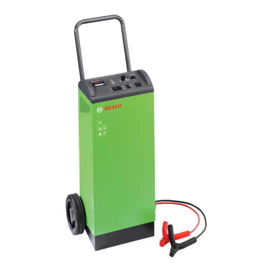
Bosch BSL 2470 Repair Instructions
Rapid start charger for 12/24 v batteries
Hide thumbs
Also See for BSL 2470:
- Original instructions manual (124 pages) ,
- Operating instructions manual (76 pages)
Table of Contents

Related Manuals for Bosch BSL 2470


Summary of Contents for Bosch BSL 2470
- Page 1 Repair instructions BSL 2470 0 687 000 100 Rapid start charger for 12/24 V batteries...
-
Page 2: Table Of Contents
Inhalt: Seite Important note Test equipment and tools Testing closed unit Battery charger design Wiring diagram Block diagram Printed circuit board Testing and troubleshooting on opened unit Testing power supplies Testing Triac Testing battery charge current... -
Page 3: Important Note
Important note Test equipment and tools - Multirange meter, e.g. Bosch MMD 302 (0 684 500 302) Electrical systems and resources may only be or commercial one. put into operation when they are in proper - portable multiscope, e.g. PMS 100 (0 684 416 100) -
Page 4: Testing Closed Unit
Testing closed unit Switch off battery charger Turn potentiometer to left-hand limit stop Set change-over switch for battery temperature to "hot" Set change-over switch for battery voltage to "12 V" Connect battery charger to mains via isolation transformer Switch on battery charger Red LED on? Switch off battery charger Unplug power cord! - Page 5 Set change-over switch for battery voltage to "12 V" Connect test battery to correct terminals Replace LED Switch on battery charger Yellow LED on? Switch off battery charger Disconnect test battery Unplug power cord! Check LED Yellow LED ok? Replace PCB Does power relay switch? Does ammeter...
-
Page 6: Battery Charger Design
Use potentiometer to set higher battery charge current Is higher battery charge current Switch off battery charger displayed? Unplug power cord! Switch off battery charger Disconnect test battery Unplug power cord! Battery charger design 12, 13 12, 14 12, 15 19, 20 Fig. -
Page 7: Wiring Diagram
Wiring diagram 451000118Lt Fig. 3 SL Rückwand SL rear panel gn/ge gr/ye Trafo P Trans. P Frontpl. Front plate... - Page 8 Ladeleitung B+ X4 X3 Amperemeter ge sw 451000119Lt Rückwand gn/ge Fig. 4 Amperemeter Ammeter Rückwand Rear panel Netzanschlussleitung Power cord Netztransformator Power transformer gn/ge grn/yel Netztransformator Power transformer Kühlblech-Gleichrichter Rectifier cooling plate Ladeleitung B+ B+ charging cable...
-
Page 9: Block Diagram
Block diagram Schutzschalter Temperatursicherung Temperatursicherung Overload switch Temperature Guard Temperature Guard A-0701-15A S3M. 184. 05 (*) S01-150. 05 (*) X12/3 X12/1 1 684 529 074 Triac BTA25-600B 8 940 001 202 Amperemeter Ammeter 1 687 235 296 Leistungsrelais High-current relay 0 333 335 006 24 V Anschlussleitung B+ / B-... -
Page 10: Testing And Troubleshooting On Opened Unit
Testing and troubleshooting on opened Testing Triac unit Checking the Triac control on the printed circuit board When testing, check for signs of intermittent contacts, contami- A clocked D.C. voltage must be applied to the printed nated and corrosive plug contacts, as well as any kinking and circuit board between P3 and P7. - Page 12 BSL 2470 0 687 000 100 Robert Bosch GmbH Automotive Aftermarket Test Equipment Post Box 1129 D 73201 Plochingen, Germany www.bosch.de/prueftechnik Email: [email protected]...