
Related Manuals for Emerson Rosemount 3051D


Summary of Contents for Emerson Rosemount 3051D
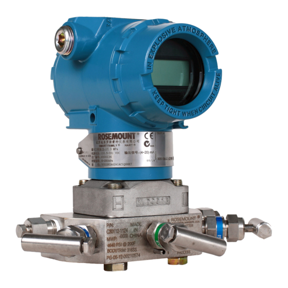
- Page 1 Quick Start Guide 00825-0100-5007, Rev CB February 2019 ™ Rosemount 3051 Pressure Transmitter...
- Page 2 Explosion-proof, Flameproof, or intrinsically safe (I.S.) installations. Refer to Rosemount 3051 Reference Manual for more instructions. This manual is also available electronically at Emerson.com/Rosemount. WARNING Explosions could result in death or serious injury.
-
Page 3: System Readiness
Verify the latest device driver (DD/DTM ) is loaded on your systems to ensure proper communications. • Download the latest device driver at Emerson.com Fieldcommgroup.org. Rosemount 3051 device revisions and drivers Table 1-1 provides the information necessary to ensure you have the correct device driver and documentation for your device. - Page 4 It is recommended to download new Device Driver files to ensure full functionality. HART Revision 5 and 7 Selectable, local operator interface (LOI), scaled variable, configurable alarms, expanded engineering units. Rosemount 3051G Pressure Transmitter updated electronics hardware design. Intrinsic Safety temperature classification change. Emerson.com/Rosemount...
-
Page 5: Transmitter Installation
February 2019 Quick Start Guide Transmitter installation Mount the transmitter 2.1.1 Liquid applications Procedure 1. Place taps to the side of the line. 2. Mount beside or below the taps. 3. Mount the transmitter so that the drain/vent valves are oriented upward. - Page 6 February 2019 Figure 2-2: Coplanar and In-line Gas Applications Flow A. Coplanar B. In-line 2.1.3 Steam applications Procedure 1. Place taps to the side of the line. 2. Mount beside or below the taps. 3. Fill impulse lines with water. Emerson.com/Rosemount...
- Page 7 February 2019 Quick Start Guide Figure 2-3: Coplanar and In-line Steam Applications Flow A. Coplanar B. In-line Figure 2-4: Panel and pipe mounting 1. 5/6 x 1½ panel bolts are customer supplied. Quick Start Guide...
- Page 8 Bolts are typically carbon steel (CS) or stainless steel (SST). Confirm the material by viewing the markings on the head of the bolt and referencing Table 2-1. If bolt material is not shown in Table 2-1, contact a local Emerson representative for more information. Use the following bolt installation procedure: Procedure 1.
- Page 9 February 2019 Quick Start Guide 4. Torque the bolts to the final torque value using the same crossing pattern. See Table 2-1 for final torque value. 5. Verify that the flange bolts are protruding through the isolator plate before applying pressure. Table 2-1: Torque Values for the Flange and Flange Adapter Bolts Bolt material Head markings...
- Page 10 3. Re-tighten the housing rotation set screw to no more than 7 in-lb when desired location is reached. Figure 2-7: Housing Rotation Set Screw A. Housing rotation set screw (5/64-in.) Rosemount 3051D original position aligns with “H” side; Rosemount 3051G original position is the opposite side of bracket holes. Emerson.com/Rosemount...
- Page 11 February 2019 Quick Start Guide CAUTION Over rotation of housing may cause damage to module communication cable. Set the switches Procedure Set alarm and security switch configuration before installation as shown in Figure 2-8. 2. The alarm switch sets the analog output alarm to high or low. 3.
- Page 12 Shielded twisted pair cable should be used for best results. Use 24 AWG or larger wire that does not exceed 5,000 ft. (1500 m) in length. If applicable, install wiring with a drip loop. Arrange the drip loop so the bottom is lower than the conduit connections and the transmitter housing. Emerson.com/Rosemount...
- Page 13 February 2019 Quick Start Guide CAUTION Installation of the transient protection terminal block does not provide transient protection unless the Rosemount 3051 case is properly grounded. Do not run signal wiring in conduit or open trays with power wiring, or near heavy electrical equipment.
- Page 14 2.4.1 Verifying configuration with a Field Communicator A Rosemount 3051 DD must be installed on the Field Communicator to verify configuration. Fast Key sequences for the latest DD are shown in Table 2-2. For Fast Key sequences using legacy DD's, contact your local Emerson representative. Emerson.com/Rosemount...
- Page 15 February 2019 Quick Start Guide Note Emerson recommends installing the latest DD to access the complete functionality. Visit Fieldcommunicator.com for information on updating the DD Library. Procedure Verify device configuration using the Fast Key sequences in Table a) A check (P) indicates the basic configuration parameters. At minimum, these parameters should be verified as part of configuration and startup.
- Page 16 To activate the LOI, push any button. LOI button functionality is shown on the bottom corners of the display. See Table 2-3 and Figure 2-12 for button operation and menu information. Figure 2-11: Internal and External LOI Buttons A. Internal buttons B. External buttons Emerson.com/Rosemount...
- Page 17 February 2019 Quick Start Guide Table 2-3: LOI Button Operation Button Left SCROLL Right ENTER Figure 2-12: LOI Menu Assign PV HART Revision 2.4.3 Switch HART revision mode If the HART configuration tool is not capable of communicating with HART Revision 7, the Rosemount 3051 will load a generic menu with limited capability.
- Page 18 O (compared to factory settings) values outside this range will be rejected by the transmitter. 2.5.1 Trimming with a Field Communicator Procedure 1. Connect the Field Communicator. See "Connect the wiring and power up" for instructions. 2. Follow the HART menu to perform the desired zero trim. Emerson.com/Rosemount...
- Page 19 February 2019 Quick Start Guide Table 2-4: Zero Trim Fast Keys Analog zero (Set 4 mA) Digital zero Fast Key sequence 3, 4, 2 3, 4, 1, 3 Figure 2-13: External Configuration Buttons A. LOI B. Analog zero and span C.
-
Page 20: Safety Instrumented Systems Installation
Quick Start Guide February 2019 Safety instrumented systems installation For safety certified installations, refer to Reference Manual for installation procedure and system requirements. Emerson.com/Rosemount... -
Page 21: Product Certifications
February 2019 Quick Start Guide Product Certifications Rosemount 3051D Pressure Transmitter Rev 2.10 European Directive Information A copy of the EC Declaration of Conformity can be found at the end of the Quick Start Guide. The most recent revision of the EC Declaration of Conformity can be found at Emerson.com/Rosemount. - Page 22 II 3 G Ex nA IIC T5 Gc (–40 °C ≤ T ≤ +70 °C), II 1 D Ex ta IIIC T95 °C T 105 °C Da (–20 °C ≤ T ≤ +85 °C) Special Conditions for Safe Use (X): Emerson.com/Rosemount...
- Page 23 February 2019 Quick Start Guide 1. The equipment is not capable of withstanding the 500V insulation test required by clause 6.5.1 of EN60079-15:2010. This must be taken into account when installing the equipment. 2. Some variants of the equipment have reduced markings on the nameplate.
- Page 24 E3 China Flameproof Certificate GYJ18.1023X Standards GB3836.1-2010, GB3836.2-2010, GB3836.20-2010 Markings Ex d IIC T6/T5 Ga/Gb Special Conditions for Safe Use (X): 1. The relation between ambient temperature range and temperature class is as follows: Temperature class –50 +70 °C Emerson.com/Rosemount...
- Page 25 February 2019 Quick Start Guide –50 +65 °C When used in a combustible dust environment, the maximum ambient temperature is 70 °C. 2. The earth connection facility in the enclosure should be connected reliably. 3. Cable entry certified by notified body with type of protection Ex d IIC in accordance with GB3836.1-2010 and GB3836.2-2010, should be applied when installed in a hazardous location.
- Page 26 A copy of the EC Declaration of Conformity can be found at the end of the Quick Start Guide. The most recent revision of the EC Declaration of Conformity can be found at Emerson.com/Rosemount. Ordinary Location Certification As standard, the transmitter has been examined and tested to determine that...
- Page 27 February 2019 Quick Start Guide 1. The Rosemount 3051 transmitter housing contains aluminum and is considered a potential risk of ignition by impact or friction. Care must be taken into account during installation and use to prevent impact and friction. 2.
- Page 28 7. Unused cable entries must be filled with suitable blanking plugs which maintain the ingress protection of the enclosure to at least IP66. 8. Cable entries and blanking plugs must be suitable for the ambient range of the apparatus and capable of withstanding a 7J impact test. Emerson.com/Rosemount...
- Page 29 February 2019 Quick Start Guide 9. Rosemount 2088/2090 sensor module must be securely screwed in place to maintain the ingress protection of the enclosure. 10. Some variants of the equipment have reduced markings on the nameplate. Refer to the Certificate for full equipment marking. I1 ATEX Intrinsic Safety and Dust Certificate BAS00ATEX1166X...
- Page 30 4. Appropriate cable, glands and plugs need to be suitable for a temperature of 5 °C greater than maximum specified temperature for location where installed. I7 IECEx Intrinsic Safety Certificate IECEx BAS 12.0071X Standards IEC60079-0:2011, IEC60079-11:2011 Markings Ex ia IIC T4 Ga (–55 °C ≤ T ≤ +70 °C) Emerson.com/Rosemount...
- Page 31 February 2019 Quick Start Guide Table 4-5: Entity Parameters Parameters HART Voltage U 30 V Current I 200 mA Power P 0.9 W Capacitance C 0.012 µF Inductance L 0 mH Special Conditions for Safe Use (X): 1. If the apparatus is fitted with optional 90V transient suppressor, it is not capable of withstanding the 500 V insulation test required by IEC60079-11.
- Page 32 7. When installation, use and maintenance of this product, observe following standards: GB3836.13-2013 “Explosive atmospheres-Part 13: Equipment repair, overhaul and reclamation” GB3836.15-2000 “Electrical apparatus for explosive gas atmospheres Part 15: Electrical installations in hazardous area (other than mines)” GB3836.16-2006 “Electrical apparatus for explosive gas atmospheres Part 16: Inspection Emerson.com/Rosemount...
- Page 33 February 2019 Quick Start Guide an maintenance of electrical installation (other than mines)” GB50257-2014 “Code for construction and acceptance of electric device for explosion atmospheres and fire hazard electrical equipment installation engineering”. I3 China Intrinsic Safety Certificate GYJ15.1301X Standards GB3836.1-2010, GB3836.4-2010, GB3836.20-2010 Markings Ex ia IIC T4 Ga (–55 °C ≤...
- Page 34 (IP) of the enclosure. 2. The blanking plug shall not be used with an adapter. 3. Blanking Plug and Threaded Adapter shall be either NPT or Metric thread forms. G½ thread forms are only acceptable for existing (legacy) equipment installations. Emerson.com/Rosemount...
- Page 35 February 2019 Quick Start Guide EU Declaration of Conformity EU Declaration of Conformity No: RMD 1089 Rev. I Rosemount Inc. 8200 Market Boulevard Chanhassen, MN 55317-9685 declare under our sole responsibility that the product, Rosemount™ Models 3051D and 3051G Pressure Transmitters manufactured by, Rosemount Inc.
- Page 36 Ex ia IIC T5 Ga (-60°C ≤ Ta ≤ +40°C) Harmonized Standards Used: EN60079-0:2012+A11:2013, EN60079-11:2012 Baseefa12ATEX0190X - Type n Certificate Equipment Group II Category 3 G Ex nA IIC T5 Gc (-40°C ≤ Ta ≤ +70°C) Harmonized Standards Used: EN60079-0:2012+A11:2013, EN60079-15:2010 Page 2 of 4 Emerson.com/Rosemount...
- Page 37 February 2019 Quick Start Guide EU Declaration of Conformity No: RMD 1089 Rev. I Baseefa12ATEX0191 - Dust Certificate Equipment Group II Category 1 D 105°C Da (-20°C ≤ Ta ≤ +85°C) Ex ta IIIC T95°C T Harmonized Standards Used: EN60079-0:2012+A11:2013, EN60079-31:2009 DEKRA12ATEX0212X - Flameproof Certificate Equipment Group II Category 1/2 G Ex db IIC T6 Ga/Gb (-50°C ≤...
- Page 38 SGS FIMCO OY [Notified Body Number: 0598] P.O. Box 30 (Särkiniementie 3) 00211 HELSINKI Finland ATEX Notified Body for Quality Assurance SGS FIMCO OY [Notified Body Number: 0598] P.O. Box 30 (Särkiniementie 3) 00211 HELSINKI Finland Page 4 of 4 Emerson.com/Rosemount...
- Page 39 February 2019 Quick Start Guide China RoHS table Rosemount 3051 China RoHS List of Rosemount 3051 Parts with China RoHS Concentration above MCVs / Hazardous Substances Hexavalent Polybrominated Polybrominated Part Name Lead Mercury Cadmium Chromium biphenyls diphenyl ethers (Pb) (Hg) (Cd) (Cr +6) (PBB)
- Page 40 The Emerson logo is a Facebook.com/Rosemount trademark and service mark of Emerson Electric Youtube.com/user/ Co. Rosemount is mark of one of the Emerson RosemountMeasurement family of companies. All other marks are the Google.com/+RosemountMeasurement property of their respective owners.