Emerson CoreSense Technical Information
Diagnostics for stream refrigeration compressors
Hide thumbs
Also See for CoreSense:
- Technical information (17 pages) ,
- Application engineering bulletin (19 pages)
Table of Contents
Date of last update: Oct-11
™
™
C
S
C
S
O
R
E
E
N
S
E
O
R
E
E
N
S
E
CoreSense™ Diagnostics for Stream Refrigeration Compressors ............................................................................... 1
1
Introduction .......................................................................................................................................................... 3
2
Specifications ........................................................................................................................................................ 3
3
Emerson CoreSense™ Diagnostics - Features ..................................................................................................... 3
3.1
"Jog" feature ................................................................................................................................................. 4
3.2
Crankcase heater (CCH) control.................................................................................................................... 4
3.3
Insufficient oil pressure protection .............................................................................................................. 5
3.4
Motor overheat protection .......................................................................................................................... 5
3.5
High discharge temperature protection ....................................................................................................... 5
3.6
Locked rotor protection ................................................................................................................................ 5
3.7
Missing phase protection ............................................................................................................................. 5
3.8
Low voltage protection ................................................................................................................................. 5
3.9
Voltage imbalance protection ...................................................................................................................... 6
3.10
Flash memory information ........................................................................................................................... 6
3.10.1
The following asset information will be saved in the flash memory (EEPROM); ................................. 6
3.10.2
Compressor running status information will be saved in the flash memory (EEPROM): ..................... 6
3.10.3
Compressor Operating Parameters ...................................................................................................... 6
®
3.11
communication ............................................................................................................................. 6
3.12
Local and remote reset ................................................................................................................................. 6
3.13
Alarm history and running conditions .......................................................................................................... 7
3.14
Compressor status codes .............................................................................................................................. 7
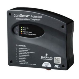
3.15
LEDs on the module to display the failure alarms ........................................................................................ 7
4
Electrical connections ........................................................................................................................................... 9
4.1
System wiring diagram ................................................................................................................................. 9
4.2
Terminal box and current sensing transformer connections ..................................................................... 10
4.2.1
Installation of current sensing module ............................................................................................... 10
4.2.2
CoreSense™ Diagnostics with Υ/Δ motors ........................................................................................ 11
Technical Information
D
D
I
A
G
N
O
S
T
I
C
S
F
O
I
A
G
N
O
S
T
I
C
S
F
O
S
R
S
R
R
T
R
E
A
M
E
F
R
I
R
T
R
E
A
M
E
F
R
I
Ref: D7.8.4/1011/E
Application Engineering Europe
C
C
G
E
R
A
T
I
O
N
O
M
P
R
G
E
R
A
T
I
O
N
O
M
P
E
S
S
O
R
S
R
E
S
S
O
R
S
1/17
Table of Contents

Related Manuals for Emerson CoreSense


Summary of Contents for Emerson CoreSense
-
Page 1: Table Of Contents
Date of last update: Oct-11 Ref: D7.8.4/1011/E Application Engineering Europe ™ ™ CoreSense™ Diagnostics for Stream Refrigeration Compressors ................1 Introduction ................................3 Specifications ................................ 3 Emerson CoreSense™ Diagnostics – Features ..................... 3 “Jog” feature ..............................4 Crankcase heater (CCH) control........................4 Insufficient oil pressure protection ...................... - Page 2 D7.21.2/1011/E Technical Information 4.2.3 CoreSense™ Diagnostics with part winding ..................11 CoreSense™ Diagnostics jumper settings ......................13 CoreSense™ Diagnostics DIP-Switch setting ..................... 13 Troubleshooting..............................15 2/17...
-
Page 3: Introduction
CoreSense™ is an ingredient brand name for compressor electronics associated with Emerson‟s Copeland® brand products. CoreSense™ technology uses compressor as a sensor to unlock information from within the compressor providing value added features such as advanced motor protection, diagnostics, communication. -
Page 4: Jog" Feature
D7.21.2/1011/E Technical Information Figure 2 “Jog” feature The reset button below the control module may be used as an emergency shutdown, such as for clearing liquid during a start-up. After the module re-boots (approximately 3 seconds) the compressor will run again. The reset button may be pushed as necessary to stop the compressor. -
Page 5: Insufficient Oil Pressure Protection
CoreSense™ will protect the compressor from high discharge temperature conditions. If the temperature sensor detects a discharge temperature higher than 154°C, the CoreSense™ will shut off the compressor until the temperature cools down to an acceptable level (about 130°C). -
Page 6: Voltage Imbalance Protection
The CoreSense™ Diagnostics module is equipped with a remote reset capability, such that if a compressor is off in a lockout condition, the user can remotely restart the compressor through their rack controller or compatible remote access software. -
Page 7: Alarm History And Running Conditions
Total number of alarms since the compressor first operation Compressor power consumption* Current, voltage, power factor* *This data is not stored in CoreSense™ EEPROM memory. These values can be stored in a laptop using CoreSense™ PC ® Interface Software or Modbus communication. - Page 8 D7.21.2/1011/E Technical Information Auto Lockout flashes Status LED description reset Status LED troubleshooting information condition count time Without flashing green, compressor has been Low Oil Low Oil sufficient oil without sufficient oil pressure for 4 seconds. Pressure Pressure pressure for 2 flashing red, compressor has been minutes...
-
Page 9: Electrical Connections
System wiring diagram Fuses and wire cable sizing must be done in accordance with all applicable electrical code standards. Figure 5 below shows the recommended basic system wiring for a compressor with CoreSense™. Figure 5: Wiring diagram Figure 6: CoreSense™ wiring terminals description... -
Page 10: Terminal Box And Current Sensing Transformer Connections
D7.21.2/1011/E Technical Information Figure 7: CoreSense™ module with current sensor Terminal box and current sensing transformer connections For space reasons inside the compressor terminal box wires L1 and L2 connected to the sensor module need to be exchanged in such a way that the black wire is connected to terminal 2 (V) and the white wire goes to terminal 1 (U) on the terminal plate as shown on the drawing. -
Page 11: Coresense™ Diagnostics With Υ/Δ Motors
4.2.3 CoreSense™ Diagnostics with part winding If using the CoreSense™ Diagnostics module with a part-winding start motor, one power lead of each of the windings should be passed through the current sensing transformer in the same direction (see Figures 10 and 11) to provide accurate compressor proofing. - Page 12 D7.21.2/1011/E Technical Information Figure 11: Wiring part winding Figure 12: Wiring Sensor module and leads routed through the current sensor 12/17...
-
Page 13: Coresense™ Diagnostics Jumper Settings
JP4 should be set “1-2” if connected to an iPro rack controller. Set JP4 to “2-3” for other pack controllers. Do not remove JP1. This is reserved for future use. Figure 13 CoreSense™ Diagnostics DIP-Switch setting Figure 14: CoreSense™ Diagnostics DIP-Switch setting 13/17... - Page 14 D7.21.2/1011/E Technical Information Assign a unique node address to each CoreSense™ diagnostics module using switches 1 through 5. a. Set the communications baud rate for the module using switch 7. “Off” = 19200 baud, “On” = 9600 baud. The baud rate for each module should be set to match the rack controller.
-
Page 15: Troubleshooting
If resistance is low, inspect for loose terminal strip connections, harness connection alarms occur. failure at circuit board, open harness circuit or high motor temp due to return gas ™ Faulty CoreSense module. temperature, motor voltage or load condition. Open discharge probe (faulty). - Page 16 Is there a communication network? If not, verify that the communication harness is ™ CoreSense control module and ™ Warning: Appears when there is no engaged at both the CoreSense module and the sensor module. rack controller has been lost. communication between control...
- Page 17 D7.21.2/1011/E Technical Information Flash Alarm conditions Possible failure reasons Troubleshooting measures code Supply voltage is in the Verify voltage supply from the main buss. specified range. Verify voltage into and out of contactor (repair or replace contactor if necessary). Loose wiring connections at the Measure voltage at the compressor terminal (refer to AE10-1244, Recommended Contactor Selection for 3-Phase Motor Control –...