
Related Manuals for Allen-Bradley 1762-OF4


Summary of Contents for Allen-Bradley 1762-OF4
-
Page 1: Table Of Contents
Installation Instructions Analog Output Module Catalog Number 1762-OF4 Table of Contents Topic Page Important User Information North American Hazardous Location Approval Additional Resources Overview Module Description Mount the Module Field Wiring Connections Grounding the Module Output Type Selection Wiring the Finger-Safe Terminal Block... -
Page 2: Important User Information
Analog Output Module Important User Information Solid state equipment has operational characteristics differing from those of electromechanical equipment. Safety Guidelines for the Application, Installation and Maintenance of Solid State Controls (Publication SGI-1.1 available from your local Rockwell Automation sales office or online at http://literature.rockwellautomation.com) describes some important differences between solid state equipment and hard-wired electromechanical devices. - Page 3 In addition to this publication, see: Industrial Automation Wiring and Grounding Guidelines, for additional installation requirements, Allen-Bradley publication 1770-4.1. NEMA Standards 250 and IEC 60529, as applicable, for explanations of the degrees of protection provided by different types of enclosure.
-
Page 4: North American Hazardous Location Approval
Analog Output Module North American Hazardous Location Approval The following modules are North American Hazardous Location approved: 1762-OF4 The following information applies when Informations sur l’utilisation de cet operating this equipment in hazardous équipement en environnements dangereux: locations: Products marked "CL I, DIV 2, GP A, B, C, D" are Les produits marqués "CL I, DIV 2, GP A, B, C, D"... -
Page 5: Additional Resources
Guidelines, publication 1770-4.1. techniques. If you would like a manual, you can: • download a free electronic version from the Internet: http://literature.rockwellautomation.com • purchase a printed manual by contacting your local Allen-Bradley distributor or Rockwell Automation representative Publication 1762-IN016D-EN-P - June 2013... -
Page 6: Overview
Analog Output Module Overview 1762 output module is suitable for use in an industrial environment when installed in accordance with these instructions. Specifically, this equipment is intended for use in clean, dry environments (Pollution degree 2 ) and to circuits not exceeding Over Voltage Category II (IEC 60664-1) Install your module using these installation instructions. -
Page 7: Module Description
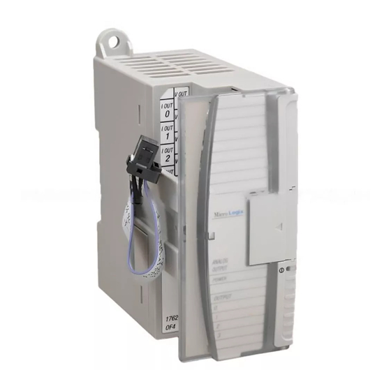
Analog Output Module Module Description 45156 45180 This equipment is sensitive to electrostatic discharge (ESD). Follow ESD prevention guidelines when handling this equipment. Left side view Front view Description Description upper panel mounting tab pull loop lower panel mounting tab module door with terminal identification label power diagnostic LED bus connector cover... -
Page 8: Mount The Module
Additional grounding connections from the power supply's mounting tabs or DIN rail (if used) are not required unless the mounting surface cannot be grounded. Refer to Industrial Automation Wiring and Grounding Guidelines, Allen-Bradley publication 1770-4.1, for additional information. Mounting Dimensions 90 mm (3.5 in.) - Page 9 Before mounting the module on a DIN rail, close the DIN rail latch. Press the DIN rail mounting area of the module against the DIN rail. The latch will momentarily open and lock into place. Use DIN rail end anchors (Allen-Bradley part number 1492-EA35 or 1492-EAH35) for vibration or shock environments. End anchor...
- Page 10 Analog Output Module Panel Mounting Use the dimensional template shown below to mount the module. The preferred mounting method is to use two M4 (#8) panhead screws per module. M3.5 (#6) panhead screws may also be used, but a washer may be needed to ensure a good mechanical contact. Mounting screws are required on every module.
-
Page 11: Field Wiring Connections
Analog Output Module Field Wiring Connections Grounding the Module In solid-state control systems, grounding and wire routing helps limit the effects of noise due to electromagnetic interference (EMI). Run the ground connection from the ground screw of the controller to the ground bus prior to connecting any devices. Use AWG #14 wire. For AC-powered controllers, this connection must be made for safety purposes. - Page 12 Analog Output Module Output Wiring Basic wiring of input devices to the 1762-OF4 is shown below. Terminal Block Layout V out 0 I out 0 V out 1 I out 1 V out 2 I out 2 V out 3...
-
Page 13: Wiring The Finger-Safe Terminal Block
Analog Output Module Wiring the Finger-Safe Terminal Block 45161 ATTENTION Be careful when stripping wires. Wire fragments that fall into a module could cause damage when power is applied. Once wiring is complete, ensure the module is free of all metal fragments. When wiring the terminal block, keep the finger-safe cover in place. - Page 14 Analog Output Module Labeling the Terminals A write-on label is provided with the module. Mark the identification of each terminal with permanent ink, and slide the label back into the door. 1762 Expansion I/O Addressing The addressing scheme for 1762 Expansion I/O is represented in the following figure. Output Data file (0) Slot number Word...
- Page 15 Analog Output Module • UOx = Under-range flag bits for output channels 0…3. These bits indicate an input signal below the user range. They can be used in the control program for error detection. The module continues to convert analog data to the minimum full range value while this bit is set (1).
- Page 16 Analog Output Module Configuration Data File The configuration of the format for analog outputs is made at going to run (GTR). Changes made to the configuration file while in run mode have no effect on the outputs. The configuration table for analog outputs is shown in the Configuration Data File table. Configuration Data File Bit Position 15 14...
- Page 17 Analog Output Module Type/Range Select (Bits 11…8) These bits indicate the type and range as in the following table. Other combinations of these bits are not supported and result in an error. Bit Settings Data Format Voltage Mode 0…10V DC Current Mode 4…20 mA other Not Supported...
-
Page 18: Specifications
Analog Output Module Specifications Output Attribute Value Number of outputs 4 single-ended (unipolar) D/A converter type R-2R Ladder Voltage Switching Module update time 2.5 ms Resistive load on current output 0…500 (includes wire resistance) Load range on voltage output > 1K Reactive load, current output <... - Page 19 Analog Output Module General Attribute Value Dimensions, HxWxD 90 x 40.4 x 87 mm (3.54 x 1.59 x 3.43 in.) Approximate shipping weight 235 g (8.28 oz) (with carton) Bus current draw, max 40 mA @ 5V DC 165 mA @ 24V DC Analog normal operating range Voltage: 0…10V DC Current: 4…20 mA...
- Page 20 Analog Output Module Environmental Attribute Value Temperature, operating IEC 60068-2-1 (Test Ad, Operating Cold), IEC 60068-2-2 (Test Bd, Operating Dry Heat), IEC 60068-2-14 (Test Nb, Operating Thermal Shock): -20... 65 °C (-4...149 °F) Temperature, storage IEC 60068-2-1 (Test Ab, Unpackaged Non-operating Cold), IEC 60068-2-2 (Test Bb, Unpackaged Non-operating Dry Heat), IEC 60068-2-14 (Test Na, Unpackaged Non-operating Thermal Shock): -40…85 °C (-40…185 °F)
- Page 21 Analog Output Module Certifications Certification (when Value product is marked) c-UL-us UL Listed Industrial Control Equipment, certified for US and Canada. See UL File E322657. UL Listed for Class I, Division 2 Group A,B,C,D Hazardous Locations, certified for U.S. and Canada. See UL File E334470. European Union 2004/108/EC EMC Directive, compliant with: EN 61326-1;...
- Page 22 Analog Output Module Notes: Publication 1762-IN016D-EN-P - June 2013...
- Page 23 Analog Output Module Notes: Publication 1762-IN016D-EN-P - June 2013...
- Page 24 RA-DU002, available at http://www.rockwellautomation.com/literature/. Allen-Bradley, Rockwell Automation, MicroLogix, and TechConnect are trademarks of Rockwell Automation, Inc. Trademarks not belonging to Rockwell Automation are property of their respective companies. Publication 1762-IN016D-EN-P - June 2013 Supersedes Publication 1762-IN016C-EN-P - March 2011 Copyright ©...