Quick Links
DB7110U Universal Heat Pump
Defrost Controller
APPLICATION
The DB7110U Universal Heat Pump Defrost
Controller is a heat pump defrost control used in
single stage heat pump appliances. This product
replaces over 260 OEM and competitive controls and
can be easily programmed to meet the requirements
of virtually any single stage heat pump. See Table 2,
"Compatibility Chart.," on page 5.
FEATURES
The DB7110U provides:
• Universal defrost control for single stage heat
pumps
• LED display for easy setup and configuration
• Small, square footprint for easier installation
• Demand and timed defrost modes
• System status and fault indication
• Selectable reversing delay to limit noise when
going in and out of a defrost cycle
• Fault history for easy troubleshooting
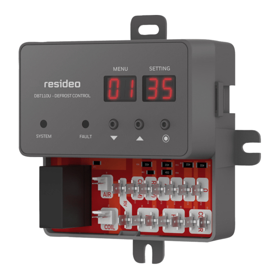
DB7110U-DEFROST CONTROL
SYSTEM
FAULT
Fig. 1. DB7110U1000.
MENU
SETTING
M37637
INSTALLATION INSTRUCTIONS
SPECIFICATIONS
Electrical Ratings
Input Voltage: 24VAC, 60Hz
Max. Input Current: 200mA
Compressor Contactor: 1A @ 24VAC
Outdoor Fan:
1/2HP motor
5A full load, 30A locked rotor, 240VAC.
Aux Heat: 1A @ 24VAC
Reversing Valve: 1A @ 24VAC
All outputs rated for 100,000 operations.
All terminals except FAN-IN and FAN-OUT are NEC
Class 2 low voltage.
Environmental Ratings
Operating Temperature Range: -40F to 150F
Humidity Limits: less than 95% (non-condensing)
INSTALLATION AND
CONFIGURATION
Overview
When Installing This Product...
1. Read these instructions carefully. Failure to fol-
low instructions can damage the product or
cause a hazardous condition.
2. Check ratings given in these instructions and
on the product to make sure the product is suit-
able for your application.
3. Installer must be a trained, experienced service
technician.
4. Use these instructions to check out the product
operation after installation.
34-00032-01

Related Manuals for Honeywell DB7110U1000


Summary of Contents for Honeywell DB7110U1000
- Page 1 3. Installer must be a trained, experienced service technician. M37637 4. Use these instructions to check out the product Fig. 1. DB7110U1000. operation after installation. 34-00032-01...
-
Page 2: Control Location
DB7110U UNIVERSAL HEAT PUMP DEFROST CONTROLLER WARNING Electrical Shock Hazard. Can cause severe injury, death or property damage. Disconnect power supply before beginning installation to prevent electrical shock or SENSOR equipment damage. More than one disconnect may be involved. Control Location 1. - Page 3 DB7110U UNIVERSAL HEAT PUMP DEFROST CONTROLLER 3. Check the line voltage connections on the fan relay to ensure they are tight, in good connec- OUTDOOR INDOOR DB7110U EQUIPMENT tion, and more than 1/4" away from any part of EQUIPMENT the appliance enclosure. FAN-OUT 4.
- Page 4 DB7110U UNIVERSAL HEAT PUMP DEFROST CONTROLLER The displayed coil and air temperature readings can be very useful for optimizing and trouble- INDOOR OUTDOOR EQUIPMENT EQUIPMENT DB7110U shooting defrost performance. FAN-OUT 3. There are several configurable options to opti- FAN-IN mize defrost performance. See “User Interface” on page 7 for a detailed description of each REVERSING VALVE...
-
Page 5: Compatibility Chart
47-102685-02 47-102685-03 PCBDM101S PCBDM130S 47-102685-04 47-102685-05 Heil Quaker HQ1052727 47-102685-06 47-102685-84 Heil/Tempstar 1087952 1087953 47-21517-11 47-21517-13 1173636 CEPL130524-01 47-21517-14 47-21517-16 Honeywell ST74A1004 ST74A1020 47-21517-17 47-21517-18 ST74A1038 ST74A1053 47-21517-22 47-21517-23 ST74C1002 47-21517-24 47-21517-82 DFORB24A21300 ICM300C 47-21517-88 47-21517-92 DFORB-AB1004 DFORF 47-21776-01 47-21776-06... - Page 6 DB7110U UNIVERSAL HEAT PUMP DEFROST CONTROLLER Table 2. Compatibility Chart. (Continued) Tempstar/ICP 1084-100 1084-83-1008 1087562 Therm-O Disc 26E-09 Trane 21C14501G18 21C1450127 21C1450136 21C1450137 21C1450138 21C1450142 21C1450144 21C1450145 21C1450153 21C1450154 21C1450155 21C1450160 21C14282G01 CNT01106 CNT01108 CNT01129 CNT01152 CNT01431 CNT01510 CNT01642 CNT01923 CNT01924 CNT01926 CNT02514...
-
Page 7: User Interface
DB7110U UNIVERSAL HEAT PUMP DEFROST CONTROLLER USER INTERFACE The user interface consists of three buttons, two LED’s, and 4 7-segment digits. The two left digits generally represent the category of what is being displayed while the two right digits represent the value or setting of the category. - Page 8 DB7110U UNIVERSAL HEAT PUMP DEFROST CONTROLLER Table 4. Configuration Screens. (Continued) Display Description Range Default Reverse Delay 0-30 seconds 30 seconds Compressor off time when switching between heating and defrost modes. Setting this to 0 will shorten the overall defrost time, but may result in objectionably loud noises when entering/exiting defrost (depending on compressor type).
-
Page 9: Troubleshooting And Maintenance
DB7110U UNIVERSAL HEAT PUMP DEFROST CONTROLLER TROUBLESHOOTING AND MAINTENANCE IMPORTANT Due to the potential hazard of line voltage, only a trained experienced service technician should perform the troubleshooting procedures. This control contains no field-serviceable parts. Do not attempt to take it apart. Replace the entire control if operation is not as described. - Page 10 DB7110U UNIVERSAL HEAT PUMP DEFROST CONTROLLER Table 5. Troubleshooting. (Continued) Condition Procedure Control Status Corrective Action System does not Observe operational Display shows COOL • O/b configured incorrectly. Verify defrost at all mode while heating. proper setting of O/b input for reversing valve control.
- Page 11 DB7110U UNIVERSAL HEAT PUMP DEFROST CONTROLLER Table 6. Fault Code Information. Fault No. Description Corrective Action Internal Communication Fault • Replace control Internal Fault • Replace control Low 24V • Measure 24V (R & C). There may be something in the system loading the 24V transformer excessively.
- Page 12 DB7110U UNIVERSAL HEAT PUMP DEFROST CONTROLLER Resideo Inc., 1985 Douglas Drive North, Golden Valley, MN 55422 www.resideo.com 34-00032—01 M.S. 12-18 | Printed in United States ©2018 Resideo Technologies, Inc. All rights reserved. The Honeywell Home trademark is used under license from Honeywell International Inc.