Table of Contents
1. APPLICATION
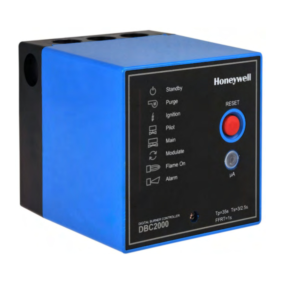
The Honeywell DBC2000 is a microprocessor-based
integrated burner controller for automatically fired
gas, oil or combination fuel industrial single burner
power burner applications. The DBC2000 system
consists of the relay module and wiring subbase.
The DBC2000 Standard Model provides the
minimum requirements to control an industrial
burner system, such as automatic burner
sequencing, flame supervision, system status
indication, system or self-diagnostics and
troubleshooting. The DBC2000 Enhanced Model
includes an integrated Valve Proofing System,
whilst the Ultimate model includes bus
communication on top of this.
The DBC2000 is programmed to provide a level of
safety, functional capability and features beyond
the capacity of conventional controls.
Important note:
Subject to changes without notice.
Please check our web site
http://hic.emea.honeywell.com
for the most recent version of this document.
All rights reserved.
DIGITAL BURNER CONTROLLER
PRODUCT HANDBOOK
2. FEATURES
•
Employs a plug-in mounting method
•
Uses a microprocessor to improve performance
•
Status and fault indication by indicator LEDs
•
A 4-wire firing rate switching circuit controls an air
damper motor or other auxiliary equipment during
start-up of the burner.
•
Safe start check before and during pre-purge
•
Dual flame amplifier for UV, IR or flame rod sensor
•
Automatic recycle once per 24h of uninterrupted
heat demand.
•
Frontal jack plug (Ø 3.5mm) to read the flame
signal with a microampere meter.
•
An electrical sub base lock (reset and safety limit
terminals are swapped) to avoid that a Standard
model is used systems wired for an Enhanced or
Ultimate model. The DBC2000 cannot start then.
•
Safety shutdown occurs on
malfunction of the burner controller
-
Failure To Ignite The Pilot burner or main burner
-
loss of flame during run period
-
opening of air flow switch during pre-purge, start-
-
up, run and post-purge period
flame signal detection during standby or pre-
-
purge period
•
Integrated Valve Proofing System (Enhanced and
Ultimate models only)
•
Remote bus communication (Ultimate model only)
1. Application
2. Features
Appendix: VPS calculation and diagrams
1
DBC2000 SERIES
Contents
1
1
2
5
6
12
14
23
25
ENS7003R16 KO65 2013
Table of Contents

Related Manuals for Honeywell DBC2000E10 Series


Summary of Contents for Honeywell DBC2000E10 Series
- Page 1 An electrical sub base lock (reset and safety limit 1. APPLICATION terminals are swapped) to avoid that a Standard model is used systems wired for an Enhanced or The Honeywell DBC2000 is a microprocessor-based Ultimate model. The DBC2000 cannot start then. integrated burner controller for automatically fired •...
-
Page 2: Specifications
The Ultimate model includes both remote bus communication and a Valve Proofing System. (*) xx depends on supply voltage and timings. For exact model number, please refer to product selection matrix ot technical catalogue on http://products.ecc.emea.honeywell.com/europe. Table 2: Sequence timing Standard Model... - Page 3 Table 4: Flame detection systems Max. lead wire Standard stable flame Detector Flame detector model no. lengths type current on jack plug UV detector C7027A, C7035A, C7044A < 100m 4µA (min) 14µA (max) Flame rod Flame rod or rectifying optical sensors, <...
- Page 4 Mains input: Supply voltage CAUTION 220 to 240Vac -15% +10% 50/60Hz or 110 to 120Vac -15% +10% 50/60Hz Although the voltage on the jack plug is of low voltage, it is not considered to be safe when touching Allowable ambient Temperature & Humidity the wires connected to the jack plug, in case of a -10 °C;...
-
Page 5: Dimensions
4. DIMENSIONS Fig. 1: External Dimensions (in mm) Fig. 2: Mounting dimensions of sub-base and terminal layout ENS7003R16 KO65 2013... -
Page 6: Installation And Wiring
5. INSTALLATION AND WIRING CAUTION 7. For on-off gas-fired systems, some authorities who have jurisdiction prohibit the wiring of any INSTALLATION limit or operating contacts in series between the flame safeguard control and the main fuel When Installing this Product… valve(s). - Page 7 3. When using Interrupted Pilot, connect the pilot REMOVE THE RELAY MODULE FROM ITS valve to Terminal 6. Connect the main valves to SUB BASE AND FIX THE SUB BASE Terminal 7 (Enhanced and Ultimate models: connect main valve 1 to Terminal 7 and main valve 1.
- Page 8 Note: terminals 18 and 19 are swapped for the Standard and Enhanced/Ultimate models. This is to prevent that a Standard model can be used by mistake in a system that is wired for an Enhanced or Ultimate model. Fig. 3-1: Terminal layout Fig.
- Page 9 Fig. 3-3: More examples of wiring to external equipment Fig. 4-1: Wiring a flame detector CAUTION There is line voltage on flame sensor inputs. Don’t touch the lead wires of the UV detector or the flame sensing electrode to avoid an electrical shock. ENS7003R16 KO65 2013...
- Page 10 Flame signal monitoring Fig. 4-2: Real flame current versus reading on frontal jack plug. Note: The flame signal strength on the flame current jack plug is only for reference and can vary between different DBC2000 devices. When measuring the flame signal current directly in the flame sensor wiring whilst: 1.
- Page 11 SETTING THE OPTIONAL FEATURES STD model: 1. Post-purge or no post-purge To enable DBI mode, apply line voltage to terminal 22 on the wiring base. Practically this Post-purge mode (default for all DBC2000E means that a jumper is placed between terminals models): before going to standby after heat 1 (L) and 22.
-
Page 12: Operation
6. OPERATION NORMAL OPERATION Table 7: Normal operation sequence Operation of DBC2000 and device Indicator LED * Inputs The power supply voltage is applied across Terminal 1 and HEAT DEMAND SW OFF 2. When no flame signal is present, the combustion airflow ●○○○○○○○... - Page 13 ENS7003R16 KO65 2013...
-
Page 14: Trouble Shooting
7. TROUBLE SHOOTING ERROR TYPES AND SAFE SHUTDOWN If a critical error related to safety operation (such as a loss of flame, opening of the air flow switch during the ignition trial and run sequence) is detected, the DBC2000 instantly goes into lock-out and goes to pre-purge status. If a non critical error is detected (such as opening of the air flow switch during post-purge), DBC2000 holds the sequence during the lock-out time, allowing time for the error to rectify, and then goes into lock- out. - Page 15 ENS7003R16 KO65 2013...
- Page 16 ENS7003R16 KO65 2013...
- Page 17 ENS7003R16 KO65 2013...
- Page 18 ENS7003R16 KO65 2013...
- Page 19 ENS7003R16 KO65 2013...
- Page 20 ENS7003R16 KO65 2013...
- Page 21 ENS7003R16 KO65 2013...
- Page 22 Table 8: Error condition and LED status Indicator LED Error condition Sequence status (*1) Safety limits opened at any time (no voltage present at T18 (STD model) or ●○○○○○○◐ T19 (ENH/ULT model) ●◐○○○○○◐ Air flow switch remains ON (closed) for more than 5 minutes, or START position interlock switch remains OFF(opened) for more than 5 minutes.
-
Page 23: Approvals And Maintenance
Conformity with the essential requirements of the EMC Directive 2004/108/EC on emission can only be determined in the application. This product is under surveillance at KIWA Nederland BV. Emmen, October 2011 Signed for and on behalf of Honeywell Technologies Sàrl, A.Veld Manager Standards & Approvals ENS7003R16 KO65 2013... - Page 24 Maintenance and service The designed lifetime* of this product is 10 years, based on date code, or 1.000.000 cycles under normal conditions, according to: a) the standard EN 298 b) the table on designed lifetime as stated on the Afecor website http://www.afecor.org/ We cannot assume that the product can be safely used beyond the mentioned designed lifetime.
- Page 25 APPENDIX: Calculations for VPS General Example 2 The maximum allowable leak-rate (according EN676 and EN746-2) is 0,1% of the maximum burner capacity. The test time necessary to detect a failing valve is a function of: Inlet pressure Test volume Burner capacity When the volume between two safety valves is bigger it takes more time (in case of a leaking valve) to change the status of the gas pressure switch (GPS).
- Page 26 Table a. Volumes in dm3 for gas valves like Honeywell VE-series (Vp) with pipe length L (including V1 and V2). For combi blocks, like VQ-M series and direct linked valves, use the values shown under L=0m. Length between valves [m]...
- Page 27 ENS7003R16 KO65 2013...
- Page 28 ENS7003R16 KO65 2013...
- Page 29 ENS7003R16 KO65 2013...
- Page 30 ENS7003R16 KO65 2013...
- Page 31 ENS7003R16 KO65 2013...
- Page 32 ENS7003R16 KO65 2013...
- Page 33 ENS7003R16 KO65 2013...
- Page 34 ENS7003R16 KO65 2013...