Allen-Bradley MicroLogix 1500 Installation Instructions Manual
Programmable controller base units
Hide thumbs
Also See for MicroLogix 1500:
- User manual (174 pages) ,
- Installation instructions manual (100 pages) ,
- Installation instructions (2 pages)
Table of Contents
Available languages
Available languages
Installation Instructions
MicroLogix™ 1500 Programmable
Controller Base Units
(Catalog Numbers 1764-24AWA, 1764-24BWA, and
1764-28BXB)
Inside...
English Section ....................................................................................... 3
Français ................................................................................................. 21
Deutscher Abschnitt ............................................................................. 41
Sezione in Italiano ................................................................................ 61
Sección en español............................................................................... 81
Seção em Português ........................................................................... 101
Publication 1764-IN001A-ML-P
Chapters
Table of Contents

Related Manuals for Allen-Bradley MicroLogix 1500


Summary of Contents for Allen-Bradley MicroLogix 1500
- Page 1 Installation Instructions MicroLogix™ 1500 Programmable Controller Base Units (Catalog Numbers 1764-24AWA, 1764-24BWA, and 1764-28BXB) Inside... English Section ..................3 Français ....................21 Deutscher Abschnitt ................41 Sezione in Italiano ................61 Sección en español................81 Seção em Português ................101 Publication 1764-IN001A-ML-P...
- Page 2 MicroLogix™ 1500 Programmable Controller Base Units Publication 1764-IN001A-ML-P...
-
Page 3: Table Of Contents
Installation Instructions English Section MicroLogix™ 1500 Programmable Controller Base Units (Catalog Numbers 1764-24AWA, 1764-24BWA, and 1764-28BXB) Inside... For More Information ................4 Overview ....................5 Base Unit Description ................6 Hazardous Location Considerations ............7 Mounting the Controller ................. 8 Wiring the Controller ................ -
Page 4: For More Information
Table 1 Related Publications Refer to this Document Pub. No. A more detailed description of how to MicroLogix 1500 1764-UM001A-US-P install and use your MicroLogix 1500 Programmable Controllers User programmable controller. Manual A reference manual that contains data and MicroLogix 1200 and... -
Page 5: Overview
MicroLogix™ 1500 Programmable Controller Base Units Overview Install your controller using these installation instructions. Do not remove protective debris strips until after the base and ATTENTION all other equipment in the panel near the base is mounted and wiring is complete. Once wiring is complete, remove protective debris strips and install processor unit. -
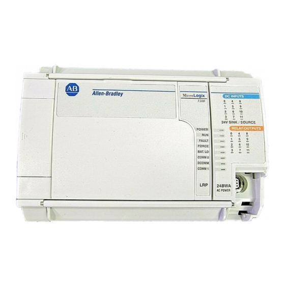
Page 6: Base Unit Description
MicroLogix™ 1500 Programmable Controller Base Units Base Unit Description Table 2 Standard Base Units Catalog Number Base Unit I/O and Power Supply 1764-24AWA 120V ac inputs/ relay outputs/ 120/240V ac power supply 1764-24BWA 24V dc inputs/ relay outputs/ 120/240V ac power supply 1764-28BXB 24V dc inputs/ FET and relay outputs/ 24V dc power supply Table 3 Base Unit Description... -
Page 7: Hazardous Location Considerations
MicroLogix™ 1500 Programmable Controller Base Units Hazardous Location Considerations This equipment is suitable for use in Class I, Division 2, Groups A, B, C, D or non-hazardous locations only. The following WARNING statement applies to use in hazardous locations. EXPLOSION HAZARD WARNING •... -
Page 8: Mounting The Controller
(catalog numbers 1769-CRR1, -CRR3, -CLL1, -CLL3, -CRL1, -CRL3) must be used at the end of the group of I/O modules attached to the MicroLogix 1500 Controller. The end cap terminator is not provided with the base unit. A maximum of eight I/O modules may be connected to the base. - Page 9 MicroLogix™ 1500 Programmable Controller Base Units Mounting Dimensions Table 5 Dimensions Dimension 1764-24AWA 1764-24BWA 1764-28BXB Height (A) 138 mm (5.43 in.) Width (B) 168 mm (6.62 in.) Depth (C) 87 mm (3.43 in.) Controller Spacing The base unit is designed to be mounted horizontally, with the Compact™ expansion I/O extending to the right of the base unit.
- Page 10 MicroLogix™ 1500 Programmable Controller Base Units Using a DIN Rail The base unit and expansion I/O DIN rail latches lock in the open position so that an entire system can be easily attached to or removed from the DIN rail. The maximum extension of the latch is 15 mm (0.67 in.) in the open position.
- Page 11 MicroLogix™ 1500 Programmable Controller Base Units To remove your base unit from the DIN rail: 1. Place a flat-blade screwdriver in the DIN rail latch at the bottom of the base unit. 2. Holding the base unit, pry downward on the latch until the latch locks in the open position.
-
Page 12: Wiring The Controller
MicroLogix™ 1500 Programmable Controller Base Units To install your base unit using mounting screws: 1. Remove the mounting template from the inside back cover of this document. 2. Secure the template to the mounting surface. (Make sure your base unit is spaced properly, see “Controller Spacing”... - Page 13 MicroLogix™ 1500 Programmable Controller Base Units Wire Requirements Table 7 Wire Type Recommendation Wire Type Wire Size (2 wire maximum per terminal screw) Solid Cu-90°C (194°F) #14 to #22 AWG Stranded Cu-90°C (194°F) #14 to #22 AWG Wiring torque = 1.13 Nm (10 in-lb) rated; 1.3 Nm (12 in-lb) maximum Be careful when stripping wires.
- Page 14 The diameter of the terminal screw head is 5.5 mm (0.220 in.). The input and output terminals of the MicroLogix 1500 base unit are designed for the following spade lugs. The terminals will accept a 6.35mm (0.25 in.) wide spade (standard for #6 screw for up to 14AWG) or a 4 mm (metric #4) fork terminal.
- Page 15 MicroLogix™ 1500 Programmable Controller Base Units Grounding the Controller ATTENTION All devices connected to the RS-232 channel must be referenced to base unit ground or floating. Failure to follow this procedure may result in property damage or personal injury. In solid-state control systems, grounding and wire routing helps limit the effects of noise due to electromagnetic interference (EMI).
-
Page 16: Specifications
MicroLogix™ 1500 Programmable Controller Base Units Specifications Table 8 General Specifications Description 1764-24BWA 1764-24AWA 1764-28BXB Number of I/O 12 inputs 12 inputs 16 inputs 12 outputs 12 outputs 12 outputs Line Power 85/265V ac 85/265V ac 20.4 to 30V dc Power Supply Inrush 120V ac = 25A 120V ac = 25A... - Page 17 MicroLogix™ 1500 Programmable Controller Base Units Table 9 Input Specifications Description 1764-24AWA 1764-24BWA and 1764-28BXB Inputs 0 thru 7 Inputs 8 and Higher On State Voltage 79 to 132V ac 14 to 30.0 V dc at 30°C 10 to 30.0 V dc at 30°C Range (86°F) (86°F)
- Page 18 MicroLogix™ 1500 Programmable Controller Base Units Table 12 1764-28BXB FET Output Specifications Specification General Operation High Speed Operation (Outputs 2 thru 7) (Outputs 2 and 3 Only) User Supply Voltage minimum 20.4V dc 20.4V dc maximum 26.4V dc 26.4V dc On-State Voltage at maximum load 1V dc...
- Page 19 MicroLogix™ 1500 Programmable Controller Base Units Table 13 Working Voltage Specification 1764-L24AWA Power Supply Input to Backplane Verified by one of the following dielectric tests: 1836V Isolation ac for 1 second or 2596V dc for 1 second 265V Working Voltage (IEC Class 2 reinforced insulation) Input Group to Backplane Isolation and Verified by one of the following dielectric tests: 151V...
- Page 20 MicroLogix™ 1500 Programmable Controller Base Units Table 13 Working Voltage Specification 1764-28BXB Input Group to Backplane Isolation and Verified by one of the following dielectric tests: 1200V Input Group to Input Group Isolation ac for 1 second or 1697V dc for 1 second 75V dc Working Voltage (IEC Class 2 reinforced insulation) FET Output Group to Backplane Isolation...
- Page 21 Notice d'installation Français Unité de base de l'automate programmable MicroLogix™ 1500 (Références 1764-24AWA, 1764-24BWA et 1764-28BXB) Contenu Pour plus d'informations ............... 22 Généralités.................... 23 Description de l'unité de base .............. 24 Environnements dangereux ..............25 Montage de l'automate ................ 26 Câblage de l'automate................
-
Page 22: Pour Plus D'informations
Pour plus d'informations Table 1 Publications associées Pour Lisez ce document Référence Plus de détails sur l'installation et MicroLogix 1500 Programmable 1764-UM001A-US-P l'utilisation de l'automate programmable Controllers User Manual MicroLogix 1500. Un manuel de référence contenant des MicroLogix™ 1200 and 1762-RM001B-US-P fichiers de données et de fonctions, un... -
Page 23: Généralités
Unité de base de l'automate programmable MicroLogix™ 1500 Généralités Suivez ces instructions pour installer votre automate. N’enlevez les bandes de protection contre les débris qu’après ATTENTION avoir monté la base et les autres équipements du panneau et après avoir terminé le câblage. Cela fait, enlevez les bandes de protection et installez le processeur. -
Page 24: Description De L'unité De Base
Unité de base de l'automate programmable MicroLogix™ 1500 Description de l'unité de base Table 2 Unités de base standard Référence E/S de l'unité de base et alimentation 1764-24AWA Entrée 120 V c.a./ sortie relais/ alimentation 120/240 V c.a. 1764-24BWA Entrée 24 V c.c./ sortie relais/ alimentation 120/240 V c.a. 1764-28BXB Entrée 24V c.c./sorties relais et FET/ alimentation 24 V c.c. -
Page 25: Environnements Dangereux
Unité de base de l'automate programmable MicroLogix™ 1500 Environnements dangereux Cet équipement est conçu pour être utilisé dans des environnements de Classe 1, Division 2, Groupes A, B, C, D ou non dangereux. La mise en garde suivante s’applique à une utilisation dans des environnements dangereux. DANGER D’EXPLOSION MISE EN GARDE •... -
Page 26: Montage De L'automate
Unité de base de l'automate programmable MicroLogix™ 1500 Montage de l'automate Considérations générales La plupart des applications exigent que l'automate soit installé dans une armoire industrielle (Niveau de pollution 2) pour limiter les perturbations dues aux interférences électriques (Catégorie II de surtension) et à l'environnement. Placez l'automate loin des lignes secteur, lignes de charge et autres sources de parasites électriques telles qu'interrupteurs câblés, relais et circuits de moteur c.a. - Page 27 Unité de base de l'automate programmable MicroLogix™ 1500 Dimensions de montage Table 5 Dimensions Dimensions 1764-24AWA 1764-24BWA 1764-28BXB Hauteur (A) 138 mm Largeur (B) 168 mm Profondeur (C) 87 mm Dégagements L’unité de base est conçue pour être montée horizontalement avec les E/S Compact™...
- Page 28 Unité de base de l'automate programmable MicroLogix™ 1500 Montage sur rail DIN Les loquets du rail DIN de l’unité de base et de l’extension d'E/S se verrouillent en position ouverte, permettant ainsi le montage ou le retrait de systèmes modulaires entiers. L’extension maximale du loquet en position ouverte est de 15 mm.
- Page 29 Unité de base de l'automate programmable MicroLogix™ 1500 Pour retirer l’unité de base du rail DIN : 1. Insérez la pointe d'un tournevis plat dans le loquet du rail DIN au bas de l’unité de base. 2. Tenez bien l'unité de base et pressez le loquet vers le bas jusqu’à ce qu'il s’enclenche en position ouverte.
- Page 30 Unité de base de l'automate programmable MicroLogix™ 1500 Montage par vis Montez sur panneau avec des vis n 8 ou M4. Gabarit de montage Pour installer l'unité de base avec des vis : 1. Découpez le gabarit de montage figurant au dos de la couverture. 2.
-
Page 31: Câblage De L'automate
Unité de base de l'automate programmable MicroLogix™ 1500 Câblage de l'automate Schémas de montage des borniers I / 1 I / 3 I / 4 I / 6 I / 9 I / 11 +24V COM 0 COM 2 POWER 24BWA I / 2 I / 5... - Page 32 La borne à vis a un diamètre de 5,5 mm. Les bornes d'entrée et de sortie de l'automate MicroLogix 1500 sont conçues pour les cosses suivantes : cosse plate de 6,35 mm de largeur ou cosse fourche de 4 mm (n Lorsque vous utilisez des cosses, soulevez le protège-doigts avec la pointe d’un...
- Page 33 Unité de base de l'automate programmable MicroLogix™ 1500 Suppression des surtensions Les appareils à charge inductive tels que les démarreurs et les ATTENTION électro-aimants nécessitent l'utilisation de dispositifs de suppression de surtension pour la protection des contacts de sortie de l'automate. Le changement de charges inductives sans protection contre les surtensions peut sensiblement réduire la durée de vie des contacts à...
-
Page 34: Spécifications
Unité de base de l'automate programmable MicroLogix™ 1500 Spécifications Table 8 Spécifications générales Description 1764-24BWA 1764-24AWA 1764-28BXB Nombre d'E/S 12 entrées 12 entrées 16 entrées 12 sorties 12 sorties 12 sorties Tension d’alimentation 85/265 V c.a. 85/265 V c.a. 20,4 à 30 V c.c. Surintensité... - Page 35 Unité de base de l'automate programmable MicroLogix™ 1500 Table 8 Spécifications générales Description 1764-24BWA 1764-24AWA 1764-28BXB Isolation des sorties relais 2596 V c.c. 2596 V c.c. 2596 V c.c. Isolation des sorties Aucune Aucune 1697 V c.c. transistor Isolation des entrées 2145 V c.c.
- Page 36 Unité de base de l'automate programmable MicroLogix™ 1500 Table 10 Spécifications de sortie – Intensité continu maximum Spécifications 1764-24AWA/BWA 1764-28BXB Intensité par automate à 150 V maximum 24 A 18 A à 240 V maximum 20 A 18 A Table 11 Tableau de classification des contacts à relais, 1764-24AWA, -24BWA, -28BXB Tension Ampères...
- Page 37 Unité de base de l'automate programmable MicroLogix™ 1500 Table 12 Spécifications de sortie FET du 1764-28BXB Spécifications Fonctionnement Fonctionnement à universel grande vitesse (sorties 2 à 7) (Sorties 2 et 3 seulement) Tension de minimum 20,4 V c.c. 20,4 V c.c. l'alimentation maximum 26,4 V c.c.
- Page 38 Unité de base de l'automate programmable MicroLogix™ 1500 Table 13 Tension de fonctionnement Isolation Entrée d’alimentation/Fond de panier Vérifié par l'un des essais diélectriques suivants : 1836 V c.a. pendant 1 seconde ou 2596 V c.c. pendant 1 seconde Tension de fonctionnement 265 V (isolation renforcée, CEI Classe 2) Isolation groupe d’entrées/Fond de panier et Vérifié...
- Page 39 Unité de base de l'automate programmable MicroLogix™ 1500 Table 13 Tension de fonctionnement Spécifications 1764-24BWA Isolation Entrée d’alimentation/Fond de panier Vérifié par l'un des essais diélectriques suivants : 1836 V c.a. pendant 1 seconde ou 2596 V c.c. pendant 1 seconde Tension de fonctionnement 265 V (isolation renforcée, CEI Classe 2) Isolation sortie 24 V d’alimentation utilisateur/...
- Page 40 Unité de base de l'automate programmable MicroLogix™ 1500 Table 13 Tension de fonctionnement Spécifications 1764-28BXB Isolation Groupe d’entrées/Fond de panier et Vérifié par l'un des essais diélectriques Groupe d’entrées/Groupe d'entrée suivants : 1200 V c.a. pendant 1 seconde ou 1697 V c.c. pendant 1 seconde Tension de fonctionnement 75 V c.c.
-
Page 41: Deutscher Abschnitt
Installationsanleitung Deutscher Abschnitt Grundeinheiten für programmierbare Steuerungen MicroLogix™ 1500 (Bestellnummern 1764-24AWA, 1764-24BWA, und 1764-28BXB) Inhalt ... Weitere Informationen................42 Überblick ....................43 Beschreibung der Grundeinheiten............44 Hinweise auf gefährliche Standorte............. 45 Einbau der Steuerung ................46 Verdrahtung der Steuerung..............50 Technische Daten.................. -
Page 42: Weitere Informationen
Ein Referenzhandbuch, das Daten-und MicroLogix 1200 und MicroLogix 1762-RM001A-US-P Programmdeateien, Befehlssatz und 1500 Instruction Set Reference Informationen zur Fehlersuche für Manual MicroLogix 1200 und MicroLogix 1500 enthält. Weitere Informationen über Richtlinien zur Verdrahtung und 1770-4.1DE ordnungsgemäße Verdrahtungs- und Erdung von industriellen... -
Page 43: Überblick
Grundeinheiten für programmierbare Steuerungen MicroLogix™ 1500 Überblick Die Steuerung mit Hilfe dieser Installationsanleitung installieren. Schutz-Schutterleisten erst entfernen, wenn die Grundeinheit ATTENTION und sonstige in deren Nähe montierte Elemente auf dem Paneel montiert und komplett verdrahtet wurden. Ist die Verdrahtung abgeschlossen, die Schutz-Schutterleisten entfernen und die Prozessoreinheit installieren. -
Page 44: Beschreibung Der Grundeinheiten
Grundeinheiten für programmierbare Steuerungen MicroLogix™ 1500 Beschreibung der Grundeinheiten Table 2 Standard-Grundeinheiten Bestellnummer E/A-Grundeinheit und Netzteil 1764-24AWA 120 V AC-Eingänge / Relaisausgänge / 120/240 V AC-Netzteil 1764-24BWA 24 V DC-Eingänge / Relaisausgänge / 120/240 V AC-Netzteil 1764-28BXB 24 V DC-Eingänge / FET und Relaisausgänge / 24 V DC-Netzteil Table 3 Beschreibung der Grundeinheit Merkmal Beschreibung... -
Page 45: Hinweise Auf Gefährliche Standorte
Grundeinheiten für programmierbare Steuerungen MicroLogix™ 1500 Hinweise auf gefährliche Standorte Dieses Gerät ist nur für die Verwendung in Klasse I, Division 2, Gruppen A, B, C, D oder für die Verwendung in Nicht-Gefahrenbereichen geeignet. Der folgende Hinweis „WARNUNG“ bezieht sich auf die Verwendung in Gefahrenbereichen. EXPLOSIONSGEFAHR WARNUNG •... -
Page 46: Einbau Der Steuerung
(Bestell-Nr. 1769-ECR oder -ECL) oder ein Erweiterungskabel (Bestell-Nr. 1769-CLL1, -CLL3, -CRR1, -CRR3, -CRL1, -CRL3) muß am Ende einer E/A-Modulgruppe, die an einer Steuerung MicroLogix 1500 befestigt ist, eingesetzt werden. Diese Endabdeckung gehört nicht zum Lieferumfang der Grundeinheit. Es können maximal 8 E/A-Module an die Grundeinheit angeschlossen werden. - Page 47 Grundeinheiten für programmierbare Steuerungen MicroLogix™ 1500 Montageabmessungen Table 5 Abmessungen Abmessung 1764-24AWA 1764-24BWA 1764-28BXB Höhe (A) 138 mm Breite (B) 168 mm Tiefe (C) 87 mm Abstände zur Steuerung Die Grundeinheit ist für die horizontale Montage mit einem E/ A-Erweiterungs-modul Compact ausgelegt, das an der rechten Seite der Grundeinheit sitzt.
- Page 48 Grundeinheiten für programmierbare Steuerungen MicroLogix™ 1500 Verwendung einer DIN-Schiene Die Grundeinheit und die E/A-DIN-Erweiterungsschiene rasten in der offenen Position ein, damit das gesamte Modularsystem problemlos an der DIN-Schiene befestigt bzw. von dieser abgenommen werden kann. Die maximale Ausdehnung des Riegels beträgt 15 mm in der offenen Position. Für die Entfernung der Grundeinheit ist ein Flachschraubendreher erforderlich.
- Page 49 Grundeinheiten für programmierbare Steuerungen MicroLogix™ 1500 Zum Abnehmen der Grundeinheit von der DIN-Schiene: 1. Einen Flachschraubendreher in den Riegel der DIN-Schiene auf der Unterseite der Grundeinheit stecken. 2. Die Grundeinheit festhalten und auf den Riegel drücken, bis die DIN-Schiene in der offenen Position einrastet.
-
Page 50: Verdrahtung Der Steuerung
Grundeinheiten für programmierbare Steuerungen MicroLogix™ 1500 Installation der Grundeinheit mit Befestigungsschrauben: 1. Die Montageschablone von der dritten Umschlagseite dieses Dokuments entfernen. 2. Die Schablone an der Montagefläche befestigen. (Sicherstellen, daß die ordnungsgemäßen Abstände bei Ihrer Grundeinheit eingehalten worden sind, siehe “Abstände zur Steuerung” on page 47). 3. - Page 51 Grundeinheiten für programmierbare Steuerungen MicroLogix™ 1500 Verdrahtungsanforderungen Table 7 Empfehlung in bezug auf den Drahttyp Drahttyp Drahtstärke (max. 2 Drähte je Klemmenschraube) Eindrähtig Cu-90 °C AWG-Stärke 14 bis 22 Mehrdrähtig Cu-90 °C AWG-Stärke 14 bis 22 Verdrahtungs-Anzugsmoment = 1,13 Nm; max. 1,3 Nm Vorsicht beim Abisolieren der Drähte.
- Page 52 Empfehlung in bezug auf die Kabelschuhe Der Durchmesser der Klemmenschraube beträgt 5,5 mm. Die Eingangs- und Ausgangsklemmen der Grundeinheit MicroLogix 1500 sind für die folgenden Kabelschuhe geeignet. Die Klemmen unterstützen einen 6,35 mm breiten Kabelschuh (standardmäßig für Schrauben der Größe 6 bis zu AWG-Stärke-Größe 14) oder einen 4 mm großen (metrische Größe 4) Gabelschuh.
- Page 53 Grundeinheiten für programmierbare Steuerungen MicroLogix™ 1500 Überspannungsschutz Induktive Belastungsgeräte wie Starter und Magnetspulen ATTENTION erfordern zum Schutz der Steuerungsausgangs-kontakte einen bestimmten Überspannungsschutz. Das Schalten von induktiven Belastungen ohne Überspannungsschutz kann die Lebensdauer von Relaiskontakten erheblich verkürzen. Durch das Hinzufügen einer Überspannungsschutzeinrichtung direkt an die Spule eines induktiven Geräts wird die Lebensdauer von Schaltkonatkten erheblich verlängert.
-
Page 54: Technische Daten
Grundeinheiten für programmierbare Steuerungen MicroLogix™ 1500 Technische Daten Table 8 Allgemeine technische Daten Beschreibung 1764-24BWA 1764-24AWA 1764-28BXB Anzahl der E/A 12 Eingänge 12 Eingänge 16 Eingänge 12 Ausgänge 12 Ausgänge 12 Ausgänge Netzspannung 85/265 V AC 85/265 V AC 20,4 bis 30 V DC Einschaltstrom, Netzteil 120 V AC = 25 A 120 V AC = 25 A... - Page 55 Grundeinheiten für programmierbare Steuerungen MicroLogix™ 1500 Table 8 Allgemeine technische Daten Beschreibung 1764-24BWA 1764-24AWA 1764-28BXB Anzugsdrehmoment 1,13 Nm; max. 1,3 Nm Netzteilisolierung 2596 V DC 2596 V DC 1697 V DC Isolierung der 2596 V DC 2596 V DC 2596 V DC Relaisausgänge Islolierung des Keine...
- Page 56 Grundeinheiten für programmierbare Steuerungen MicroLogix™ 1500 7 D E H O O H 7 H F K Q L V F K H ' D W H Q $ X V J D Q J ² 0 D [ L P D O H U ' D X H U V W U R P Funktion 1764-24AWA/BWA 1764-28BXB...
- Page 57 Grundeinheiten für programmierbare Steuerungen MicroLogix™ 1500 Table 12 Spezifikationen der FET-Transistorausgänge 1764-28BXB Spezifikation Allgemeiner Hochgeschwindig-keits Betrieb betrieb (Ausgänge 2 bis 7) (nur Ausgänge 2 und 3) Spannung der Minimalwert: 20,4 V DC 20,4 V DC Anwenderversorgung Maximalwert: 26,4 V DC 26,4 V DC Spannungsabfall im Bei maximalem...
- Page 58 Grundeinheiten für programmierbare Steuerungen MicroLogix™ 1500 7 D E H O O H % H W U L H E V V S D Q Q X Q J Funktion 1764-24AWA Isolierung Netzteileingang zu Durch eine der folgenden Rückwandplatine Spannungsprüfungen bestätigt: 1836 V AC während einer Sekunde oder 2596 V DC...
- Page 59 Grundeinheiten für programmierbare Steuerungen MicroLogix™ 1500 7 D E H O O H % H W U L H E V V S D Q Q X Q J Funktion 1764-24BWA Isolierung Netzteileingang zu Durch eine der folgenden Rückwandplatine Spannungsprüfungen bestätigt: 1836 V AC während einer Sekunde oder 2596 V DC...
- Page 60 Grundeinheiten für programmierbare Steuerungen MicroLogix™ 1500 7 D E H O O H % H W U L H E V V S D Q Q X Q J Funktion 1764-28BXB Isolierung Eingangsgruppe zu Durch eine der folgenden Rückwandplatine und Isolierung Spannungsprüfungen bestätigt: 1200 V AC Eingangsgruppe zu Eingangsgruppe...
-
Page 61: Sezione In Italiano
Istruzioni relative all’installazione Sezione in Italiano Unità di base dei Controllori Programmabili MicroLogix™ 1500 (N. di catalogo 1764-24AWA, 1764-24BWA, e 1764-28BXB) Sommario... Ulteriori informazioni ................62 Generalità ..................... 63 Descrizioni relative all’unità di base ............ 64 Considerazioni sulle aree pericolose ............ 65 Montaggio del controllore .............. -
Page 62: Ulteriori Informazioni
1762-RM001A-US-P dati e di funzioni, istruzioni e informatzioni MicroLogix™ 1500 sulla ricerca guasti per i controllori Instruction Set Reference MicroLogix 1200 e MicroLogix 1500. Manual Avere ulteriori informazioni sui modi Industrial Automation Wiring 1770-4.1 appropriati di cablaggio e della messa a and Grounding Guidelines terra. -
Page 63: Generalità
Unità di base dei Controllori Programmabili MicroLogix™ 1500 Generalità Installare il controllore secondo le seguenti istruzioni: Non rimuovere le strisce di protezione se prima non si è ATTENTION montata la base e tutte le altre apparecchiature nel pannello vicine alla base e non si è completato il cablaggio. Per prevenire surriscaldamento rimuovere le strisce di protezione prima del funzionamento. -
Page 64: Descrizioni Relative All'unità Di Base
Unità di base dei Controllori Programmabili MicroLogix™ 1500 Descrizioni relative all’unità di base Table 2 Unità di base N. di catalogo Unità di base I/O e alimentatori 1764-24AWA Ingressi 120V CA uscite relè/ alimentaz. a 120/240 VCA 1764-24BWA Ingressi 24VCC uscite relè/ alimentaz. a 120/240V CA 1764-28BXB Ingressi 24V CC uscite FET e relè/ alimentaz. -
Page 65: Considerazioni Sulle Aree Pericolose
Unità di base dei Controllori Programmabili MicroLogix™ 1500 Considerazioni sulle aree pericolose La presente apparecchiatura è adatta per l’uso esclusivo in aree di Classe I, Divisione 2, Gruppi A, B, C, D o aree non pericolose. La seguente dichiarazione di AVVERTENZA è... -
Page 66: Montaggio Del Controllore
1769-ECR O -ECL) od un cavo di estensione (N. di catalogo 1769-CLL1, -CLL3, -CRR1, -CRR3, -CRL1, -CRL3) all’estremità del gruppo dei moduli I/O collegati al controllore MicroLogix 1500. Il coperchio terminatore non è fornito con l’unità di base. Può essere connesso un massimo di 8 moduli I/O alla base. - Page 67 Unità di base dei Controllori Programmabili MicroLogix™ 1500 Dimensioni di montaggio Table 5 Dimensioni Dimensione 1764-24AWA 1764-24BWA 1764-28BXB Altezza (A) 138 mm (5,43 poll.) Larghezza (B) 168 mm (6,62 poll.) Profondità (C) 87 mm (3,43 in.) Spaziatura del controllore L'unità di base va montata orizzontalmente, con l’espansione Compact™ I/O che si estende alla destra dell’unità...
- Page 68 Unità di base dei Controllori Programmabili MicroLogix™ 1500 Utilizzo di una guida DIN I ganci per l’unità di base e l’espansione I/O della guida DIN si bloccano in posizione aperta in modo che tutto il sistema modulare possa essere collegato o rimosso facilmente dalla guida DIN.
- Page 69 Unità di base dei Controllori Programmabili MicroLogix™ 1500 Per rimuovere l’unità dalla guida DIN: 1. Porre un cacciavite a punta piatta nel gancio della guida DIN al fondo dell’unità di base. 2. Tenendo ferma l’unità di base fare pressione sul gancio in modo che il gancio si blocchi in posizione aperta.
- Page 70 Unità di base dei Controllori Programmabili MicroLogix™ 1500 Utilizzo delle viti di montaggio Montare il pannello utilizzando viti N. 8 o M4. Maschera di montaggio Per installare l’unità di base utilizzando le viti di montaggio: 1. Rimuovere la maschera dall’interno del retro copertina del documento. 2.
-
Page 71: Cablaggio Del Controllore
Unità di base dei Controllori Programmabili MicroLogix™ 1500 Cablaggio del controllore Schemi della morsettiera I / 1 I / 3 I / 4 I / 6 I / 9 I / 11 +24V COM 0 COM 2 POWER 24BWA I / 2 I / 5 I / 7 I / 8... - Page 72 Il diametro della vite del terminale è di 5,5 mm (0,220 poll.). I terminali di ingresso e di uscita dell’unità di base MicroLogix 1500 sono ideati per i seguenti capicorda a forcella. I terminali accettano un capocorda a forcella di 6,35 mm (standard per vite N.
- Page 73 Unità di base dei Controllori Programmabili MicroLogix™ 1500 Soppressione dei picchi I dispositivi di carichi induttivi come i contattori o i solenoidi, ATTENTION richiedono l’uso di un soppressore di picchi per proteggere i contatti delle uscite del controllore. La commutazione dei carichi induttivi senza soppressione dei picchi può...
-
Page 74: Specifiche
Unità di base dei Controllori Programmabili MicroLogix™ 1500 Specifiche Table 8 Specifiche generali Descrizione 1764-24BWA 1764-24AWA 1764-28BXB Quantità di I/O 12 ingressi 12 ingressi 16 ingressi 12 uscite 12 uscite 12 uscite Tensione di 85/265V CA 85/265V CA da 20,4 a 30V CC alimentazione Aliimentazione iniziale 120V CA = 25 A... - Page 75 Unità di base dei Controllori Programmabili MicroLogix™ 1500 Table 8 Specifiche generali Descrizione 1764-24BWA 1764-24AWA 1764-28BXB Coppia serraggio viti classificato da 1,13 Nm (10 libbre poll.); morsetti massimo 1,3 Nm (12 libbre poll.). Isolamento alim. 2596V CC 2596V CC 1697V CC Isolam.
- Page 76 Unità di base dei Controllori Programmabili MicroLogix™ 1500 Table 10 Caratteristiche tecniche uscite – corrente massima continua Specifica 1764-24AWA/BWA 1764-28BXB Corrente per comune Corrente per controllore a 150 V massimo 24 A 18 A a 240 V massimo 20 A 18 A Table 11 Classificazione contatti a relè...
- Page 77 Unità di base dei Controllori Programmabili MicroLogix™ 1500 Table 12 Specifiche di uscita del 1764-28BXB FET Specifiche Funzionamento ad Funzionamento rapido uso generale (solo uscite 2 e 3) (uscite da 2 a 7) Tensione minimo 20,4V CC 20,4V CC alimentazione utente massimo 26,4V CC 26,4V CC...
- Page 78 Unità di base dei Controllori Programmabili MicroLogix™ 1500 Table 13 Tensione di lavoro Specifica 1764-24AWA Isolamento ingresso alimentazione/backplane Verificato con una delle seguenti prove dielettriche: 1836 V CA per 1 secondo o 2596 V CC per 1 secondo Tensione di lavoro 265 V (isolamento renforzato IEC Classe 2) Isolamento gruppo ingressi backplane e gruppo Verificato con una delle seguenti prove...
- Page 79 Unità di base dei Controllori Programmabili MicroLogix™ 1500 Table 13 Tensione di lavoro Specifica 1764-24BWA Isolamento ingresso alimentazione/backplane Verificato con una delle seguenti prove dielettriche: 1836 V CA per 1 secondo o 2596 V CC per 1 secondo Tensione di lavoro 265 V (isolamento renforzato IEC Classe 2) Isolamento uscita 24 V alimentazione utente/ Verificato con una delle seguenti prove...
- Page 80 Unità di base dei Controllori Programmabili MicroLogix™ 1500 Table 13 Tensione di lavoro Specifica 1764-28BXB Isolamento gruppo ingressi/backplane e gruppo Verificato con una delle seguenti prove ingressi/gruppo ingressi dielettriche: 1200 V CA per 1 secondo o 1697 V CC per 1 secondo Tensione di lavoro 75 V (isolamento renforzato IEC Classe 2) Isolamento gruppo uscite FET/backplane e...
-
Page 81: Sección En Español
Instrucciones para la instalación Sección en español Unidad Base del Controlador Programable MicroLogix™ 1500 Número de catálogo 1764-24AWA, 1764-24BWA, 1764-28BXB Contenido... Para más información ................82 Vista general..................83 Descripción de la Unidad Base ............. 84 Consideraciones de ubicaciones peligrosas......... 85 Montaje del Controlador............... -
Page 82: Para Más Información
MicroLogix™ 1500 Instruction instrucciones e información para la Set Reference Manual resolución de problemas para MicroLogix 1200 y MicroLogix 1500. Información adicional sobre las técnicas Pautas sobre cableado y 1770-4.1ES apropiadas de cableado y tierra. -
Page 83: Vista General
Unidad Base del Controlador Programable MicroLogix™ 1500 Vista general Instale su controlador usando estas instrucciones de instalación. No quite las cintas protectoras hasta que la base y todo el otro ATTENTION equipo estén montados en el panel. Para evitar sobrecalentamiento, quite las cintas protectoras antes de operar. -
Page 84: Descripción De La Unidad Base
Unidad Base del Controlador Programable MicroLogix™ 1500 Descripción de la Unidad Base Table 2 Bases estándar Núm. de catálog E/s en la Unidad Base y Fuentes de alimentación 1764-24AWA Entradas 120V CA-Salidas relé-Alimentación 120/240V CA 1764-24BWA Entradas 24VCA-Salidas relé-Alimentación 120/240VCA 1764-28BXB Entradas 24V CC-FET y Salidas relé-Alimentación 24V CC Table 3 Descripción de la Unidad Base... -
Page 85: Consideraciones De Ubicaciones Peligrosas
Unidad Base del Controlador Programable MicroLogix™ 1500 Consideraciones de ubicaciones peligrosas Este equipo es apto para uso en ubicaciones Clase I, División 2, Grupos A, B, C, D o no peligrosas. La siguiente ADVERTENCIA se refiere al uso en ubicaciones peligrosas. -
Page 86: Montaje Del Controlador
(Números de Catálogo 1769-CLL1, -CLL3, -CRR1, -CRR3, -CRL1, -CRL3) en la parte final del grupo de módulos de E/S conectados al Controlador MicroLogix 1500. La terminación no es proporcionada con la unidad base. Se puede conectar a la base un máximo de 8 módulos de E/S. - Page 87 Unidad Base del Controlador Programable MicroLogix™ 1500 Dimensiones de montaje Table 5 Dimensiones Dimensión 1764-24AWA 1764-24BWA 1764-28BXB Alto (A) 138 mm (5,43 pulg.) Ancho (B) 168 mm (6,62 pulg.) Profundidad (C) 87 mm (3,43 pulg.) Espacios para el controlador La unidad base está diseñada para montaje horizontal con la expansión de E/S Compact™...
- Page 88 Unidad Base del Controlador Programable MicroLogix™ 1500 Uso de un riel DIN La unidad base y la expansión del pestillo del riel DIN I/O encajan en la posición abierta para que todo el sistema modular pueda ser conectado o quitado del riel DIN fácilmente.
- Page 89 Unidad Base del Controlador Programable MicroLogix™ 1500 Para quitar su unidad base del riel DIN: 1. Coloque un destornillador plano en el pestillo del riel DIN en la parte inferior de la unidad base. 2. Mientras sujeta la unidad base, use la palanca para empujar el pestillo hacia abajo, hasta que el pestillo cae en la posición abierta.
- Page 90 Unidad Base del Controlador Programable MicroLogix™ 1500 Uso de los tornillos de instalación Monte a un panel utilizando tornillos M4 (#8). Plantilla de montaje Para instalar la unidad base usando tornillos de montaje: 1. Quite la plantilla de instalación que se encuentra en la portada trasera interior de este documento.
-
Page 91: Cableado Del Controlador
Unidad Base del Controlador Programable MicroLogix™ 1500 Cableado del controlador Esquema para el Bloque de terminal I / 1 I / 3 I / 4 I / 6 I / 9 I / 11 +24V COM 0 COM 2 POWER 24BWA I / 2 I / 5... - Page 92 El diámetro de la cabeza del tornillo es 5,5 mm (0,220 pulg.). Los terminales de entrada y salida de la unidad base MicroLogix 1500 está diseñados para los siguentes pernos de pala. Los terminales acceptan una anchura de 6,35mm (0,25 pulg.) (el estándar para tornillos #6 screw hasta 14 AWG) o un terminal de horqilla de 4 mm...
- Page 93 Unidad Base del Controlador Programable MicroLogix™ 1500 Supresión de sobretensión Los dispositivos de carga inductiva tales como los ADVERTENCIA arrancadores de motores y solenoides requieren el uso de alún tipo de supresión de sobretensión para proteger las salidas del controlador. El cambiar las cargas inductivas sin supresión de sobretensión puede reducir de manera importante la vida útil de los contactos de relé...
-
Page 94: Especificaciones
Unidad Base del Controlador Programable MicroLogix™ 1500 Especificaciones Table 8 Especificaciones generales Descripción 1764-24BWA 1764-24AWA 1764-28BXB Número de E/S 12 entradas/12 12 entradas/12 16 entradas/12 salidas salidas salidas Alimentación 85/265V ca 85/265V ca 20.4 a 30V cc Corriente de entrada de 120V ca = 25 A 120V ca = 25 A 24V cc = 4 A... - Page 95 Unidad Base del Controlador Programable MicroLogix™ 1500 Table 8 Especificaciones generales Descripción 1764-24BWA 1764-24AWA 1764-28BXB Aislador de Relé de 2596V cc 2596V cc 2596V cc salida Aislador de transitor de ninguno ninguno 1697V cc salida Aislador de entrada 2145V cc 2145V cc 1697V cc Aislador de 24V...
- Page 96 Unidad Base del Controlador Programable MicroLogix™ 1500 Table 10 ( V S H F L I L F D F L R Q H V G H V D O L G D & R U U L H Q W H P i [ L P D F R Q W L Q X D Especificación 1764-24AWA/ 1764-28BXB...
- Page 97 Unidad Base del Controlador Programable MicroLogix™ 1500 Table 12 Especificaciones de salida para el 1764-28BXB FET Especificación Operación general Operación de Alta (salidas 2 a 7) Velocidad (salidas 2 y 3 solamente) Fuente de Voltaje del mínimo 20,4V cc 20,4V cc usuario máximo 26,4V cc...
- Page 98 Unidad Base del Controlador Programable MicroLogix™ 1500 Table 13 T e n s i ó n d e t r a b a j o Especificación 1764-24AWA Aislamiento entre la entrada de fuente de Verificado por una de las siguientes pruebas alimentación y el backplane dieléctricas: 1836 VCA durante 1 segundo o 2596 VCC durante 1 segundo...
- Page 99 Unidad Base del Controlador Programable MicroLogix™ 1500 Table 13 7 H Q V L y Q G H W U D E D M R Especificación 1764-24BWA Aislamiento entre la entrada de fuente de Verificado por una de las siguientes pruebas alimentación y el backplane dieléctricas: 1836 VCA durante 1 segundo o 2596 VCC durante 1 segundo...
- Page 100 Unidad Base del Controlador Programable MicroLogix™ 1500 Table 13 7 H Q V L y Q G H W U D E D M R Especificación 1764-28BXB Aislamiento entre el grupo de entrada / Verificado por una de las siguientes pruebas backplane y grupo de entrada / grupo de dieléctricas: 1200VCA durante 1 segundo o entrada...
-
Page 101: Seção Em Português
Instrução de Instalação Seção em Português Unidades Base do Controlador Programável MicroLogix™ (Códigos de Catálogo 1764-24AWA, 1764-24BWA, e 1764-28BXB) Índice ... Para Obter Mais Informações............. 102 Visão Geral..................103 Descrição da Unidade Base ..............104 Considerações sobre Locais Perigosos..........105 Montagem do Controlador.............. -
Page 102: Para Obter Mais Informações
1762-RM001A-US-P arquivos de dados e funções, conjunto de MicroLogix™ 1500 Instruction instruções sobre a localização de falhas Set Reference Manual do MicroLogix 1200 e MicroLogix 1500. Mais informações sobre as técnicas e Industrial Automation Wiring 1770-4.1 conexão e aterramento corretas. -
Page 103: Visão Geral
Unidades Base do Controlador Programável MicroLogix™ Visão Geral Instale seu controlador seguindo estas instruções para instalação. Não remova os invólucros de proteção contra detritos sem que ATTENTION a base e todos os outros equipamentos do painel perto da base estejam montados e a ligação terminada. Uma vez terminada a conexão, remova as tiras de proteção contra detritos e instale a unidade do controlador. -
Page 104: Descrição Da Unidade Base
Unidades Base do Controlador Programável MicroLogix™ Descrição da Unidade Base Table 2 Unidades Base Padrão Código de Catálogo Unidade Base de E/S e Fonte de Alimentação 1764-24AWA entradas 120V ca/ saídas a relé/ alimentação em 120/240V ca 1764-24BWA entradas de 24V cc/ saídas de relé/ alimentação em 120/240V ca 1764-28BXB entradas de 24V cc/ saídas FET e de relé/ alimentação em 24V cc Table 3 Descrição da Unidade Base... -
Page 105: Considerações Sobre Locais Perigosos
Unidades Base do Controlador Programável MicroLogix™ Considerações sobre Locais Perigosos Este equipamento é adequado para utilização em áreas Classe I, Divisão 2, Grupos A, B, C, D, ou não classificadas. O texto de CUIDADO a seguir se aplica à utilização em áreas classificadas. PERIGO DE EXPLOSÃO CUIDADO •... -
Page 106: Montagem Do Controlador
1769-CLL1, -CLL3, -CRR1, -CRR3, -CRL1, -CRL3) deve ser usado na extremidade do grupo de módulos de E/S encaixados no Controlador MicroLogix 1500. A tampa de proteção não é fornecida com a unidade base. No máximo, 8 módulos de E/S podem ser conectados à base. - Page 107 Unidades Base do Controlador Programável MicroLogix™ Dimensões para Montagem Table 5 Dimensões Dimensão 1764-24AWA 1764-24BWA 1764-28BXB Altura (A) 138 mm (5,43 pol.) Largura (B) 168 mm (6,62 pol.) Profundidade (C) 87 mm (3,43 pol.) Afastamento do Controlador A unidade base foi projetada para ser montada na horizontal, com a E/S de expansão Compact™...
- Page 108 Unidades Base do Controlador Programável MicroLogix™ Montagem com Trilho DIN Os retentores para trilho DIN da unidade base e das E/S 1769 travados na posição aberta de forma que todo um sistema possa ser facilmente preso ou removido do trilho DIN. A extensão máxima do retentor é de 15 mm (0,67 pol.) na posição aberta.
- Page 109 Unidades Base do Controlador Programável MicroLogix™ Para remover a unidade base do trilho DIN: 1. Posicione um chave de parafuso de lâmina chata no retentor do trilho DIN na parte inferior da unidade base. 2. Segure a unidade base e force para baixo o retentor até que ele se abra. Isso desprende a unidade base do trilho DIN.
-
Page 110: Fiação Do Controlador
Unidades Base do Controlador Programável MicroLogix™ Para instalar a unidade base usando parafusos de montagem: 1. Remova o gabarito de montagem anexo a este documento.) 2. Prenda o gabarito na superfície de montagem. (Certifique-se de que a unidade base obedece aos espaçamentos recomendados corretos, consulte “ Afastamento do Controlador”... - Page 111 Unidades Base do Controlador Programável MicroLogix™ Requisitos de Fiação Table 7 Recomendação de Tipo de Fio Tipo de Fio Tamanho do Fio (máx de 2 fios por parafuso de terminal) Sólido Cu-90°C (194°F) 14 a 22 AWG Trançada Cu-90°C (194°F) 14 a 22 AWG Torque de conexão = 1,13 Nm (10 in-lb) nominal;...
- Page 112 O diâmetro da cabeça do parafuso do terminal é 5,5 mm (0,220 pol.). Os terminais de entrada e saída da unidade base do MicroLogix 1500 foram projetados para os terminais de fio tipo pá a seguir. Os terminais do controlador aceitam terminais anelares de 6,35mm (0,25 pol.) (padrão para parafusos chatos 6 de até...
- Page 113 Unidades Base do Controlador Programável MicroLogix™ Aterramento do Controlador CUIDADO Todos os dispositivos conectados ao canal RS-232 devem ter como referência o terra ou a flutuação da unidade base. Não proceder desta forma poderá causar danos materiais ou pessoais. Em sistemas de controle eletrônicos, o aterramento e o direcionamento dos cabos ajudam na contenção dos efeitos de ruídos elétricos provocados por interferência eletromagnética.
-
Page 114: Especificações
Unidades Base do Controlador Programável MicroLogix™ Especificações Table 8 Especificações Gerais Descrição 1764-24BWA 1764-24AWA 1764-28BXB Número de E/S 12 entradas 12 entradas 16 entradas 12 saídas 12 saídas 12 saídas Alimentação 85/265V ca 85/265V ca 20,4 a 30V cc Ativação da Fonte de 120V ca = 25 A 120V ca = 25 A 24V cc = 4 A... - Page 115 Unidades Base do Controlador Programável MicroLogix™ Table 8 Especificações Gerais Descrição 1764-24BWA 1764-24AWA 1764-28BXB Certificado de Aprovação • UL 508 • C-UL os CSA C22.2 núm. 142 • Classe I, Div. 2, Grupos A, B, C, D (UL 1604, C-UL os CSA C22.2 núm. 213) •...
- Page 116 Unidades Base do Controlador Programável MicroLogix™ Table 9 Especificações das Entradas Descrição 1764-24AWA 1764-24BWA e 1764-28BXB Entradas 0 a 7 Entradas da 8 em diante Impedância Nominal 12k ohms a 50 Hz 3,3k ohms 2,7k ohms 10k ohms a 60 Hz Corrente de Ativação 250 mA Não Aplicável...
- Page 117 Unidades Base do Controlador Programável MicroLogix™ Table 12 Especificações de Saída do FET1764-28BXB Especificação Uso Geral Operação em Alta (saídas 2 a 7) Velocidade (apenas saídas 2 e 3) Tensão de mínima 20,4V cc 20,4V cc Alimentação máxima 26,4V cc 26,4V cc Queda de Tensão do com corrente de...
- Page 118 Unidades Base do Controlador Programável MicroLogix™ Table 13 Tensão de Trabalho Especificação 1764-24AWA Isolação entre a Entrada da Fonte de Verificado por um dos seguintes testes dielétricos: Alimentação e Barramento 1836 Vca durante 1 segundo ou 2596 Vcc durante 1 segundo Tensão de Trabalho de 265 V (isolação reforçada Classe 2 IEC)
- Page 119 Unidades Base do Controlador Programável MicroLogix™ Table 13 Tensão de Trabalho Especificação 1764-24BWA Isolação entre a Entrada da Fonte de Verificado por um dos seguintes testes dielétricos: Alimentação e Barramento 1836 Vca durante 1 segundo ou 2596 Vcc durante 1 segundo Tensão de Trabalho de 265 V (isolação reforçada Classe 2 IEC)
- Page 120 Unidades Base do Controlador Programável MicroLogix™ Table 13 Tensão de Trabalho Especificação 1764-28BXB Isolação entre Grupos de Entradas e Verificado por um dos seguintes testes dielétricos: Barramento e Isolação entre Grupos de 1200 Vca durante 1 segundo ou 1697 Vcc durante 1 Entradas segundo Tensão de Trabalho de 75 Vcc (isolação reforçada...
- Page 121 Linea centrale della guida DIN Unidades Base de expansión de E/S linha de centro do trilho DIN. de expansão de E/S 122 mm 132 mm (4.813 in.) (5.19 in.) 147 mm 38 mm Allen-Bradley Parts (5.78 in.) (1.49 in.) Publication 1764-IN001A-ML-P...
- Page 122 Publication 1764-IN001A-ML-P - March 2000 PN 40072-089-01 (A) Supersedes Publication 1764-5.1 - November 1998 © 2000 Rockwell International Corporation. Printed in the U.S.A. ´®H'4y!¶(A)A¨...