Table of Contents
Quick Links
—
A B B M E A S U R E M E N T & A N A LY T I C S | U S E R G U I D E | I M/A Z 2 0 E - E N R E V. F
Endura AZ series integral and remote transmitter
Combustion oxygen monitor
—
Introduction
Superior technology
and quality
from the world
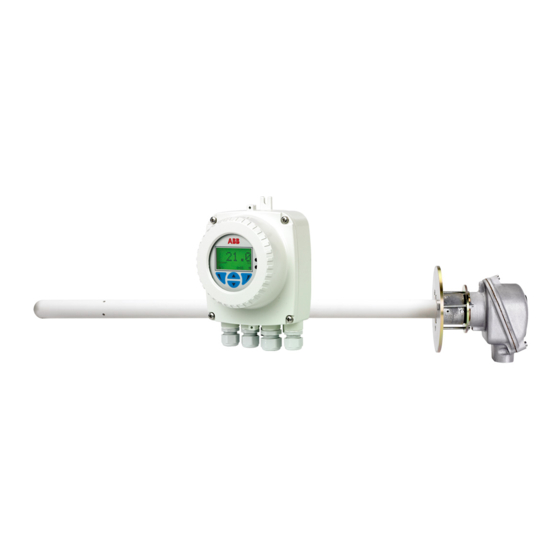
The Endura AZ20 is the latest in a long
leader in oxygen
line of high-quality, combustion gas
measurement
analyzers from ABB.
The sensor, based on a zirconium oxide
cell, is mounted at the tip of the probe
that is inserted in the flue duct. The
resulting direct, in situ measurement
provides accurate and rapid oxygen
reading for combustion control
optimization and emissions monitoring.
Measurement made easy
This User Guide is intended for use on the
following analyzer systems:
• Endura AZ10
• Endura AZ20
• Endura AZ25
For more information
Further publications for the Endura AZ series
analyzers are available for free download from:
www.abb.com/measurement
or by scanning this code:
Search for or click on
Data sheet
DS/AZ20-EN
Endura AZ20 oxygen monitor
Combustion gas analysis
Data sheet
Endura AZ25 oxygen analyzer
DS/AZ25-EN
Combustion gas analysis
Maintenance guide
Endura AZ20 series probe
IM/AZ20M-EN
Combustion oxygen monitor
User guide
Endura AZ20 series probe
IM/AZ20P-EN
Combustion oxygen monitor
User guide
Endura AZ25 series probe
OI/AZ25P-EN
Combustion oxygen monitor
Table of Contents

Related Manuals for ABB Endura AZ series


Summary of Contents for ABB Endura AZ series
- Page 1 For more information Further publications for the Endura AZ series analyzers are available for free download from: www.abb.com/measurement — or by scanning this code: A B B M E A S U R E M E N T & A N A LY T I C S | U S E R G U I D E | I M/A Z 2 0 E - E N R E V. F...
- Page 2 Refer to Section 5.4.1, page 33 Refer to Section 5.4.2, page 36 Refer to Section 5.4.3, page 44 Refer to Section 5.4.4, page 45 Display see inside back cover *xxx Interval Displayed as: Daily/ Key: Weekly/Monthly according 1. 1-Pt and 2-Pt AutoCal options displayed to selection at Frequency only if AutoCal hardware is fitted.
-
Page 3: Table Of Contents
Endura AZ series integral and remote transmitter Combustion oxygen monitor Contents Contents Safety ............................... 3 Health & Safety ........................3 Electrical Safety – CEI / IEC 61010-1:2001-2 ................3 Symbols – CEI / IEC 61010-1:2001-2 ..................3 Product Recycling Information ....................4 Product Disposal ........................ - Page 4 Endura AZ series integral and remote transmitter Combustion oxygen monitor Contents Menus ............................ 32 5.4.1 Easy Setup ........................33 5.4.2 Calibrate ........................36 5.4.3 Diagnostics ........................44 5.4.4 Device Setup ....................... 45 5.4.5 Display ......................... 48 5.4.6 Process Alarm ......................53 5.4.7 Input/Output ........................
-
Page 5: Safety
Endura AZ series integral and remote transmitter Combustion oxygen monitor 1 Safety 1 Safety Information in this manual is intended only to assist our customers in the efficient operation of our equipment. Use of this manual for any other purpose is specifically prohibited and its contents are not to be reproduced in full or part without prior approval of the Technical Publications Department. -
Page 6: Product Recycling Information
Endura AZ series integral and remote transmitter Combustion oxygen monitor 1 Safety The equipment is protected through double insulation. This symbol, when noted on a product, indicates a potential hazard which could cause serious personal injury and / or death. -
Page 7: Product Disposal
Currently, monitoring and control instruments do not fall within the scope of the RoHS Directive, however ABB has taken RoHS the decision to adopt the recommendations in the Directive as the target for all future product design and component purchasing. -
Page 8: Safety Conventions
Other than the serviceable items listed in IM/AZ20P–EN, none of the instrument's components can be serviced by the user. Only personnel from ABB or its approved representative(s) is (are) authorized to attempt repairs to the system and only components formally approved by the manufacturer should be used. -
Page 9: Introduction
2 Introduction 2 Introduction The new Endura AZ20 is the latest in a long line of high-quality, combustion gas analyzers from ABB and provides continuous monitoring of oxygen content in applications using in situ probes. Operation and programming of the Endura AZ20 is via four capacitive switches and a digital display located on the front of the transmitter. -
Page 10: Mechanical Installation
Endura AZ series integral and remote transmitter Combustion oxygen monitor 3 Mechanical Installation 3 Mechanical Installation 3.1 Unpacking Caution. Visually inspect equipment for damage before installing. Do not install damaged or faulty equipment. 3.2 End of Life Disposal The transmitter contains a small lithium battery that must be removed and disposed of responsibly in accordance with local environmental regulations. -
Page 11: Installation Conditions - Transmitter
Endura AZ series integral and remote transmitter Combustion oxygen monitor 3 Mechanical Installation 3.4 Installation Conditions – Transmitter Caution. Remote transmitter shown. Refer to IM/AZ20P–EN for integral transmitter installation conditions. 55 °C (131 °F) Max. –20 °C (–40 °F) Min. -
Page 12: Overall Dimensions
Endura AZ series integral and remote transmitter Combustion oxygen monitor 3 Mechanical Installation 3.5 Overall Dimensions 3.5.1 Remote Transmitter Dimensions Fix remote transmitter to a secure surface using 3 x M5 screws (not supplied). Dimensions in mm (ft.) 150 (5.9 ) 98 (3.9) -
Page 13: Electrical Installation
Endura AZ series integral and remote transmitter Combustion oxygen monitor 4 Electrical Installation 4 Electrical Installation 4.1 Electrical Safety Warning. The transmitter is not fitted with a switch therefore a disconnecting device such as a switch or circuit breaker conforming to local safety standards must be fitted to the final installation. It must be fitted in close proximity to the transmitter within easy reach of the operator and must be marked clearly as the disconnection device for the transmitter –... -
Page 14: Ac Power Supply Connections
Endura AZ series integral and remote transmitter Combustion oxygen monitor 4 Electrical Installation 4.1.1 AC Power Supply Connections Note. Tighten power supply terminal screws to a torque of 0.8 Nm (7 lbf.in). Fuse Line 100 to 240 V AC (±10 %) -
Page 15: Remote Transmitter - Access To Terminals
Endura AZ series integral and remote transmitter Combustion oxygen monitor 4 Electrical Installation 4.2 Remote Transmitter – Access to Terminals Warning. Isolate the transmitter from power supplies before removing the cover. Fig. 4.2 Accessing Remote Transmitter Terminals Referring to Fig. 4.2: 1. -
Page 16: Remote Transmitter - Cable Gland Entries And Main Board Connections
Endura AZ series integral and remote transmitter Combustion oxygen monitor 4 Electrical Installation 4.3 Remote Transmitter – Cable Gland Entries and Main Board Connections Anti-tamper seal Fuse Relay Terminal AC Power Probe Cable Supply Terminal Terminals Output Terminals Anti-tamper Internal Earth... -
Page 17: Remote Transmitter - Remote Az10 Sensor Cable Connections
Endura AZ series integral and remote transmitter Combustion oxygen monitor 4 Electrical Installation 4.4 Remote Transmitter – Remote AZ10 Sensor Cable Connections 4.4.1 Systems with 5 m (18 ft) Cable Length Sensor connection Transmitter Connection Cable Color Connection / Note... -
Page 18: Systems With ³5 M (³18 Ft) Cable Length
Endura AZ series integral and remote transmitter Combustion oxygen monitor 4 Electrical Installation 4.4.2 Systems with 5 m (18 ft) Cable Length Sensor connection Transmitter Connection Cable Color Connection / Note White / Yellow (not used) White / Yellow (not used) -
Page 19: Remote Transmitter - Remote Az20 Probe Cable Connections
Endura AZ series integral and remote transmitter Combustion oxygen monitor 4 Electrical Installation 4.5 Remote Transmitter – Remote AZ20 Probe Cable Connections Terminal Tag ID Connection Type Cable Color Code Number Heater Brown Heater Blue Screen Screens T / C –... -
Page 20: Remote Transmitter - Remote Az25 Probe Connections
Endura AZ series integral and remote transmitter Combustion oxygen monitor 4 Electrical Installation 4.6 Remote Transmitter – Remote AZ25 Probe Connections Transmitter Remote transmitter to probe cable Probe / remote transmitter terminal block color – wire colors connection Green Green... - Page 21 Endura AZ series integral and remote transmitter Combustion oxygen monitor 4 Electrical Installation Endura AZ25 probe T/C + Green T/C – White Cell + Cell – Black Factory-made ACJC Orange connections (at probe inner ACJC Blue terminal connectors) Screen / drain of 6-core...
-
Page 22: Remote Transmitter - Remote Az25 Autocal Unit Connections
Endura AZ series integral and remote transmitter Combustion oxygen monitor 4 Electrical Installation 4.7 Remote Transmitter – Remote AZ25 AutoCal Unit Connections Terminal Tag ID Connection Type Cable Color Code Number Not used Not used Not used Screen Screens T / C –... -
Page 23: Remote Transmitter - Power Supply And Output Connections
Endura AZ series integral and remote transmitter Combustion oxygen monitor 4 Electrical Installation 4.8 Remote Transmitter – Power Supply and Output Connections Warning. The transmitter must be earthed. Isolate the incoming mains power supply cable before making connections at the transmitter or the probe. -
Page 24: Remote Transmitter - Internal Heater Fuse Replacement
Endura AZ series integral and remote transmitter Combustion oxygen monitor 4 Electrical Installation 4.8.1 Remote Transmitter – Internal Heater Fuse Replacement Note. The internal fuse is a protection device for the probe heater – it is not a transmitter mains power isolation device. -
Page 25: Integral Transmitter - Probe Cable Connections
Endura AZ series integral and remote transmitter Combustion oxygen monitor 4 Electrical Installation 4.10 Integral Transmitter – Probe Cable Connections Terminal / Cable Color Tag ID Connection Type Blue Heater Brown Heater Screen Screen White TC – Thermocouple (–ve) Green... -
Page 26: Integral Transmitter - Power Supply And Output Connections
Endura AZ series integral and remote transmitter Combustion oxygen monitor 4 Electrical Installation 4.11 Integral Transmitter – Power Supply and Output Connections Warning. The transmitter must be earthed. Isolate the incoming mains power supply cable before making connections at the transmitter. -
Page 27: Integral Transmitter - Internal Heater Fuse Replacement
Endura AZ series integral and remote transmitter Combustion oxygen monitor 4 Electrical Installation 4.11.1 Integral Transmitter – Internal Heater Fuse Replacement Note. The internal fuse is a protection device for the probe heater – it is not an integral transmitter mains power isolation device. -
Page 28: Programming
Endura AZ series integral and remote transmitter Combustion oxygen monitor 5 Programming 5 Programming 5.1 Navigating Menus and Parameters The four keys below the display are used to navigate the menus and execute all system commands and selections. Menu Easy Setup... -
Page 29: Overview Of Operator Pages And Menus
Endura AZ series integral and remote transmitter Combustion oxygen monitor 5 Programming 5.2 Overview of Operator Pages and Menus At power-up, Operator Page 1 is displayed – this is the normal operating state of the transmitter. The Operator Menu is accessed by pressing –... -
Page 30: Operator Menu
Endura AZ series integral and remote transmitter Combustion oxygen monitor 5 Programming 5.2.2 Operator Menu The Operator Menu is used to view: Operator Menu a list of current alarms (from the Diagnostics option) Diagnostics Operator Page 1 only, Operator Page 2 only or, if... - Page 31 Endura AZ series integral and remote transmitter Combustion oxygen monitor 5 Programming Display Overview Section and Function Signals View Signals View The Signals View displays active signals and their values as a list. xx.x %O2 xx.x %O2 xxx °C ...
-
Page 32: Passwords And Security Options
Endura AZ series integral and remote transmitter Combustion oxygen monitor 5 Programming 5.3 Passwords and Security Options Passwords can be set to enable secure end-user access at two levels: Standard and Advanced. The Service level is reserved for factory use only. The Read Only level does not require password access. - Page 33 Endura AZ series integral and remote transmitter Combustion oxygen monitor 5 Programming Access Level Access Level Logout The Access Level is used to access menus at Read Only , Standard, Read Only Advanced and Service levels. Standard Advanced Service The Access Level screen is displayed by pressing...
-
Page 34: Menus
Endura AZ series integral and remote transmitter Combustion oxygen monitor 5 Programming 5.4 Menus To access menus from an Operator Page, press (beneath the icon), select an access level and enter a user password for Standard and Advanced levels. To enter Read Only level press To scroll between top level menus, press keys. -
Page 35: Easy Setup
Endura AZ series integral and remote transmitter Combustion oxygen monitor 5 Programming 5.4.1 Easy Setup The Easy Setup menu contains a series of easy setup options Menu for users with Advanced level access. Easy Setup Standard and Read Only level users cannot access the Easy Setup menu. - Page 36 Endura AZ series integral and remote transmitter Combustion oxygen monitor 5 Programming Parameter Comment / [Range] Default …Easy Setup Cable Length The length in metres of the cable between the probe and the remote transmitter. This length is used in the cold junction measurement to compensate for the impedance of the cable.
- Page 37 Endura AZ series integral and remote transmitter Combustion oxygen monitor 5 Programming Parameter Comment / [Range] Default …Easy Setup Temperature Units Selects the units to be used for all temperature values in the transmitter. °C °C °F Factory Cal. Offset Used to enter the calibration offset value supplied with the new probe / cell.
-
Page 38: Calibrate
Endura AZ series integral and remote transmitter Combustion oxygen monitor 5 Programming 5.4.2 Calibrate Used to calibrate the sensor, select test gas types, set oxygen Menu hold action, enable automatic calibration hardware (if fitted) Calibrate and set calibration diagnostics options. - Page 39 Endura AZ series integral and remote transmitter Combustion oxygen monitor 5 Programming Parameter Comment / [Range] Default …Calibrate Test Gases Configures the test gas types and values used in calibration. Test Gas 1 Type Enables the Test Gas 1 Value option.
- Page 40 Endura AZ series integral and remote transmitter Combustion oxygen monitor 5 Programming Parameter Comment / [Range] Default …Calibrate AutoCal Hardware Selects the type of automatic calibration hardware to be used. Hardware Type None None Disables automatic calibration functions. Internal Enabled if the (optional) built-in automatic calibration is fitted.
- Page 41 Endura AZ series integral and remote transmitter Combustion oxygen monitor 5 Programming Parameter Comment / [Range] Default …Calibrate …AutoCal Hardware Selects the type of automatic calibration hardware to be used. Valve Manual Control The automatic calibration solenoid valves can be energised manually.
- Page 42 Endura AZ series integral and remote transmitter Combustion oxygen monitor 5 Programming Parameter Comment / [Range] Default …Calibrate …Scheduled Cal. If AutoCal is fitted, calibrations can be set to run automatically at scheduled time intervals. Note. This option is not available if the AutoCal Hardware / Hardware Type is set to None.
- Page 43 Endura AZ series integral and remote transmitter Combustion oxygen monitor 5 Programming Parameter Comment / [Range] Default …Calibrate …Scheduled Cal. If AutoCal is fitted, calibrations can be set to run automatically at scheduled time intervals. Note. This option is not available if the AutoCal Hardware / Hardware Type is set to None.
- Page 44 Endura AZ series integral and remote transmitter Combustion oxygen monitor 5 Programming Parameter Comment / [Range] Default …Calibrate Cal. Diagnostics Cal. Overdue Diag. A diagnostic warning can be generated to advise when a calibration is due. Weeks [1, 2, 3 or 4]...
- Page 45 Endura AZ series integral and remote transmitter Combustion oxygen monitor 5 Programming Parameter Comment / [Range] Default …Calibrate …Cal. Diagnostics …Cell Diagnostics Slow Recovery Warns if the probe's recovery rate is slower than Diag. expected after a calibration or accuracy check is measured.
-
Page 46: Diagnostics
Endura AZ series integral and remote transmitter Combustion oxygen monitor 5 Programming 5.4.3 Diagnostics Used to view diagnostic and performance (historical) data and Menu review cell diagnostics – see Section 8.1, page 78. Diagnostics Note. Diagnostics messages listed at this level do not include troubleshooting tips. -
Page 47: Device Setup
Endura AZ series integral and remote transmitter Combustion oxygen monitor 5 Programming 5.4.4 Device Setup Used by Advanced users to set the instrument tag, specify the Menu type of probe, select cable length, set oxygen and Device Setup temperature ranges and to setup passwords for access at all levels. - Page 48 Endura AZ series integral and remote transmitter Combustion oxygen monitor 5 Programming Parameter Comment / [Range] Default …Device Setup Oxygen Setup %O2 Range Hi 25.00 %O Sets the maximum oxygen concentration [0.01 to 100 % O %O2 Range Lo 0.01 %O Sets the minimum oxygen concentration [0.01 to 100 % O...
- Page 49 Endura AZ series integral and remote transmitter Combustion oxygen monitor 5 Programming Parameter Comment / [Range] Default …Device Setup Security Setup Used to set Standard and Advanced level passwords of None up to 6 alphanumeric characters. Note. Standard and Advanced passwords are not set at the factory and must be added by the end-user(s).
-
Page 50: Display
Endura AZ series integral and remote transmitter Combustion oxygen monitor 5 Programming 5.4.5 Display Used to set the Display Mode (lines of information displayed Menu on the Operator Pages), enable or disable Autoscroll, set the Display time and date and time and date format, select a Daylight Saving region and adjust the screen contrast. - Page 51 Endura AZ series integral and remote transmitter Combustion oxygen monitor 5 Programming Parameter Comment / [Range] Default …Display …Operator Page 1 1st Line View % Oxygen % Oxygen 2nd Line View Cell Temperature Cell Temperature Cell Millivolts Control Output 3rd Line View...
- Page 52 Endura AZ series integral and remote transmitter Combustion oxygen monitor 5 Programming Parameter Comment / [Range] Default …Display Operator Page 2 Specifies the type of information to be displayed on each (text) line. Display Mode Selects the number of lines of information and maximum number of characters per line displayed on the selected Operator page.
- Page 53 Endura AZ series integral and remote transmitter Combustion oxygen monitor 5 Programming Parameter Comment / [Range] Default …Display …Operator Page 2 3rd Line View % Oxygen Cell Temperature Cell Millivolts Cell Millivolts Control Output Bargraph Specifies the parameter represented on the bargraph.
- Page 54 Endura AZ series integral and remote transmitter Combustion oxygen monitor 5 Programming Parameter Comment / [Range] Default …Display Daylight Saving Sets the geographical region and daylight saving start / end times, occurrences and dates. Region Daylight saving is disabled. Europe Standard daylight saving start- and end-times are selected automatically for Europe.
-
Page 55: Process Alarm
Endura AZ series integral and remote transmitter Combustion oxygen monitor 5 Programming 5.4.6 Process Alarm Used to setup process alarms (1 to 4) for alarm types (high / Menu low oxygen or high / low temperature), set alarm trip Process Alarm temperatures and to set hysteresis values (as % for oxygen and °... -
Page 56: Input/Output
Endura AZ series integral and remote transmitter Combustion oxygen monitor 5 Programming 5.4.7 Input/Output Used to assign relays (1 and 2), digital I/O (1 and 2) and Menu current outputs (1 and 2). Input/Output Menus displayed at this level are dependent on the system configuration / options fitted. - Page 57 Endura AZ series integral and remote transmitter Combustion oxygen monitor 5 Programming Parameter Comment / [Range] Default …Input/Output Relay 1 (2) Polarity Selects whether the relay contacts are closed or open if any of the Relay Assignment options are active (Assigned).
- Page 58 Endura AZ series integral and remote transmitter Combustion oxygen monitor 5 Programming Parameter Comment / [Range] Default …Input/Output …Digital I/O 1 (2) …Output Assignment Diag. – Failure Activates the output if a Failure diagnostic status is generated – see Section 8.1, page 78.
- Page 59 Endura AZ series integral and remote transmitter Combustion oxygen monitor 5 Programming Parameter Comment / [Range] Default …Input/Output …Digital I/O 1 (2) Type Selects the type of automatic calibrations started by a digital input – see Section 6.1, page 64.
- Page 60 Endura AZ series integral and remote transmitter Combustion oxygen monitor 5 Programming Parameter Comment / [Range] Default …Input/Output Current Output 1 Source Selects the parameter to be retransmitted by the current output. % Oxygen % Oxygen Temperature Cell mV Type Selects a linear or logarithmic output.
- Page 61 Endura AZ series integral and remote transmitter Combustion oxygen monitor 5 Programming Parameter Comment / [Range] Default …Input/Output …Current Output 1 Elec. Range Hi Selects the electrical range high current output value. [3.80 to 22.00 mA] 20.00 mA Elec. Range Lo Selects the electrical range low current output value.
- Page 62 Endura AZ series integral and remote transmitter Combustion oxygen monitor 5 Programming Parameter Comment / [Range] Default …Input/Output Current Output 2 Displayed only if an option board is fitted. Elec. Range Hi Selects the electrical range high current output value.
-
Page 63: Communication
Endura AZ series integral and remote transmitter Combustion oxygen monitor 5 Programming 5.4.8 Communication Used to configure HART communication parameters and Menu cyclic output communication via the IrDA interface on the front Communication of the transmitter. Select Exit Parameter Comment / [Range]... - Page 64 Endura AZ series integral and remote transmitter Combustion oxygen monitor 5 Programming Parameter Comment / [Range] Default …Communication Cyclic Output For diagnostic purposes, it is possible to configure the device (transmitter) to send out data values via the IrDA interface on the front of the transmitter – these can be viewed via hyperterminal.
-
Page 65: Device Info
Endura AZ series integral and remote transmitter Combustion oxygen monitor 5 Programming 5.4.9 Device Info Identifies the transmitter’s serial number, transmitter’s date of Menu manufacture, the last oxygen calibration date, the probe type, Device Info the transmitter options card (if fitted), AutoCal hardware (if fitted) and main board and software version numbers. -
Page 66: Calibration
Endura AZ series integral and remote transmitter Combustion oxygen monitor 6 Calibration 6 Calibration Caution. Set up the test gas and reference air supplies before running a calibration – see IM/AZ20P-EN. 6.1 Overview of Calibration Procedures Procedure Calibration Type and Description... -
Page 67: Calibrating The System
Endura AZ series integral and remote transmitter Combustion oxygen monitor 6 Calibration 6.2 Calibrating the System The calibration routines applicable to calibration types are identified in the right column of the following table: Start automatic calibration1-Pt AutoCal Back •... -
Page 68
Endura AZ series integral and remote transmitter Combustion oxygen monitor 6 Calibration …Calibration Procedures Waiting for Application of Test Gas (2 Point)
Note. The test gas used for this stage of the calibration is always Test Connect Test Gas 2 Gas 2. -
Page 69
Endura AZ series integral and remote transmitter Combustion oxygen monitor 6 Calibration …Calibration Procedures Calibration completed successfully
1.00 %O2 Cal Offset 0.00 mV Cal Factor 1.000 Reject Accept • New calibration • New calibration coefficients saved coefficients discarded Save successful •... -
Page 70: Hart -Protocol
Hand-held Terminal The transmitter can be accessed and configured using a compatible hand-held terminal (such as the ABB Mobility DHH801-MFC or equivalent – see Fig. 7.1, page 69). Transmitter connection is made in parallel with the 4 to 20 mA current output –... -
Page 71: Hart-Protocol Connection
Endura AZ series integral and remote transmitter Combustion oxygen monitor 7 HART®-Protocol 7.2 HART-Protocol Connection Fig. 7.1 shows HART-Protocol connection details for transmitter installations. Note. Current output connection details are common for both remote and integral transmitters. The HART-Protocol is also available optically via the IrDA interface on the front of the transmitter. -
Page 72: Hart Universal Commands Set
Endura AZ series integral and remote transmitter Combustion oxygen monitor 7 HART®-Protocol 7.3 HART Universal Commands Set Command Description Details Read Transmitter Expanded device type code. Unique Identifier Manufacturer identification code. Manufacturer device type code. Number of preambles. Revision level of HART Universal Command set implemented. - Page 73 Endura AZ series integral and remote transmitter Combustion oxygen monitor 7 HART®-Protocol Command Description Details Read Message Returns the user-defined HART message. Message can also be viewed via Communications menu on the transmitter's local HMI. Read Tag, Descriptor Returns the user-defined HART information:...
-
Page 74: Hart Common Practice Command Set
Endura AZ series integral and remote transmitter Combustion oxygen monitor 7 HART®-Protocol 7.4 HART Common Practice Command Set Command Description Details Read Transmitter Up to 4 slots. Each slot can be programmed to return the Variables following parameters based on the Transmitter Variable... - Page 75 Endura AZ series integral and remote transmitter Combustion oxygen monitor 7 HART®-Protocol Command Description Details Trim Primary Variable The transmitter re-calibrates the current output Zero Offset Current DAC Zero based on the externally measured primary value received. Trim Primary Variable...
-
Page 76: Device Status Information
Endura AZ series integral and remote transmitter Combustion oxygen monitor 7 HART®-Protocol 7.5 Device Status Information 7.5.1 Field Device Status First Byte First Bit is set to 1 Description Bit #7 Set to 1 = communications error Bit #6 Vertical parity error... -
Page 77: Field Device Status Second Byte
Endura AZ series integral and remote transmitter Combustion oxygen monitor 7 HART®-Protocol 7.5.2 Field Device Status Second Byte Second Byte Description Bit #7 Field Device Malfunction A hardware error or failure has been detected by the device. Further information may be available through the Read Additional Transmitter Status command. -
Page 78: Additional Transmitter Status Information - Command 48
Endura AZ series integral and remote transmitter Combustion oxygen monitor 7 HART®-Protocol 7.5.3 Additional Transmitter Status Information – Command 48 Byte 0 Description Bit #7 Probe O sensor broken Bit #6 ADC failure Bit #5 SV (Temperature) out of range... - Page 79 Endura AZ series integral and remote transmitter Combustion oxygen monitor 7 HART®-Protocol Byte 3 Description Bit #7 Cell offset approaching limit Bit #6 Cell factor approaching limit Bit #5 Accuracy check stability failure Bit #4 Calibration stability failure Bit #3...
-
Page 80: Troubleshooting
Endura AZ series integral and remote transmitter Combustion oxygen monitor 8 Troubleshooting 8 Troubleshooting 8.1 Diagnostics Classification Codes Diagnostic messages and icons conforming to the NAMUR NE107 classification code are used to define information during operation and data entry – a typical diagnostic message is shown in Fig. 8.1: Process - - F070. -
Page 81: Diagnostics Messages
Endura AZ series integral and remote transmitter Combustion oxygen monitor 8 Troubleshooting 8.2 Diagnostics Messages Note. Diagnostics messages are listed in order of highest priority. 8.2.1 Failure Messages Message range: F100.000 to F070.003. Status Diagnostic Possible Cause(s) Corrective Measure(s) Icon Message ––F100.000––... - Page 82 Endura AZ series integral and remote transmitter Combustion oxygen monitor 8 Troubleshooting Status Diagnostic Possible Cause(s) Corrective Measure(s) Icon Message ––F088.009–– THERMOCOUPLE Thermocouple wired incorrectly. Correct wiring. REVERSED Correct wiring ––F086.010–– Check wiring. COLD JUNCTION FAILED Replace cold junction sensor.
- Page 83 Endura AZ series integral and remote transmitter Combustion oxygen monitor 8 Troubleshooting Status Diagnostic Possible Cause(s) Corrective Measure(s) Icon Message ––F076.047–– INTERNAL COMMS Switch power to transmitter off and ERROR then on again. Temporary or permanent hardware Cycle power. If failure.
-
Page 84: Out Of Specification Messages
Endura AZ series integral and remote transmitter Combustion oxygen monitor 8 Troubleshooting 8.2.2 Out of Specification Messages Message range: S068.040 to S048.005 Status Diagnostic Message Possible Cause(s) Corrective Measure(s) Icon Displayed ––S068.040–– Modify ambient temperature. INTERNAL TEMP. Replace cartridge. Ambient temperature too high / OUT OF RANGE low or fault in electronics. - Page 85 Endura AZ series integral and remote transmitter Combustion oxygen monitor 8 Troubleshooting Status Diagnostic Message Possible Cause(s) Corrective Measure(s) Icon Displayed ––S054.011–– CELL WARMING UP Cell temperature is below 690 °C Wait for cell temperature to reach Wait for cell (1274 °F).
-
Page 86: Maintenance Messages
Endura AZ series integral and remote transmitter Combustion oxygen monitor 8 Troubleshooting 8.2.3 Maintenance Messages Message range: M042.029 to M022.020 Status Diagnostic Message Possible Cause(s) Corrective Measure(s) Icon Displayed ––M042.029–– Check gas connections. ACCURACY CHECK STABILITY FAILED Cell input measurement is too Repeat accuracy check. - Page 87 Endura AZ series integral and remote transmitter Combustion oxygen monitor 8 Troubleshooting Status Diagnostic Message Possible Cause(s) Corrective Measure(s) Icon Displayed ––M030.021–– TEST GAS 1 NOT Check test gas lines. Test gas cylinder empty. PRESENT Replace test gas cylinder. Check test gas ––M028.022––...
-
Page 88: Check Function Messages
Endura AZ series integral and remote transmitter Combustion oxygen monitor 8 Troubleshooting 8.2.4 Check Function Messages Message range: C020.041 to M002.0XX Status Diagnostic Message Possible Cause(s) Corrective Measure(s) Icon Displayed ––C020.041–– SIMULATION MODE Exit simulation mode before using in Transmitter is in simulation mode. - Page 89 Endura AZ series integral and remote transmitter Combustion oxygen monitor 8 Troubleshooting Status Diagnostic Message Possible Cause(s) Corrective Measure(s) Icon Displayed ––C012.023–– TEST GAS VALVES IN TEST MODE Calibration in progress. No action required. Valves under manual control. No action req'd ––C010.024––...
-
Page 90: Performance Log
Endura AZ series integral and remote transmitter Combustion oxygen monitor 8 Troubleshooting 8.3 Performance Log 8.3.1 Log Entries Information displayed in the Performance Log is derived from the values obtained during calibration routines. When the Performance Log is selected, an icon ( in Fig. -
Page 91: Performance Log Codes
Endura AZ series integral and remote transmitter Combustion oxygen monitor 8 Troubleshooting 8.3.2 Performance Log Codes Parameter Comment / Range Type The calibration type, represented as an icon – see Table 8.6, page 88: Calibration Failed Cal ... - Page 92 Endura AZ series integral and remote transmitter Combustion oxygen monitor 8 Troubleshooting Parameter Comment / Range Recovery Rate Calibration / The maximum recorded rate of change of the calculated oxygen value when the Accuracy Check test gas is removed and the measurement returns to the process value.
-
Page 93: Remote Computer Connection
9 Remote Computer Connection 9 Remote Computer Connection 9.1 Utility Software for PC When communication between the device and a remote PC is made (using the IrDA adaptor and ABB Service Port Switch software) ABB Utility Software enables: cyclic data and parameter data to be downloaded and saved to a compatible spreadsheet application such as Excel –... -
Page 94: Connecting The Irda Port
Endura AZ series integral and remote transmitter Combustion oxygen monitor 9 Remote Computer Connection 9.3 Connecting the IrDA Port Note. The IrDa port is functional only when the Cyclic Output Interval parameter (see Section 5.4.8, page 62) is not set to 'Off'. -
Page 95: Cyclic Data
Endura AZ series integral and remote transmitter Combustion oxygen monitor 9 Remote Computer Connection 9.5 Cyclic Data Cyclic data can be saved and output to a spreadsheet or as text. The update rate and data groups enabled for output are selected at the Communication / Cyclic Output menu. -
Page 96: Remote Hmi (Human Machine Interface)
HMI. 9.8 HART Client Note. Any standard HART application can be used via the infrared interface and the ABB Service Port Switch. All communications are handled automatically with no need for a HART modem. -
Page 97: Spares And Accessories
10.1 Documentation & Software Part No. Description IM/AZ20M–EN Maintenance Guide Download* the guide from: www.ABB.com/analytical-instruments AZ20 DTM Software Device Type Manager – please contact ABB for details 10.2 Transmitter Spares Part No. Description AZ20 Transmitter Cartridge AZ200 750 Standard AZ200 751... -
Page 98: System Specification
Endura AZ series integral and remote transmitter Combustion oxygen monitor 11 System Specification 11 System Specification Measurement Performance Power Supply Range – AZ20 AC power supply 0.01 to 100 % O 100 to 240 V AC ±10 % (90 V min. to 264 V max.) 50 / 60 Hz Range –... -
Page 99: Transmitter Specification
Endura AZ series integral and remote transmitter Combustion oxygen monitor 12 Transmitter Specification 12 Transmitter Specification Transmitter enclosures Relay outputs Remote Number Wall-, pipe- or stand-mounted 2 standard 4 gland entries Type Optional in NPT, M20 Normally closed 5 A @ 230 V AC or 30 V DC (non-inductive) - Page 100 Endura AZ series integral and remote transmitter Combustion oxygen monitor 12 Transmitter Specification Digital inputs/outputs Infrared service port Number Accessibility 2 (optional) Through front face Type Type User-configurable as either input or output IrDA standard Input Baud rate Volt-free contact...
- Page 101 Refer to Section 5.4.5, page 48 Refer to Section 5.4.6, page 53 Refer to Section 5.4.7, page 54 Refer to Section 5.4.8, page 61 Refer to Section 5.4.9, page 63 Diagnostics To first from inside available front cover menu AZ10 With Filter AZ10 No Filter Key: 4.
- Page 102 We reserve all rights in this document and in the subject matter and illustrations Sales Service Software contained therein. Any reproduction, disclosure to third parties or utilization of its contents – in whole or in parts – is forbidden without prior written consent of ABB. Copyright© ABB 2018 All rights reserved...