Table of Contents
Quick Links
Table of Contents

Related Manuals for Emerson SI-EtherCAT


Summary of Contents for Emerson SI-EtherCAT
- Page 1 User Guide SI-EtherCAT Part Number: 0478-0152-02 Issue Number: 2...
- Page 2 The information contained in this guide is for guidance only and does not form part of any contract. The accuracy cannot be guaranteed as Emerson have an ongoing process of development and reserve the right to change the specification of their products without notice.
-
Page 3: Table Of Contents
Conventions used in this guide ................9 Mechanical installation ................10 General installation ....................10 Electrical installation .................13 SI-EtherCAT module information ................13 SI-EtherCAT terminal descriptions ................ 14 Module grounding and EMC .................. 14 Network topology ....................15 Minimum node-to-node cable length ..............15 Getting started ...................16... - Page 4 Parameter type codes ....................82 Single line parameter descriptions .................83 Full parameter descriptions ..................85 Diagnostics ....................94 10.1 Module identification parameters ................94 10.2 SI-EtherCAT module temperature ................94 10.3 Error handling ......................94 10.4 Drive trip display codes ..................96 10.5 Option module trips ....................97 10.6...
-
Page 5: Safety Information
The Safe Torque Off function may be used in a safety-related application. The system designer is responsible for ensuring that the complete system is safe and designed correctly according to the relevant safety standards. SI-EtherCAT User Guide Issue Number: 2... -
Page 6: Environmental Limits
The drive contains capacitors that remain charged to a potentially lethal voltage after the AC supply has been disconnected. If the drive has been energized, the AC supply must be isolated at least ten minutes before work may continue. SI-EtherCAT User Guide Issue Number: 2... -
Page 7: Introduction
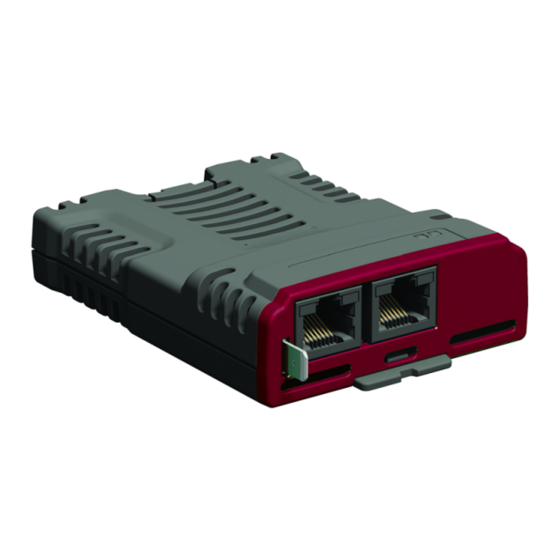
This User Guide covers the SI-EtherCAT option module .Both the SI-Ethernet module and the onboard Ethernet interface offer the same functionality. The SI-EtherCAT is an option module that provides EtherCAT connectivity and can be installed to the following drives: •... -
Page 8: Option Module Identification
Example: A date code of W31 would correspond to week 31 of year 2013. Product Conformance Certificate SI-EtherCAT has been awarded full EtherCAT Conformance Certification by the EtherCAT Technology Group (ETG). A copy of the certificate is available on request from your supplier or local Control Techniques Drive Centre. -
Page 9: Conventions Used In This Guide
Pr MM.ppp - Where MM signifies the menu allocated to the option module setup menu and ppp signifies the parameter number within the set-up menu. • Pr mm.000 - Signifies parameter number 000 in any drive menu. SI-EtherCAT User Guide Issue Number: 2... -
Page 10: Mechanical Installation
Option modules can only be installed on drives that have the option module slot NOTE functionality. SI-EtherCAT User Guide Issue Number: 2... - Page 11 Place the option module onto the drive as shown in (2) until the module clicks into place. The terminal cover on the drive holds the option module in place, so this must be put back on. SI-EtherCAT User Guide Issue Number: 2...
- Page 12 (A). • Press down on the option module until it clicks into place. Option module slots must be used in the following order: Slot 3 (lower), Slot 2 (middle) NOTE and then Slot 1(upper). SI-EtherCAT User Guide Issue Number: 2...
-
Page 13: Electrical Installation
EtherCAT module has two 100BASE-TX Ethernet ports, which support segment lengths of up to 100 m. This means that the maximum cable length which can be used between one SI-EtherCAT port and another 100BASE-TX port is 100 m however it is not recommended that the full 100 m cable length is used. -
Page 14: Si-Ethercat Terminal Descriptions
Not used Module grounding and EMC SI-EtherCAT is supplied with a grounding tab on the module that should be connected to the closest possible grounding point using the minimum length of cable. This will greatly improve the noise immunity of the module. -
Page 15: Network Topology
Control Techniques recommend implementing daisy chaining on EtherCAT networks (see Figure 4- 2). Other Ethernet network topologies can be used but care must be taken to ensure that the system still operates within the constraints specified by the designer. Figure 4-2 SI-EtherCAT daisy chain network topology Unidrive Unidrive... -
Page 16: Getting Started
To check that the ethernet cable connected to the SI-EtherCAT module on the drive is connected correctly, look at the LED on the front of the SI-EtherCAT module relating to the connector being used, if this light is a solid green color then a link is established with the master, if this light if off then check the cabling and also check that the master has started communications. - Page 17 5 and 6, the TxPDOs available are 1, 2, 3, 5 and 6 (for more information on these PDOs including default mappings please see section 6.3.2 RxPDO mappings on page 30 and section 6.3.3 TxPDO mappings on page 34). Figure 5-1 SI-EtherCAT PDO configuration RxPDO1 0x6040 0x6042 Pr 20.21...
- Page 18 3 PDO assignment (TxPDO) are required to assign PDOs to the synchronization task. For the purpose of the example assign one RxPDO to sync manager 2 and one TxPDOs to sync manager 3. Figure 5-2 SI-EtherCAT sync manager configuration 0x1C12 RxPDO1...
- Page 19 Download the configuration to the master. After downloading the configuration to the master the LED(s) on the front of the SI-EtherCAT should flash, depending on the port(s) connected. Values written to parameters over RxPDOs should now be viewable using the drive’s keypad so long as the master has put the slave into the operational state;...
-
Page 20: Quick Start Flowchart
START Ensure the Control Techniques .xml file is in the appropriate folder on the hard drive of the master Check the LED status of the SI-EtherCAT module In the master, scan the EtherCAT network Select required PDOs Configure the PDOs with the mappings... -
Page 21: Supported Objects
Supported objects Table 5-3 lists the objects currently supported by SI-EtherCAT Table 5-3 SI-EtherCAT Object Dictionary Profile Data Type Object Ref. Description (0x) Sub-index Type 1000 Device type UDINT 1001 Error register USINT Identity object USINT (Number of last sub-index) - Page 22 UINT (Assigned PDO index) SM3 PDO assignment USINT (Number of PDOs) 1C13 SM3 PDO assignment UINT (Assigned PDO index) SM4 PDO assignment USINT (Number of PDOs) 1C14 SM4 PDO assignment UINT (Assigned PDO index) SI-EtherCAT User Guide Issue Number: 2...
- Page 23 (Number of last sub-index) In cyclic data configuration 3007 USINT (Copy from drive task) In cyclic data configuration USINT (Copy to master task) 3008 Activate velocity mode redirection USINT 603F Error code UINT 6040 Control word UINT SI-EtherCAT User Guide Issue Number: 2...
- Page 24 UDINT (Delta speed value (rpm)) vl_velocity_ quick_stop UINT (Delta time value (s)) vl_setpoint_factor USINT (Number of last sub-index) vl_setpoint_factor 604B (Numerator) vl_setpoint_factor (Denominator) vl_dimension_factor USINT (Number of last sub-index) vl_dimension_factor 604C (Numerator) vl_dimension_factor (Denominator) SI-EtherCAT User Guide Issue Number: 2...
- Page 25 USINT (Number of last sub-index) Gear ratio 6091 UDINT (Motor revolutions) Gear ratio UDINT (Shaft revolutions) Feed constant USINT (Number of last sub-index) Feed constant 6092 UDINT (Feed value) Feed constant UDINT (Shaft revolutions) SI-EtherCAT User Guide Issue Number: 2...
- Page 26 Position control parameter set USINT (Number of last sub-index) Position control parameter set 60FB DINT (Proportional gain) Position control parameter set DINT (Speed feed forward gain) 60FF Target velocity DINT 6502 Supported drive modes UDINT SI-EtherCAT User Guide Issue Number: 2...
-
Page 27: Protocols
16 (hexadecimal), so care must be taken to enter the correct parameter number. All other supported entries in the SI-EtherCAT object dictionary can also be accessed using SDOs. Refer to the master controller documentation for full details about implementing SDO transfers within the particular master controller. -
Page 28: Canopen Over Ethercat (Coe)
Access:Range: Size: Unit: Default: Type: Description: Definitions: • : A signed 16-bit number. This is the index of the object dictionary entry specified in four hexadecimal characters. SI-EtherCAT User Guide Issue Number: 2... - Page 29 RFC-A or Regen modes or on Unidrive M200 - M400, bit 16 will be set, while bit 17 will be clear. On Unidrive M600 and above in RFC-S mode, bit 17 will be set, while bit 16 will be clear. SI-EtherCAT User Guide Issue Number: 2...
- Page 30 The RxPDO mapping objects are defined in the following tables. Each mapping object has the maximum number of sub-indices (each representing an object mapped to a PDO) defined in the XML configuration file (specified as “CF” in the following descriptions). SI-EtherCAT User Guide Issue Number: 2...
- Page 31 Bits 0 to 7: Length of the mapped object in bits, e.g. a 32-bit parameter would have a length Description: of 32 or 0x20. Bits 8 to 15: Sub-index of the mapped object. Bits 16 to 31: Index of the mapped object. SI-EtherCAT User Guide Issue Number: 2...
- Page 32 Bits 0 to 7: Length of the mapped object in bits (if a gap, bit length of the gap). Bits 8 to 15: Sub-index of the mapped object (if a gap, zero). Bits 16 to 31: Index of the mapped object (if a gap, zero). SI-EtherCAT User Guide Issue Number: 2...
- Page 33 Bits 0 to 7: Length of the mapped object in bits (if a gap is required, bit length of the gap). Description: Bits 8 to 15: Sub-index of the mapped object (if a gap, zero). Bits 16 to 31: Index of the mapped object (if a gap, zero). SI-EtherCAT User Guide Issue Number: 2...
- Page 34 Bits 0 to 7: Length of the mapped object in bits, e.g. a 32-bit parameter would have a length of Description: 32 or 0x20. Bits 8 to 15: Sub-index of the mapped object. Bits 16 to 31: Index of the mapped object. SI-EtherCAT User Guide Issue Number: 2...
- Page 35 Bits 0 to 7: Length of the mapped object in bits, e.g. a 32-bit parameter would have a length of Description: 32 or 0x20. Bits 8 to 15: Sub-index of the mapped object. Bits 16 to 31: Index of the mapped object. SI-EtherCAT User Guide Issue Number: 2...
- Page 36 Bits 0 to 7: Length of the mapped object in bits, e.g. a 32-bit parameter would have a length of Description: 32 or 0x20. Bits 8 to 15: Sub-index of the mapped object. Bits 16 to 31: Index of the mapped object. SI-EtherCAT User Guide Issue Number: 2...
- Page 37 Bits 0 to 7: Length of the mapped object in bits (if a gap is required, bit length of the gap). Bits 8 to 15: Sub-index of the mapped object (if a gap, zero). Bits 16 to 31: Index of the mapped object (if a gap, zero). SI-EtherCAT User Guide Issue Number: 2...
- Page 38 Sync manager 0 PDO assignment Sub-index 0 Access: RO Range: N/A Size: 1 byte Unit: N/A Default: Type: USINT Number of assigned PDOs. The mailbox received sync manager can never have PDOs Description: assigned to it. SI-EtherCAT User Guide Issue Number: 2...
- Page 39 Sub-index 1 to (sub-index 0) Access: RW Range: 0x1A00 to 0x1BFF Size: 2 bytes Unit: N/A Default: Type: UINT Description: The object index of a RxPDO to assign to this sync manager. SI-EtherCAT User Guide Issue Number: 2...
- Page 40 "Sync Task Orun" trip may be seen. The value of objects 0x3000 will be ignored on drives which do not support position NOTE feedback. SI-EtherCAT User Guide Issue Number: 2...
-
Page 41: Additional Position Loop Scaling
Type: DINT Description: The additional position loop output scaling numerator Sub-index 2 Access: RW Size: 4 bytes Unit: N/A Range: -2 to +2 Default: Type: DINT Description: The additional position loop output scaling denominator SI-EtherCAT User Guide Issue Number: 2... -
Page 42: Cyclic Data Loss Behaviour
Provides an indication of the number of PDO’s lost. The counter is reset when the EtherCAT network is restarted. In the event of the cyclic data not being detected within the synchronisation cycle the NOTE drive will indicate a 'PDOs Lost' alarm. SI-EtherCAT User Guide Issue Number: 2... -
Page 43: Drive Profile (Cia402) Support
Drive profile (CiA402) support SI-EtherCAT supports the following modes of the CiA402 profile: • Homing Mode • Cyclic Synchronous Position Mode • Interpolated Position Mode • vl velocity mode • Cyclic Synchronous Velocity Mode • Cyclic Synchronous Torque Mode 0x6040 Controlword This provides the primary method of controlling the behavior of the drive e.g. -
Page 44: 0X6041 Statusword
SI-EtherCAT User Guide Issue Number: 2... -
Page 45: Common Profile Features
The SI-EtherCAT master device must be in the operational state before the state machine can move from the ‘SWITCH ON DISABLED’ state to the ‘READY TO SWITCH ON’ state. If the master leaves the operational state while the state machine is in the ‘SWITCH ON’, ‘OPERATION... - Page 46 Profile SW& 0xFF90 | 0x0027 Set drive run state Quick Stop Start quick stop Enable operation (mode specific ) Quick Stop Active Profile SW& 0xFF90 | 0x0007 Drive stopped? Stay in Quick Stop state? SI-EtherCAT User Guide Issue Number: 2...
- Page 47 Enable operation command from control device, if the quick stop option code is 5, 6, 7 The drive function shall be enabled or 8 SI-EtherCAT User Guide Issue Number: 2...
- Page 48 Size: Unsigned 16 Unit: N/A Default: Type: UINT This object is used to control what action is performed if there is a transition from the Description: Operation Enabled state to the Switched On state. SI-EtherCAT User Guide Issue Number: 2...
- Page 49 2. In RFC-s the default is 8. Table 7-17 Modes_of_operation values Value Definition No mode change vl velocity mode Homing mode Interpolated Position mode Cyclic Sync Position mode Cyclic Sync Velocity mode Cyclic Sync Torque mode SI-EtherCAT User Guide Issue Number: 2...
- Page 50 Quick stop function for the positioning related modes. 7.3.10 Profile units The SI-EtherCAT implementation provides a means to convert profile units into position controller and drive units. All scaling values are standard profile objects. The following objects are supported: Table 7-22 Supported profile units...
- Page 51 Range: 0 to 0xFFFFFFFF Size: Unsigned 32 Unit: N/A Default: Type: UDINT Description: Encoder increments Sub-index 2 Access: RO Range: 0 to 0xFFFFFFFF Size: Unsigned 32 Unit: N/A Default: Type: UDINT Description: Motor revolutions SI-EtherCAT User Guide Issue Number: 2...
- Page 52 Access: RW Range: 0 to 0xFFFFFFFF Size: Unsigned 32 Unit: N/A Default: Type: UDINT Description: Feed Sub-index 2 Access: RW Range: 0 to 0xFFFFFFFF Size: Unsigned 32 Unit: N/A Default: Type: UDINT Description: Shaft revolutions SI-EtherCAT User Guide Issue Number: 2...
- Page 53 Table 7-29 Following error window 0x6065 Following error window Sub-index 0 Range: Range: 0 to Access: RW Size: 4 bytes Unit: N/A 0xFFFFFFFF Default: 0xFFFFFFFF Type: UDINT Description: Permitted range of position values before a following error occurs. SI-EtherCAT User Guide Issue Number: 2...
- Page 54 Table 7-33 Following_error actual_value 0x60F4 Following_error actual_value Sub-index 0 Access: RO Range: 0 to 0xFFFFFFFF Size: signed 32 Unit: N/A Default: Type: DINT Description: This read only object provides the actual value of the following error. SI-EtherCAT User Guide Issue Number: 2...
- Page 55 The position_demand_value object contains the value supplied by either the interpolated position mode or the profile position mode (in user units). It is updated every control loop cycle. This object can be mapped as cyclic data. SI-EtherCAT User Guide Issue Number: 2...
-
Page 56: Interpolated Position Mode
0x60C1 interpolation_data_record 0x60C2 interpolation_time_period When using one of the CiA402 positioning modes, Distributed Clocks must be enabled. NOTE Failure to do so may result in the SI-EtherCAT module going into the SAFE- OPERATIONAL state. SI-EtherCAT User Guide Issue Number: 2... - Page 57 The implementation of interpolated position mode allows synchronous operation only, where a fixed, common interpolation interval is defined. The time specified must always be an integer multiple of the control loop cycle time. The time period index has a minimum value of -6 (i.e. the SI-EtherCAT User Guide Issue Number: 2...
-
Page 58: Vl Velocity Mode
Table 7-41 vl velocity mode supported objects Index Name 0x3008 Active velocity mode redirection 0x6042 vl_target_velocity 0x6043 vl_velocity_demand 0x6044 vl_velocity_actual_value 0x6046 vl_velocity_min_max_amount 0x6048 vl_velocity_accleration 0x6049 vl_velocity_deceleration 0x604A vl_velocity_quick_stop 0x604B vl_setpoint_factor 0x604C vl_dimension_factor SI-EtherCAT User Guide Issue Number: 2... - Page 59 Table 7-44 vl_velocity_demand 0x6043 vl_velocity_demand Sub-index 0 Range: -32768 to Access: RO Size: Signed 16 Unit: rpm +32767 Default: Type: INT Description: Provides the instantaneous velocity demand generated by the drive ramp function. SI-EtherCAT User Guide Issue Number: 2...
- Page 60 Type: UDINT Used to configure the maximum velocity (both in the forward and reverse direction) that the Description: system can operate at. Writing to this sub index will overwrite vl_velocity_max positive and vl_velocity_max negative. SI-EtherCAT User Guide Issue Number: 2...
- Page 61 1, otherwise the value is in user units. Sub-index 2 Access: RW Range: 0 to 65535 Size: Unsigned 16 Unit: s Default: Type: UINT Description: The value of delta time is given in seconds. SI-EtherCAT User Guide Issue Number: 2...
- Page 62 (a value of 0 is not valid). Sub-index 2 Access: RW Range: -32768 to +32767 Size: Signed 16 Unit: N/A Default: Type: INT Description: vl_setpoint_factor denominator (a value of 0 is not valid). SI-EtherCAT User Guide Issue Number: 2...
- Page 63 In addition, if the drive acceleration rate preset is changed, the vl_velocity_acceleration object is updated, and if the drive deceleration rate preset is changed (Pr 02.021), the vl_velocity_deceleration object is updated. SI-EtherCAT User Guide Issue Number: 2...
-
Page 64: Homing Mode
If the initial position is sited so that the direction of movement shall reverse during homing, the point at which the reversal takes place is anywhere after a change of state of the home switch. Figure 7-3 Homing on positive home switch and index pulse SI-EtherCAT User Guide Issue Number: 2... - Page 65 66 and Figure 7-6 Homing on home switch and index pulse - negative initial motion on page 66. If the initial direction of movement leads away from the home switch, the drive shall reverse on encountering the relevant limit switch. SI-EtherCAT User Guide Issue Number: 2...
- Page 66 For example methods 19 and 20 are similar to methods 3 and 4 as shown in Figure 7-7 Homing on positive home switch on page SI-EtherCAT User Guide Issue Number: 2...
- Page 67 Table 7-52 Definition of bits 4 and 8 of the controlword Value Definition Do not start homing procedure. Start or continue homing procedure. Enable bit 4. Stop Axis according to the configured Slow down or Quick stop ramp SI-EtherCAT User Guide Issue Number: 2...
- Page 68 0 - Use the marker of the feedback source selected for position feedback (see object 0x3000) 1 - Use the F1 freeze of the selected feedback source (drive or numbered option module). 2 - Use the F2 freeze of the selected feedback source (drive or numbered option module). SI-EtherCAT User Guide Issue Number: 2...
- Page 69 Description: The homing method that shall be used. Table 7-57 Homing method values Value Definition No homing method assigned Method 3 shall be used Method 34 shall be used Method 35 shall be used SI-EtherCAT User Guide Issue Number: 2...
-
Page 70: Cyclic Sync Position Mode
When using one of the CiA402 positioning modes, Distributed Clocks must be enabled. NOTE Failure to do so may result in the SI-EtherCAT module going into the SAFE- OPERATIONAL state. Cyclic sync position mode provides linear interpolation which will always insert a delay of one position command. - Page 71 This specifies the time unit for the interpolation time period. Sub-index 2 specifies the unit sub-index 2 Description: exponent. The time unit, therefore, is 10( ). The range of values allows for the shortest time unit to be 1 µs, and the longest to be 1s. SI-EtherCAT User Guide Issue Number: 2...
-
Page 72: Cyclic Synchronous Velocity Mode
Unit: N/A Range: -2 to +2 Default: Type: DINT Specifies the target velocity value per thousandths of RPM. (e.g. A value of 1000000 equates Description: to a reference of 1000.0 RPM. In Pr 03.022) SI-EtherCAT User Guide Issue Number: 2... -
Page 73: Cyclic Synchronous Torque Mode
Access: RW Size: 2 bytes Unit: N/A 32767 Default: Type: INT Specifies the target torque value. Description: Value is in 0.1 % units. (e.g. A value of 1000 equates to 100.00 % in Pr 04.008) SI-EtherCAT User Guide Issue Number: 2... - Page 74 This object is used to specify the torque offset value. The value is given in user-defined units. Table 7-71 Torque offset 0x60B2 Torque offset Sub-index 0 Range: -32768 to Access: RW Size: 2 bytes Unit: N/A 32767 Default: Type: INT Description: Specifies the torque offset value. SI-EtherCAT User Guide Issue Number: 2...
-
Page 75: Error Handling
Size: 2 bytes Unit: N/A Default: Type: UINT A non-zero value in this object indicates that an error has occurred. The value will be one of Description: the codes described in the Error code table below. SI-EtherCAT User Guide Issue Number: 2... - Page 76 19 – Brake R Too Hot 0x7113 Protective circuit break chopper 10 - Th Brake Res 11 - Autotune 1 12 - Autotune 2 0x7120 Motor 13 - Autotune 3 20 - Motor Too Hot SI-EtherCAT User Guide Issue Number: 2...
- Page 77 0x7600 Data storage (external) 182 – Card Error 183 – Card No Data 184 – Card Full 185 – Card Access 186 – Card Rating 187 – Card Drive Mode 188 – Card Compare SI-EtherCAT User Guide Issue Number: 2...
-
Page 78: Advanced Features
Advanced features Distributed clocks SI-EtherCAT supports Distributed clocks. This is the scheme used by EtherCAT to accurately time synchronize slave devices. Position, speed and current control loops can all be synchronized. When the option module is connected to a drive which can take a time synchronization signal (e.g. -
Page 79: Si-Ethercat Protocol Support
Interrupt 1 cycle time Drive synchronization waveform Profile cycles 500μs Control loop cycles SI-EtherCAT protocol support The following are supported: • Four Sync Managers. Two are used for the Mailbox Protocol (non-cyclic data) and two are used for process data (cyclic data) •... - Page 80 2 - Post-Drive Critical update period. The task that occurs immediately after the critical update period, up until the Pre Drive Critical Update Period. 3 - Sync Manager task. The default; it is the AL event task which occurs upon a sync manager access. SI-EtherCAT User Guide Issue Number: 2...
- Page 81 2 - Post Drive Critical update period. The default; it is the task that occurs immediately after the critical update period, up until the Pre Drive Critical Update Period. 3 - Sync Manager task. The AL event task which occurs upon a sync manager access. SI-EtherCAT User Guide Issue Number: 2...
-
Page 82: Parameter Descriptions
EtherCAT interface. In the following descriptions, S means the option module slot number. Internal menus SI-EtherCAT provides parameters for configuration and information, these parameters are grouped into menus as shown in Table 9-1. Table 9-1 SI-EtherCAT internal menus... -
Page 83: Single Line Parameter Descriptions
Default Access (Bits) S.01.000 Parameter mm.00 0 to 65535 0 (Unknown State) S.01.001 EtherCAT RUN indicator to 8 (Op) S.01.002 PDO Accesses per second 0 to 65535 S.01.004 Mapped parameter xx.000 0 to 65535 SI-EtherCAT User Guide Issue Number: 2... - Page 84 0 to 100 S.09.020 Pre-critical task worst % free 0 to 100 S.09.021 Critical task worst % free 0 to 100 S.09.022 Post-critical task worst % free 0 to 100 S.09.030 PCB Temperature -128 to 127 SI-EtherCAT User Guide Issue Number: 2...
-
Page 85: Full Parameter Descriptions
Units Type 16 Bit Volatile Update Rate Power-up write Display Format None Decimal Places Coding RO, ND, NC, PT, BU The option module ID. SI-EtherCAT is 431. S.00.002 Firmware version 99999999 (Display: Minimum 0 (Display: 00.00.00.00) Maximum 99.99.99.99) Default Units... - Page 86 This will include the CoE object dictionary, if it is saved. Following the default the module will set the parameter to "OFF" and the module will reset. Take care using this parameter as any configuration information will be irretrievably lost NOTE SI-EtherCAT User Guide Issue Number: 2...
- Page 87 EtherCAT ASIC from accessing the EEPROM, so that the processor can access it; this means that EtherCAT communications are disabled. This is achieved by setting this parameter to 'On' and performing an option reset (S.00.007 = On); this parameter cannot be saved. SI-EtherCAT User Guide Issue Number: 2...
- Page 88 0 after all the mapped parameters have been read. The SI-EtherCAT module will check that the trigger parameter is 0 before writing to the RxPDO destinations and will set the trigger parameter to 1 after the RxPDO destinations have been written.
- Page 89 0 after all the mapped parameters have been read. The SI-EtherCAT module will check that the trigger parameter is 0 before writing to the RxPDO destinations and will set the trigger parameter to 1 after the RxPDO destinations have been written.
- Page 90 Coding RW, DE The SI-EtherCAT module provides an input consistency feature for the non-synchronized cyclic data which ensures that the data in the input mappings is only updated when the mapped parameters are ready. This prevents data skew between parameters in the input mappings.
- Page 91 32 bit volatile Update Rate On EtherCAT Initialization Display Format Decimal Places Coding RO, ND, NC, PT, BU This parameter shows the EoE IP address of the SI-EtherCAT module assigned by the EtherCAT master. S.02.007 EoE Subnet Mask 4294967295 Minimum Maximum (Display: 000.000.000.000)
- Page 92 Update Rate On EtherCAT Initialization Display Format Decimal Places Coding RO, ND, NC, PT, BU This parameter shows the EoE default gateway IP address of the SI-EtherCAT module assigned by the EtherCAT master. S.02.011 EoE MAC Address 281474976710655 Minimum Maximum...
- Page 93 Coding RO, ND, NC, PT, BU This parameter shows the current resource available for the post-critical task. In the SI-EtherCAT option, this is the task executed 70 µs after start of the 250 µs task executed synchronously with the drive control loops.
-
Page 94: Diagnostics
The module ID code indicates the type of module installed in the slot. This is useful for checking the module is of the correct type. 10.1.2 SI-EtherCAT firmware version Table 10-2 SI-EtherCAT firmware version - (major and minor) SI-EtherCAT firmware version - (major and minor) (xx.yy) Default S.00.002... - Page 95 94 - Rectifier set up 0x5440 Contacts 226 - Soft Start 0x6010 Software reset (watchdog) 30 – Watchdog 199 - Destination 0x6320 Parameter Error 216 - Slot App Menu Crash 217 - App menu changed SI-EtherCAT User Guide Issue Number: 2...
-
Page 96: Drive Trip Display Codes
188 – Card Compare 10.4 Drive trip display codes Table shows the possible trip codes that will be displayed on the drive when a problem is detected with SI-EtherCAT or when SI-EtherCAT initiates a trip. Table 10-8 Trip display codes Value Display text Description (Pr 10.070) -
Page 97: Option Module Trips
Updating SI-EtherCAT firmware The latest SI-EtherCAT firmware is available from your local Control Techniques Drive Centre or supplier. To upload firmware to SI-EtherCAT a copy of Unidrive M Connect and a suitable communications lead for the option module's host drive is required. -
Page 98: Ethercat Al Status Codes
Use correct Sync Manager data is invalid The watchdog configuration is Invalid watchdog 001F Check watchdog setting configuration invalid Slave device requires a cold 0020 Slave needs cold restart Restart the slave device restart or power cycle SI-EtherCAT User Guide Issue Number: 2... - Page 99 DC sync cycle time is invalid Check DC configuration DC Sync0 cycle time invalid for 0036 DC Sync0 cycle time Check DC configuration application DC Sync1 cycle time invalid for 0037 DC Sync1 cycle time Check DC configuration application SI-EtherCAT User Guide Issue Number: 2...
-
Page 100: Sdo Abort Codes
SDO messages use a request-response mechanism and the EtherCAT master will always expect a response from the slave device. If an error occurs with an SDO transfer SI-EtherCAT will return an SDO abort code to indicate the reason for the failure, the SDO abort codes are listed in Table 10-... -
Page 101: Glossary Of Terms
Octet: A collection of eight binary digits which form a byte. PC: Personal computer. PLC: Programmable logic controller. Poll rate: The rate at which cyclic data is sent and received on the network. Polled data: See Cyclic data. SI-EtherCAT User Guide Issue Number: 2... - Page 102 Shielding: A connection to provide additional immunity to noise used on a network cable. Status word: A value that denotes the status of the drive. Each bit within the word will have a specific meaning. Word: A collection of sixteen binary digits. SI-EtherCAT User Guide Issue Number: 2...
- Page 103 Environmental limits ..................6 Error handling .....................94 Features .......................7 Getting started ....................16 Glossary of terms ..................101 Homing mode .....................64 Installation ....................10 Introduction ....................7 LED ......................101 Long word ....................101 LSB ......................101 Mechanical installation ................10 Motor ......................6 MSB ......................101 SI-EtherCAT User Guide Issue Number: 2...
- Page 104 Quick start guide ..................16 Safe Torque Off ....................5 Safety information ..................5 Safety of personnel ..................5 Scan rate ....................102 Shielding ....................102 SI-EtherCAT Object Dictionary ..............21 SI-EtherCAT terminal descriptions .............14 Status word ....................102 Supported objects ..................21 vl velocity mode ..................58 Word ......................102...
- Page 106 0471-0152-02...