Allen-Bradley PowerFlex 527 User Manual
Adjustable frequency ac drive
Hide thumbs
Also See for PowerFlex 527:
- Original instructions manual (43 pages) ,
- Reference manual (497 pages) ,
- User manual (354 pages)

Related Manuals for Allen-Bradley PowerFlex 527


Summary of Contents for Allen-Bradley PowerFlex 527
- Page 1 User Manual PowerFlex 527 Adjustable Frequency AC Drive Catalog Number 25C Original Instructions...
- Page 2 Important User Information Solid-state equipment has operational characteristics differing from those of electromechanical equipment. Safety Guidelines for the Application, Installation and Maintenance of Solid State Controls (publication SGI-1.1 available from your local Rockwell Automation® sales office or online at http://www.rockwellautomation.com/literature/) describes some important differences between solid-state equipment and hard-wired electromechanical devices.
- Page 3 Updated descriptions for several terminals in the Control I/O Terminal Designations table. Updated Network Configuration section. Updated Real-time Information Display section. Updated Configure the PowerFlex 527 Drive section with additional controllers. Updated Test the Axes section. Updated Tune the Axes section.
- Page 4 Summary of Changes Notes: Rockwell Automation Publication 520-UM002B-EN-E - December 2017...
- Page 5 Add a PowerFlex 527 Drive ........57 Configure the PowerFlex 527 Drive....... . 59 Apply Power to the PowerFlex 527 Drive .
- Page 6 Chapter 4 PowerFlex 527 Integrated Safe Certification ........... . . 87 Description of Operation .
- Page 7 Table of Contents Removing the Encoder Option Card......168 Encoder Option Card Usage ........168 Wiring Notes .
- Page 8 Table of Contents Notes: Rockwell Automation Publication 520-UM002B-EN-E - December 2017...
- Page 9 Adjustable Frequency AC Drive devices. In addition, you must have a working knowledge and understanding of ControlLogix®/Studio 5000® and CIP Motion. If you do not have a basic understanding of the PowerFlex 527 drives, contact your local Rockwell Automation sales representative for information on available training courses.
- Page 10 Rockwell Automation sales representative. Manual Conventions • In this manual we refer to PowerFlex 527 Adjustable Frequency AC Drive as: drive, PowerFlex 527, PowerFlex 527 drive or PowerFlex 527 AC drive. • Specific drives within the PowerFlex 520-series may be referred to as: –...
- Page 11 Overview Preface At the end of its life, this equipment should be collected separately from any unsorted municipal waste General Precautions ATTENTION: The drive contains high voltage capacitors which take time to discharge after removal of mains supply. Before working on drive, ensure isolation of mains supply from line inputs [R, S, T (L1, L2, L3)].
- Page 12 Rating Enclosure Reserved Emission Class Reserved Dash Dash Code Braking Code Type Standard Code EMC Filter PowerFlex 527 No Filter Filter Code Interface Module Code Voltage Phase Standard 120V AC 240V AC Code Enclosure 240V AC IP20 NEMA / Open...
- Page 13 Chapter Installation/Wiring This chapter provides information on mounting and wiring the PowerFlex® 527 drives. For information on... See page... Mounting Considerations AC Supply Source Considerations General Grounding Requirements Fuses and Circuit Breakers Power and Control Module Control Module Cover Power Module Terminal Guard Power Wiring Power Terminal Block I/O Wiring...
- Page 14 Chapter 1 Installation/Wiring Minimum Mounting Clearances Appendix B for mounting dimensions. Vertical Vertical, Zero Stacking Vertical with Control Module Fan Kit Vertical, Zero Stacking with No clearance between drives. Control Module Fan Kit No clearance between drives. 50 mm 50 mm 50 mm 50 mm (2.0 in.)
- Page 15 Installation/Wiring Chapter 1 Ambient Operating Temperatures Appendix B for option kits. Mounting Enclosure Rating Ambient Temperature Minimum Maximum (No Derate) Maximum (Derate) Maximum with (3)(5) Control Module Fan Kit (Derate) 50 C (122 F) 70 C (158 F) Vertical IP 20/Open Type –...
- Page 16 Chapter 1 Installation/Wiring Derating Guidelines for High Altitude The drive can be used without derating at a maximum altitude of 1000 m (3300 ft). If the drive is used above 1000 m (3300 ft): • Derate the maximum ambient temperature by 5 C (9 F) for every additional 1000 m (3300 ft), subject to limits listed in the Altitude Limit (Based on Voltage)
- Page 17 AC Supply Source Ungrounded Distribution Systems Considerations ATTENTION: PowerFlex 527 drives contain protective MOVs that are referenced to ground. These devices must be disconnected if the drive is installed on an ungrounded or resistive grounded distribution system. ATTENTION: Removing MOVs in drives with an embedded filter will also disconnect the filter capacitor from earth ground.
- Page 18 Chapter 1 Installation/Wiring Input Power Conditioning The drive is suitable for direct connection to input power within the rated voltage of the drive (see Technical Specifications on page 135). Listed in the Input Power Conditions table below are certain input power conditions which may cause component damage or reduction in product life.
- Page 19 Installation/Wiring Chapter 1 Ground Fault Monitoring If a system ground fault monitor (RCD) is to be used, only Type B (adjustable) devices should be used to avoid nuisance tripping. Safety Ground - (PE) This is the safety ground for the drive that is required by code. One of these points must be connected to adjacent building steel (girder, joist), a floor ground rod or bus bar.
- Page 20 Installation/Wiring Fuses and Circuit Breakers The PowerFlex 527 drive does not provide branch short circuit protection. This product should be installed with either input fuses or an input circuit breaker. National and local industrial safety regulations and/or electrical codes may determine additional requirements for these installations.
- Page 21 Installation/Wiring Chapter 1 Rockwell Automation Publication 520-UM002B-EN-E - December 2017...
- Page 22 Chapter 1 Installation/Wiring Rockwell Automation Publication 520-UM002B-EN-E - December 2017...
- Page 23 Installation/Wiring Chapter 1 Rockwell Automation Publication 520-UM002B-EN-E - December 2017...
- Page 24 Chapter 1 Installation/Wiring Rockwell Automation Publication 520-UM002B-EN-E - December 2017...
- Page 25 Chapter 1 Power and Control Module PowerFlex 527 drives consist of a Power Module and Control Module. This section describes how to separate the two modules and reconnect them back together, and also how to access the power terminals and control terminals. It is assumed that your drive is new and has not been installed.
- Page 26 Chapter 1 Installation/Wiring 3. Hold the sides and top of the Control Module firmly, then pull out to separate it from the Power Module. Connecting the Power and Control Module 1. Align the connectors on the Power Module and Control Module, then push the Control Module firmly onto the Power Module.
- Page 27 Installation/Wiring Chapter 1 2. Push the top cover of the Control Module towards the Power Module to lock it. 3. Insert the catch at the top of the frame cover into the Power Module, then swing the frame cover to snap the side catches onto the Power Module (Frames B...E only).
- Page 28 Chapter 1 Installation/Wiring Control Module Cover To access the control terminals, the front cover must be removed. To remove: 1. Press and hold down the arrow on the front of the cover. 2. Slide the front cover down to remove from the Control Module. Re-attach the front cover when wiring is complete.
- Page 29 Installation/Wiring Chapter 1 2. Press and hold down the locking tab on the terminal guard. 3. Slide the terminal guard down to remove from the Power Module. Re-attach the terminal guard when wiring is complete. To access the power terminals for Frame A, you need to separate the Power and Control Modules.
- Page 30 Chapter 1 Installation/Wiring “cross talk”. If more than three drive/motor connections per conduit are required, shielded cable must be used. UL installations above 50 C ambient must use 600V, 90 C wire. UL installations in 50 C ambient must use 600V, 75 C or 90 C wire. UL installations in 40 C ambient should use 600V, 75 C or 90 C wire.
- Page 31 Installation/Wiring Chapter 1 an 85% coverage copper braided shield (with drain wire) surrounded by a PVC jacket. Other types of shielded cable are available, but the selection of these types may limit the allowable cable length. Particularly, some of the newer cables twist 4 conductors of THHN wire and wrap them tightly with a foil shield.
- Page 32 Chapter 1 Installation/Wiring Power Terminal Block Power Terminal Block Frame A, B, C & D Frame E R/L1 S/L2 T/L3 U/T1 V/T2 W/T3 R/L1 S/L2 T/L3 U/T1 V/T2 W/T3 DC- DC+ Terminal Description R/L1, S/L2 1-Phase Input Line Voltage Connection R/L1, S/L2, T/L3 3-Phase Input Line Voltage Connection U/T1, V/T2, W/T3 Motor Phase Connection =...
- Page 33 ATTENTION: Due to its control circuitry difference from the PowerFlex 523 and PowerFlex 525 drives, connecting Terminals 01 and 11 on the PowerFlex 527 drive causes an internal short and results in some internal components incurring damage to the control module I/O circuitry.
- Page 34 0.13 mm (26 AWG) 0.71...0.86 Nm (6.2...7.6 lb-in.) (1) Maximum/minimum sizes that the terminal block will accept – these are not recommendations. PowerFlex 527 Control I/O Removable Terminal Block PowerFlex 527 Control I/O Wiring Block Diagram Typical Typical SRC wiring...
- Page 35 Installation/Wiring Chapter 1 Control I/O Terminal Designations Signal Description Relay 1 N.O. These are the Normally Open (NO), Common, and Normally Closed (NC) contacts for the programmable relay output. Relay 1 Common Resistive: 1.0A @ 30V DC/ 0.2A @ 125V AC/ 0.1A @ 230V AC Relay 2 Common Inductive: 0.5A @ 30V DC/0.1A @ 125V AC/ 0.1A @ 230V AC Relay 2 N.C.
- Page 36 Chapter 1 Installation/Wiring Control I/O Terminal Designations Signal Description 4-20mA In 4-20 mA analog input optically isolated from the drive to allow daisy chain configurations and to avoid ground loops. The input impedance for the 4-20 mA analog input is approximately 250 . The A/D resolution will be 10-bit or better. Analog Output Configurable to a 0-20 mA or 0-10V analog output signal.
- Page 37 Installation/Wiring Chapter 1 Low Voltage Directive (2006/95/EC) • EN 61800-5-1 Adjustable speed electrical power drive systems – Part 5-1: Safety requirements – Electrical, thermal and energy. Pollution Degree Ratings According to EN 61800-5-1 Pollution Description Degree No pollution or only dry, non-conductive pollution occurs. The pollution has no influence. Normally, only non-conductive pollution occurs.
- Page 38 Chapter 1 Installation/Wiring • PowerFlex 520-series drives are not intended to be used on public low- voltage networks which supply domestic premises. Without additional mitigation, radio frequency interference is expected if used on such a network. The installer is responsible for taking measures such as a supplementary line filter and enclosure (see Connections and Grounding on page...
- Page 39 Installation/Wiring Chapter 1 • PowerFlex 520-series drives produce leakage current in the protective earthing conductor which exceeds 3.5 mA AC and/or 10 mA DC. The minimum size of the protective earthing (grounding) conductor used in the application must comply with local safety regulations for high protective earthing conductor current equipment.
- Page 40 Building structure steel (1) Some installations require a shielded enclosure. Keep wire length as short as possible between the enclosure entry point and the EMI filter. PowerFlex 527 RF Emission Compliance and Installation Requirements Filter Type Standard/Limits EN61800-3 Category C1...
- Page 41 Installation/Wiring Chapter 1 Additional Installation Requirements Frame Class C1 Class C2 Size Enclosure Conduit or Shielded EMC Cores Required Enclosure Conduit or Shielded EMC Cores Required Cable @ Input (Included with product) Cable @ Input (Included with product) 100...120V AC (-15%, +10%) – 1-Phase Input with External EMC Filter, 0...120V 1-Phase Output 200...240V AC (-15%, +10%) –...
- Page 42 Chapter 1 Installation/Wiring Recommended Placement of EMC Cores with Optional EMC Plate Frame A Frame B Frame C Frame D Frame E With optional EMC plate (25-EMC-Fx) Ground cable CORE-E-1 CORE-E-3 CORE-xx-B-1 CORE-xx-D-1 CORE-xx-A-1 CORE-xx-C-1 CORE-E-2 CORE-xx-B-2 CORE-xx-D-2 CORE-E-4 CORE-xx-A-2 CORE-xx-C-2 Without EMC plate Ground...
- Page 43 Start Up This chapter describes how to start up the PowerFlex® 527 drive. For information on... See page... Prepare for Drive Start-Up Understanding the PowerFlex 527 Display and Indicators Drive Programming Tools Language Support Using the Ethernet Port IMPORTANT Read the section General Precautions on page 11 before proceeding.
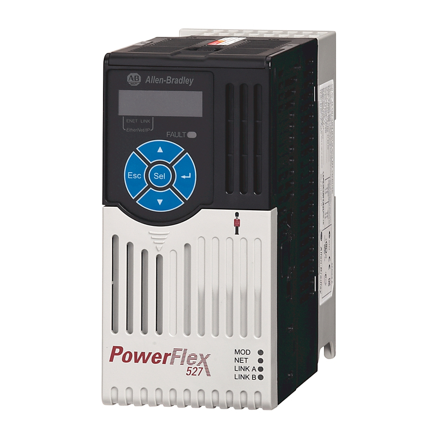
- Page 44 RM002 for more information. Understanding the The PowerFlex 527 drive has four status indicators, a fault indicator, an LCD display, and a membrane keypad for navigation. The display is used to view PowerFlex 527 Display and information such as motor information, axis states, faults, and set the network Indicators configuration.
- Page 45 Start Up Chapter 2 PowerFlex 527 Drive LCD Display and Status Indicators ENET and LINK display Fault status indicator Navigation keypad Module status indicator Network status indicator Link A status indicator (Ethernet Port 1) Link B status indicator (Ethernet Port 2)
- Page 46 Chapter 2 Start Up Startup Sequence On power-up, the drive will initialize VOLTS AMPS and status information will scroll across HERTZ the LCD display. PROGRAM After initialization, the Device/Axis state will be shown on the LCD display. In this example, the current state is STANDBY.
- Page 47 Provides information on the hardware and software HW Ver 01.002 FW Ver 01.102 versions. Device Info Provides information on the drive type, network PowerFlex 527 Static IP 192.168.1.180 configuration, and IP address. PowerFlex 527 DHCP 192.168.1.180 Settings Allows configuration of network settings, changing the Network Configuration on page 47 display language, and resetting the drive.
- Page 48 Chapter 2 Start Up Settings Options Settings Menu Sub Menu Attributes Default Description Selections Selections Network Static IP IP address 192.168.1.180 Indicates current IP address. Subnet mask 255.255.255.0 Indicates current subnet mask. Gateway 192.168.1.1 Indicates current gateway. DHCP IP address Automatically Indicates current IP address.
- Page 49 Start Up Chapter 2 Configuring Network Settings Step Keys Example Display 10.Press ESC to cancel a change and exit the edit mode. Press Enter to save a change and exit the edit mode. 11.Repeat step 7 step 10 to edit the values of the other octets.
- Page 50 I/O messaging services for control applications. Liner, Star, and Device Level Ring network topologies are supported by the PowerFlex 527 drive. Plus, the application of the CIP Safety protocol enables the simultaneous transmission of safety and standard control data and diagnostics information.
- Page 51 Add a PowerFlex 527 Drive Configure the PowerFlex 527 Drive Apply Power to the PowerFlex 527 Drive Test and Tune the Axes – Velocity and Position Control Modes Before you begin, make sure you know the catalog number for each drive component, the Logix module and /or controller used in your motion control application.
- Page 52 IP settings. Configure the Logix Designer These procedures assume that you have wired your PowerFlex 527 drive system. In this example, the CompactLogix™ 5370 controller is used. Application Project For help using the Studio 5000 Logix Designer (version 24 or greater) application as it applies to configuring the ControlLogix®...
- Page 53 Configuring the PowerFlex 527 Drive with Integrated Motion Chapter 3 The New Project dialog box appears. If you are configuring a PowerFlex 527 drive for integrated safety in a safety IMPORTANT application, you must use a GuardLogix® safety controller. If using a safety or non-safety ControlLogix controller, you must also use a 1756- EN2T, 1756-EN2TR, or 1756-EN3TR EtherNet/IP module.
- Page 54 Chapter 3 Configuring the PowerFlex 527 Drive with Integrated Motion The New Project dialog box appears. 4. From the Revision pull-down menu, choose your software revision. 5. Click Finish. The new controller appears in the Controller Organizer under the I/O Configuration folder.
- Page 55 Configuring the PowerFlex 527 Drive with Integrated Motion Chapter 3 The Select Module Type dialog box appears. 7. By using the filters, check Communication and Allen-Bradley, and select 1756-EN2T, 1756-EN2TR, or 1756-EN3TR as appropriate for your actual hardware configuration. In this example, the 1756-EN2T module is selected.
- Page 56 Chapter 3 Configuring the PowerFlex 527 Drive with Integrated Motion e. Enter the address of your EtherNet/IP module. In this example, the last octet of the address is 1. f. Click Change in the Module Definition area. The Module Definition dialog box opens.
- Page 57 16. Click OK. Add a PowerFlex 527 Drive Follow these instructions to add the PowerFlex 527 drive to your project. 1. Right-click the Ethernet network (node) and choose New Module..2. Clear the small ‘select all’ check boxes, Module Type Category and Vendor Filters.
- Page 58 Configuring the PowerFlex 527 Drive with Integrated Motion 3. In the Module Type Vendors Filters window, check Allen-Bradley. In the Module Type Category Filters window, check Drive. 4. Choose the PowerFlex 527 drive and click create. The Module Properties dialog box appears. 5. Configure the new drive.
- Page 59 Configure the PowerFlex 527 After you have added a PowerFlex 527 drive to your project, you will need to configure the type of safety connection suitable for your application. See the Drive following sections for instructions on configuring the drive for the different types of safety connections.
- Page 60 Chapter 3 Configuring the PowerFlex 527 Drive with Integrated Motion a. From the Electronic Keying pull-down menu, choose an option. WARNING: When using motion modules, the electronic keying must be either “Exact Match” or “Compatible Keying”. Never use “Disable Keying” with motion modules.
- Page 61 Configuring the PowerFlex 527 Drive with Integrated Motion Chapter 3 Configure Drive with Integrated Safety Connections Follow these steps to configure PowerFlex 527 drives with integrated safety. 1. Ensure that you have done the steps in Add a PowerFlex 527 Drive on page 57 before proceeding.
- Page 62 3. Click OK to close the Module Definition dialog box. 4. Click the Safety tab. The connection between the controller and the PowerFlex 527 drive is based on the following: • Drive catalog number must be PowerFlex 527 (integrated) •...
- Page 63 • Path from the GuardLogix controller to the PowerFlex 527 drive. • Configuration signature If any differences are detected, the connection between the GuardLogix controller and the PowerFlex 527 drive is lost, and the yellow icon appears in the controller project tree after you download the program. 5. Click Advanced.
- Page 64 Chapter 3 Configuring the PowerFlex 527 Drive with Integrated Motion Continue Drive Configuration After you have established your PowerFlex 527 drive in the Logix Designer application, the remaining configuration steps are the same regardless of the drive catalog number. 1. Right-click the PowerFlex 527 drive you just created and choose Properties.
- Page 65 Configuring the PowerFlex 527 Drive with Integrated Motion Chapter 3 The New Tag dialog box appears. 4. Type the axis Name. AXIS_CIP_DRIVE is the default Data Type. 5. Click Create. The axis (Axis_1 in this example) appears in the Controller Organizer under Motion Groups >...
- Page 66 Chapter 3 Configuring the PowerFlex 527 Drive with Integrated Motion 7. Click the Power tab. 8. From the pull-down menu, choose the power options appropriate for your actual hardware configuration. Attribute Menu Description PWM Frequency • 2 kHz The value sets the carrier frequency for the Pulse Width Modulation (PWM) output to the motor.
- Page 67 Configuring the PowerFlex 527 Drive with Integrated Motion Chapter 3 Configure the Motion Group Follow these steps to configure the motion group. 1. In the Controller Organizer, right-click Motion Groups and choose New Motion Group. The New Tag dialog box appears.
- Page 68 Configure Induction Motors Axis Properties (Position Loop) on page 77 • Configure Induction Motor Axis Properties (Frequency Control) The PowerFlex 527 drives support basic Volts/Hertz (V/Hz), Fan/Pump Volts/ Hertz, Sensorless Vector Control (SVC), and Sensorless Vector Control (SVC) Economy frequency control methods.
- Page 69 The General and Associated Module dialog box appears. 3. From the Axis Configuration pull-down menu, choose Frequency Control. 4. From the Module pull-down menu, your PowerFlex 527 drive. The Module Type and Power Structure fields populate with the chosen drive catalog number.
- Page 70 Chapter 3 Configuring the PowerFlex 527 Drive with Integrated Motion 8. From the Motor Type pull-down menu, choose Rotary Induction. 9. From the motor nameplate or datasheet, enter the phase-to-phase values. 10. Click Apply. 11. Select the Frequency Control category.
- Page 71 Configuring the PowerFlex 527 Drive with Integrated Motion Chapter 3 The Analyze Motor to Determine Motor Model dialog box appears. 16. Click the Static Motor Test tab. 17. Click Start to run the test and measure Motor Stator Resistance. If you chose the Basic Volts/Hertz category, you can skip this test.
- Page 72 Chapter 3 Configuring the PowerFlex 527 Drive with Integrated Motion Some out-of-box (OOB) settings will need to be applied here. See Recommended Out-of-Box Settings on page 163 for more information. 19. Select the Parameter List category. The Motion Axis Parameters dialog box appears.
- Page 73 The General and Associated Module dialog box appears. 3. From the Axis Configuration pull-down menu, choose Velocity Loop. 4. From the Module pull-down menu, your PowerFlex 527 drive. The Module Type and Power Structure fields populate with the chosen drive catalog number.
- Page 74 Chapter 3 Configuring the PowerFlex 527 Drive with Integrated Motion The Motor Device Specification dialog box appears. 7. From the Data Source pull-down menu, choose Nameplate Datasheet. This is the default setting. 8. From the Motor Type pull-down menu, choose Rotary Induction.
- Page 75 Configuring the PowerFlex 527 Drive with Integrated Motion Chapter 3 13. Click Apply. 14. Select the Scaling category and edit the values as appropriate for your application. 15. Click Apply if you make changes. 16. Select the Actions category. The Actions to Take Upon Conditions dialog box appears.
- Page 76 Chapter 3 Configuring the PowerFlex 527 Drive with Integrated Motion From this dialog box, you can program actions and change the action for exceptions (faults). See Logix5000 Controller and Drive Behavior on page 129 for more information. Some out-of-box (OOB) settings will need to be applied here. See Recommended Out-of-Box Settings on page 163 for more information.
- Page 77 The General and Associated Module dialog box appears. 3. From the Axis Configuration pull-down menu, choose Position Loop. 4. From the Module pull-down menu, your PowerFlex 527 drive. The Module Type and Power Structure fields populate with the chosen drive catalog number.
- Page 78 Chapter 3 Configuring the PowerFlex 527 Drive with Integrated Motion The Motor Device Specification dialog box appears. 7. From the Data Source pull-down menu, choose Nameplate Datasheet. This is the default setting. 8. From the Motor Type pull-down menu, choose Rotary Induction.
- Page 79 Configuring the PowerFlex 527 Drive with Integrated Motion Chapter 3 11. Select the Motor Feedback category. 12. Enter the specifications of your encoder into the fields. 13. Click Apply. 14. Select the Scaling category and edit the values as appropriate for your application.
- Page 80 Chapter 3 Configuring the PowerFlex 527 Drive with Integrated Motion 16. Select the Actions category. The Actions to Take Upon Conditions dialog box appears. From this dialog box, you can program actions and change the action for exceptions (faults). See...
- Page 81 Configuring the PowerFlex 527 Drive with Integrated Motion Chapter 3 The Motion Axis Parameters dialog box appears. From this dialog box, you can program actions and change the action for exceptions (faults). See Logix5000 Controller and Drive Behavior on page 129 for more information.
- Page 82 5 as shown below. SHOCK HAZARD: To avoid hazard of electrical shock, perform all mounting and wiring of the PowerFlex 527 drives prior to applying power. Once power is applied, connector terminals can have voltage present even when not in use.
- Page 83 Configuring the PowerFlex 527 Drive with Integrated Motion Chapter 3 Test and Tune the Axes – This procedure assumes that you have configured your PowerFlex 527 drive, your Logix5000 controller, and applied power to the system. Velocity and Position Control...
- Page 84 Chapter 3 Configuring the PowerFlex 527 Drive with Integrated Motion 4. In the Test Distance field, type 2.0 as the number of revolutions for the test. Test Description Marker Verifies marker detection capability as you rotate the motor shaft. Motor Feedback Verifies feedback connections are wired correctly as you rotate the motor shaft.
- Page 85 Configuring the PowerFlex 527 Drive with Integrated Motion Chapter 3 12. Click Accept Test Results. 13. If the test fails, this dialog box appears. a. Click OK. b. Verify the DC Bus voltage. c. Verify unit values entered in the Scaling category.
- Page 86 Chapter 3 Configuring the PowerFlex 527 Drive with Integrated Motion In this example, Travel Limit = 5 and Speed = 10. The actual value of programmed units depending on your application. 4. From the Direction pull-down menu, choose a setting appropriate for your application.
- Page 87 Explicit Messages Certification The TÜV Rheinland group has approved PowerFlex 527 drives with integrated safe torque-off for use in safety-related applications up to PLe, Category 3 according to EN ISO 13849, and SIL CL3 according to IEC 61508, EN 61800-...
- Page 88 The PowerFlex 527 drive STO function response time is less than 12 ms. Response time is the delay between the time the drive STO function receives the STO request and the time when motion producing power is removed from the motor.
- Page 89 PowerFlex 527 Integrated Safe Torque-Off Chapter 4 Probability of Dangerous Safety-related systems are classified as operating in a High-demand/continuous mode where the frequency of demands for operation made on a safety-related Failure Per Hour (PFH) system is greater than once per year.
- Page 90 For applications that do not require the safe torque-off feature, you must install jumper wires to bypass the safe torque-off circuitry. PowerFlex 527 drives ship with the safety control in the out-of-box state and with a safety bypass jumper in place. In this configuration, the PowerFlex 527 safe torque-off function is disabled.
- Page 91 Restoring the Drive to the Out-of-Box State After the integrated safety connection configuration is applied to the PowerFlex 527 drive at least once, you can follow these steps to restore your PowerFlex 527 drive to the out-of-box state. 1. Right-click the PowerFlex 527 drive you created, and choose Properties.
- Page 92 Chapter 4 PowerFlex 527 Integrated Safe Torque-Off 2. Click the Connection tab. The Connection tab appears. 3. Check Inhibit Module. 4. Click Apply, then click the Safety tab. The Safety tab appears. 5. In the Configuration Ownership field, click Reset Ownership.
- Page 93 SAFETY data) and may not be used as part of a safety function. Axis Tags When a PowerFlex 527 Add-On-Profile (AOP) is added to a Logix I/O tree, Axis tags are added to the controller tags. Safety-Related Axis Tags on page 93 lists the safety-related STANDARD tags that are added when a new AXIS_CIP_DRIVE axis is defined.
- Page 94 Chapter 4 PowerFlex 527 Integrated Safe Torque-Off Safety-Related Axis Tags (continued) Logix Designer Tag Name Attribute Type Description [bit] AxisSafetyStatus DINT SafetyFaultStatus BOOL Status of SI.SafetyFault SafetyResetRequestStatus BOOL Status of SO.ResetRequest SafetyResetRequiredStatus BOOL Status of SI.ResetRequired SafeTorqueOffActiveStatus BOOL Status of SO.SafeTorqueOff...
- Page 95 Safe Torque-Off Mode: Values Value Definition Accept a safety connection Block a safety connection Safe Torque-Off Mode The attribute STO Mode can be used to check if the PowerFlex 527 is in STO Bypass Mode. Safe Torque-Off Mode: MSG Parameter Value Description...
- Page 96 Chapter 4 PowerFlex 527 Integrated Safe Torque-Off The cause of the fault can be read using an explicit message: Safe Torque-Off Fault Type: MSG Parameter Value Description Service Code 0x0E Get Attribute Single Class 0x5A Safety Stop Functions Instance Axis number...
- Page 97 Chapter Hardwired Control of Safe Torque-Off This chapter introduces you to how the PowerFlex® 527 integrated safe torque-off feature is configured for hardwired control of safe torque-off. For information on... See page... Description of Operation Safe Torque-Off Connector Data Wire the Safe Torque-Off Circuit Safe Torque-Off Specifications Description of Operation The safe torque-off feature provides a method, with sufficiently low probability...
- Page 98 The GuardStopRequestStatus bit is set back to 0 if both inputs are in the ON state for 100 ms continuously (100 ms debounce time). Troubleshoot the Safe Torque-Off Function PowerFlex 527 Drive Troubleshooting Exception Code on Drive Display Fault Message...
- Page 99 Hardwired Control of Safe Torque-Off Chapter 5 System Operation in the Event that the Safety Enable Inputs Mismatch on page 99 demonstrates when the safe torque-off mismatch is detected and a GuardStopInputFault is posted. System Operation in the Event that the Safety Enable Inputs Mismatch (Safety Input) S1 (Safety Input) S2 1 second discrepancy limit...
- Page 100 Chapter 5 Hardwired Control of Safe Torque-Off Safe Torque-Off Connector PowerFlex 527 terminals S1, S2, and 01 are used for hardwired control of safe torque-off. Data Terminals for Safe Torque-Off (STO) Connection S1 S2 S+ Hardwired Safety Inputs Safety Bypass Jumper...
- Page 101 (1) Maximum and minimum sizes that the terminal block will accept. These are not recommended wire sizes. Safe Torque-Off To maintain their safety rating, PowerFlex 527 drives must be installed inside protected control panels or cabinets appropriate for the environmental Specifications conditions of the industrial location.
- Page 102 Chapter 5 Hardwired Control of Safe Torque-Off Notes: Rockwell Automation Publication 520-UM002B-EN-E - December 2017...
- Page 103 A 1756-L7xS GuardLogix or Compact GuardLogix 5370 safety controller is required for network control of the PowerFlex 527 safe torque-off function. The PowerFlex 527 safety connection can originate from a safety controller that provides both safety and motion control. The PowerFlex 527 safety connection can originate from a safety controller that controls only the safety, while a separate Logix processor controls motion.
- Page 104 The SO.Command tags are sent from the GuardLogix's safety output assembly to the PowerFlex 527 to control the safe torque-off function. The SI.Status tags are sent from the PowerFlex 527 to the GuardLogix safety input assembly and indicate the status of the PowerFlex 527's safety control.
- Page 105 SAFETY data with SIL 3 integrity. STO Fault Reset If a PowerFlex 527 drive safety control detects a fault, the input assembly tag SI.SafetyFault is set to 1. A transition from logic 0 to 1 of the SO.Reset tag is required after the SO.SafeTorqueOff tag has transitioned from logic 0 to 1.
- Page 106 Axis.SafetyFault tag to enable motion. Reset Safe Torque-Off Fault Diagram on page 106 for an understanding of the PowerFlex 527 STO Fault reset functionality. Reset Safe Torque-Off Fault Diagram Disable Torque Permit Torque Drv:SO.SafeTorqueOff...
- Page 107 Out-of-Box (OOB) Safety State on page Replacing a PowerFlex 527 drive that sits on an integrated safety network is more complicated than replacing standard devices because of the Safety Network Number (SNN). The device number and SNN make up the safety device's DeviceID.
- Page 108 Replacement with “Configure Only When No Safety Signature Exists” Enabled When a PowerFlex 527 drive is replaced and the DeviceID of the new drive matches the original, you can download the configuration from the safety controller. The DeviceID is a combination of the node/IP address and the safety network number (SNN), and is updated whenever the SNN is set.
- Page 109 Network Control of Safe Torque-Off Chapter 6 Scenario 1 – Replacement Integrated Safety Drive Is Out-of-Box and Safety Signature Exists 1. Remove and replace the existing integrated safety drive. 2. Right-click the replacement drive and choose Properties. The General tab appears in the Module Properties dialog box. 3.
- Page 110 Chapter 6 Network Control of Safe Torque-Off 5. Verify that the Network Status (NET) status indicator is alternating red/ green on the correct drive. 6. Click Yes to set the SNN and accept the replacement drive. 7. Power cycle the drive. 8.
- Page 111 Network Control of Safe Torque-Off Chapter 6 6. Right-click the replacement drive and chooses Properties. The General tab appears in the Module Properties dialog box. 7. Click to the right of the Safety Network Number (SNN). The Safety Network Number dialog box appears. 8.
- Page 112 Chapter 6 Network Control of Safe Torque-Off 9. Verify that the Network Status (NET) status indicator is alternating red/ green on the correct drive. 10. Power cycle the drive. 11. Follow your company-prescribed procedures to functionally test the replacement drive and system and to authorize the system for use. Scenario 3 –...
- Page 113 ATTENTION: Enable the Configure Always feature only if the entire integrated safety control system is not being relied on to maintain SIL 3 behavior during the replacement and functional testing of a PowerFlex 527 drive. Do not place drives that are in the Out-of-box condition on an integrated safety network when the Configure Always feature is enabled, except while following this replacement procedure.
- Page 114 Chapter 6 Network Control of Safe Torque-Off 3. Click the Safety tab. 4. Click Reset Ownership. 5. Click OK. 6. Follow your company-prescribed procedures to functionally test the replacement drive and system and to authorize the system for use. Motion Direct Commands in You can use the Motion Direct Command (MDC) feature to initiate motion while the controller is in Program mode, independent of application code that is Motion Control Systems...
- Page 115 Understanding STO Bypass When Using Motion Direct Commands If a Safety-only connection between the GuardLogix safety controller and the PowerFlex 527 drive was established at least once after the drive was received from the factory, the drive does not allow motion while the safety controller is in Program mode by default.
- Page 116 Chapter 6 Network Control of Safe Torque-Off Safety State Indications When Controller is in Run Mode (safety task executing) When the controller transitions to Program mode, the integrated safety drive is in the safe state and torque is not permitted. The controller will report Safety state = Not Running and Axis state = Start Inhibited, as shown in Safety State Indications After Controller Transitions to Program Mode on page...
- Page 117 Network Control of Safe Torque-Off Chapter 6 STO Bypass Prompt When the Safety Controller is in Program Mode The warning in STO Bypass Prompt When the Safety Controller is in Program Mode on page 117 is displayed the first time a motion direct command is issued. After you acknowledge the warning message by clicking Yes, torque is permitted by the drive and a warning message is indicated in the software as shown in Safety...
- Page 118 Chapter 6 Network Control of Safe Torque-Off The persistent warning message text Safe Torque Off bypassed appears when a IMPORTANT motion direct command is executed. The warning message persists - even after the dialog is closed and reopened - as long as the integrated safety drive is in STO Bypass mode. The persistent warning message is removed only after the integrated safety drive is restored to the Safe state.
- Page 119 Network Control of Safe Torque-Off Chapter 6 Axis and Safe State Indications on Motion Direct Commands Dialog Box Axis and Safe State Indications on the Motion Console Dialog Box Rockwell Automation Publication 520-UM002B-EN-E - December 2017...
- Page 120 Chapter 6 Network Control of Safe Torque-Off Functional Safety Considerations ATTENTION: Before maintenance work can be performed in Program mode, the developer of the application must consider the implications of allowing motion through motion direct commands and should consider developing logic for run-time maintenance operations to meet the requirements of machine safety operating procedures.
- Page 121 Display Interface The LCD display provides fault messages and troubleshooting information by using the soft menu items and navigation buttons. See Understanding the PowerFlex 527 Display and Indicators on page 44 for more information. Rockwell Automation Publication 520-UM002B-EN-E - December 2017...
- Page 122 Chapter 7 Troubleshooting When the drive enters a fault or INIT FLT M12 INVALID FPGA REV inhibit scenario, the fault information will be shown and scrolled across the LCD display. Fault type Fault description Fault code Fault Codes The fault code tables are designed to help you determine the source of the fault or exception.
- Page 123 Troubleshooting Chapter 7 FLT Sxx Fault Codes Exception Code on Display Exception Text Problem Possible Solutions FLT S10 – INV OVERCURRENT Inverter Overcurrent Fault Inverter current has exceeded the • Check motor power cable for shorts. instantaneous current limit (determined by •...
- Page 124 Chapter 7 Troubleshooting FLT Sxx Fault Codes Exception Code on Display Exception Text Problem Possible Solutions FLT S54 – POSN ERROR Excessive Position Error Fault The position error of the position control • Check position loop tuning. loop has exceeded the value given by •...
- Page 125 Troubleshooting Chapter 7 INIT FLT Fault Codes Exception Code on Display Exception Text Problem Possible Solutions INIT FLT S03 – NVMEM CHKSUM Nonvolatile memory checksum error Data in the nonvolatile memory has a • Cycle power. checksum error. • Reset the drive. •...
- Page 126 • Check controller and Ethernet switch during synchronous operation. operation. PowerFlex 527 Drive Status Indicators The fault status indicator is located between the LCD display and keypad. There are also four status indicators located at the bottom right of the drive and can be seen through the front cover of the control module.
- Page 127 Troubleshooting Chapter 7 Fault Status Indicator Condition Safety Supervisor State CIP Motion Axis State Governing Object Identity State Steady Red Any State Aborting Motion Axis Major Recoverable or Major Unrecoverable Steady Red Any State Major Faulted Motion Axis Major Recoverable or Major Unrecoverable Steady Red Abort...
- Page 128 Chapter 7 Troubleshooting Link A Status Indicator (Ethernet Port 1) Condition Status Drive is not connected to the network. Steady Green Drive is connected to the network but not transmitting data. Flashing Green Drive is connected to the network and transmitting data. Link A Status Indicator (Ethernet Port 2) Condition Status...
- Page 129 By using the Logix Designer application, you can configure how the Logix5000 Controller and PowerFlex 527 drives respond when a drive fault/exception occurs. Drive Behavior The INIT FLT xxx faults are always generated after powerup, but before the drive is enabled, so the stopping behavior does not apply.
- Page 130 Chapter 7 Troubleshooting PowerFlex 527 Drive Exception Behavior For PowerFlex 527 drives, you can configure exception behavior in the Logix Designer application from the Axis Properties dialog box, Actions category. PowerFlex 527 Drive Exception Action Definitions Exception Action Definition Ignore The controller completely ignores the exception condition.
- Page 131 Troubleshooting Chapter 7 Logix Designer Axis Properties - Actions Category Drive Behavior, FLT Sxx Fault Codes Exception Fault Code Exception Text Induction Fault Action Best Available Stopping Motor Action (applies to major Ignore Alarm Minor Major faults) Fault Fault FLT S03 – MTR OVERSPEED FL Motor Overspeed Factory Limit Fault Disable and Coast FLT S04 –...
- Page 132 Chapter 7 Troubleshooting Drive Behavior, FLT Mxx Fault Codes Exception Fault Code Exception Text Induction Fault Action Best Available Stopping Motor Action (applies to major Ignore Alarm Minor Major faults) Fault Fault FLT M10 – CONTROL MODULE Control Module Overtemperature Fault Disable and Coast OVERTEMPERATURE FL FLT M19 –...
- Page 133 See page... Certifications Environmental Specifications Technical Specifications Power Specifications Certifications Certifications PowerFlex 527 c-UL-us Listed to UL508C and CAN/CSA-C22.2 No. 14-05. Australian Communications and Media Authority In conformity with the following: Radiocommunications Act: 1992 Radiocommunications Standard: 2008 Radiocommunications Labelling Notice: 2008...
- Page 134 Appendix A Supplemental Drive Information Certifications PowerFlex 527 ODVA ODVA conformance tested to EtherNet/IP specifications Lloyd’s Register Lloyd’s Register Type Approval Certificate 15/80016(E1) IEEE P1668 Product meets the requirements of IEEE P1668 RoHS Compliant with the European “Restriction of Hazardous Substances” Directive...
- Page 135 Supplemental Drive Information Appendix A Technical Specifications Protection Specifications PowerFlex 527 Bus Overvoltage Trip 100...120V AC Input: 405V DC bus (equivalent to 150V AC incoming line) 200...240V AC Input: 405V DC bus (equivalent to 290V AC incoming line) 380...480V AC Input: 810V DC bus (equivalent to 575V AC incoming line) 525...600V AC Input:...
- Page 136 Appendix A Supplemental Drive Information Specifications PowerFlex 527 Performance with Encoder Closed Loop Velocity Vector Control: ±0.1% of base speed across a 100:1 speed range Output Voltage Range: 0V to rated motor voltage Output Frequency Range: 0...590 Hz (programmable) Efficiency: 97.5% (typical)
- Page 137 Supplemental Drive Information Appendix A Control Inputs Specifications PowerFlex 527 Digital Quantity: (4) Programmable Current: 6 mA Type Source Mode (SRC): 18...24V = ON, 0...6V = OFF Sink Mode (SNK): 0...6V = ON, 18...24V = OFF Analog Quantity: (2) Isolated, ±10V and 4-20mA...
- Page 138 Appendix A Supplemental Drive Information Power Specifications Watts Loss PowerFlex 527 Estimated Watts Loss (Rated Load, Speed & PWM) Voltage Output Current (A) Total Watts Loss 100...120V, 27.0 50/60 Hz 1-Phase 53.0 67.0 200...240V, 29.0 50/60 Hz 1-Phase 50.0 81.0 11.0...
- Page 139 Supplemental Drive Information Appendix A PowerFlex 527 Estimated Watts Loss (Rated Load, Speed & PWM) Voltage Output Current (A) Total Watts Loss 525...600V, 22.0 50/60 Hz 3-Phase 32.0 50.0 65.0 95.0 138.0 12.0 164.0 19.0 290.0 22.0 336.0 27.0 466.0 32.0...
- Page 140 Appendix A Supplemental Drive Information PowerFlex 527 Input Current Scaled By Motor Current Catalog Number Output Input 25C-D024N104 24.0 19.2 15.6 12.0 26.4 21.1 17.2 13.2 25C-D030N104 30.0 24.0 19.5 15.0 33.0 26.4 21.5 16.5 380...480V AC (-15%, +10%) – 3-Phase Input with EMC Filter, 0...460V 3-Phase Output...
- Page 141 Appendix Accessories and Dimensions Product Selection Catalog Number Description Drive Voltage Rating Rating Enclosure Emission Class Version PowerFlex 527 Drive Ratings Output Ratings Normal Duty Heavy Duty Output Input Frame Current (A) Voltage Range Size Catalog No. 100...120V AC (-15%, +10%) – 1-Phase Input, 0...230V 3-Phase Output 85...132...
- Page 142 Appendix B Accessories and Dimensions PowerFlex 527 Drive Ratings Output Ratings Normal Duty Heavy Duty Output Input Frame Current (A) Voltage Range Size Catalog No. 380...480V AC (-15%, +10%) – 3-Phase Input with EMC Filter, 0...460V 3-Phase Output 323...528 25C-D1P4N114 0.75...
- Page 143 Accessories and Dimensions Appendix B Dynamic Brake Resistors Drive Ratings Minimum Resistance Resistance Input Voltage ±10% ±5% (1)(2) Catalog No. 200...240V 0.25 AK-R2-091P500 50/60 Hz AK-R2-091P500 3-Phase 0.75 AK-R2-091P500 AK-R2-091P500 AK-R2-047P500 AK-R2-047P500 AK-R2-030P1K2 10.0 AK-R2-030P1K2 15.0 11.0 AK-R2-030P1K2 20.0 15.0 AK-R2-030P1K2...
- Page 144 Appendix B Accessories and Dimensions EMC Line Filters Drive Ratings Input Voltage Current (A) Frame Size Catalog No. 200...240V 0.25 25-RF011-AL 50/60 Hz 25-RF011-AL 1-Phase 0.75 25-RF011-AL 25-RF023-BL 11.0 25-RF023-BL 200...240V 0.25 25-RF014-AL 50/60 Hz 25-RF014-AL 3-Phase 0.75 25-RF014-AL 25-RF014-AL 11.0 25-RF014-AL 17.5...
- Page 145 160 drive. Replacement Parts PowerFlex 527 Power Module Item Description PowerFlex 527 Replacement power module for use with PowerFlex 527 drive. Includes: Power Module • Power Module • Power Module Front Cover • Power Terminal Guard • Heatsink Fan Output Ratings...
- Page 146 Appendix B Accessories and Dimensions Output Ratings Normal Duty Heavy Duty Output Input Frame Current (A) Voltage Range Size Catalog No. 200...240V AC (-15%, +10%) – 1-Phase Input with EMC Filter, 0...230V 3-Phase Output 170...264 25-PM2-A2P5 0.75 0.75 170...264 25-PM2-A4P8 170...264 25-PM2-A8P0 11.0...
- Page 147 20.0 15.0 27.0 446...660 25-PM1-E027 30.0 22.0 25.0 18.5 32.0 446...660 25-PM1-E032 PowerFlex 527 Control Module Frame Item Description Size Catalog No. PowerFlex 527 Replacement control module for use with A...E 25C-CTM1 Control Module PowerFlex 527 drives. Includes: • Control Module •...
- Page 148 Appendix B Accessories and Dimensions Bulletin 1321-3R Series Line Reactors (3)(4) (3)(4) Output Ratings Input Line Reactor Output Line Reactor IP00 IP11 IP00 IP11 Normal Duty Heavy Duty (Open Style) (NEMA/UL Type 1) (Open Style) (NEMA/UL Type 1) Catalog No. Catalog No.
- Page 149 Product Dimensions The PowerFlex® 527 drive is available in five frame sizes. See the PowerFlex 527 Drive Ratings on page 141 for information on power ratings. PowerFlex 527 Drive Weight Frame Size Weight (kg/lb) 1.1 / 2.4 1.6 / 3.5 2.3 / 5.0...
- Page 150 Appendix B Accessories and Dimensions IP 20/Open Type – Frame B Dimensions are in millimeters and (inches) 172.0 (6.77) 87.0 (3.43) 72.5 (2.85) 6.0 (0.24) IP 20/Open Type – Frame C Dimensions are in millimeters and (inches) 184.0 (7.24) 109.0 (4.29) 90.5 (3.56) 6.0 (0.24) Rockwell Automation Publication 520-UM002B-EN-E - December 2017...
- Page 151 Accessories and Dimensions Appendix B IP 20/Open Type – Frame D Dimensions are in millimeters and (inches) 212.0 (8.35) 130.0 (5.12) 116.0 (4.57) 6.0 (0.24) IP 20/Open Type – Frame E Dimensions are in millimeters and (inches) 185.0 (7.28) 279.0 (10.98) 160.0 (6.30) 7.6 (0.30) Rockwell Automation Publication 520-UM002B-EN-E - December 2017...
- Page 152 Appendix B Accessories and Dimensions Control Module Fan Kit 25-FAN1-70C 25-FAN2-70C Specifications 25-FAN1-70C 25-FAN2-70C Rated Voltage 24V DC Operation Voltage 14...27.6V DC Input Current 0.1 A 0.15 A Speed (Reference) 7000 rpm 4500 ± 10% rpm Maximum Air Flow (At zero static pressure) 0.575 m /min 1.574 m...
- Page 153 Accessories and Dimensions Appendix B IP 20/Open Type with Control Module Fan Kit – Frame D...E Dimensions are in millimeters and (inches) Frame D Frame E 196.0 (7.72) 185.0 (7.28) 130.0 (5.12) 160.0 (6.30) 116.0 (4.57) Remove the label to access the built-in 24V supply on drive frames D and E for use with the IMPORTANT Control Module Fan Kit.
- Page 154 Appendix B Accessories and Dimensions IP 30/NEMA 1/UL Type 1 – Frame A Dimensions are in millimeters and (inches) IP 30/NEMA 1/ UL Type 1 top panel 72.0 (2.83) 172.0 (6.77) 57.5 (2.26) 6.0 (0.24) IP 30/NEMA 1/ UL Type 1 conduit box 51.1 (2.01) 21.0 (0.82) ø21.5 (ø0.85)
- Page 155 Accessories and Dimensions Appendix B IP 30/NEMA 1/UL Type 1 – Frame B Dimensions are in millimeters and (inches) IP 30/NEMA 1/ UL Type 1 top panel 87.0 (3.43) 172.0 (6.77) 72.5 (2.85) 6.1 (0.24) IP 30/NEMA 1/ UL Type 1 conduit box 66.1 (2.60) 63.1 (2.48) 33.5 (1.32)
- Page 156 Appendix B Accessories and Dimensions IP 30/NEMA 1/UL Type 1 – Frame C Dimensions are in millimeters and (inches) IP 30/NEMA 1/ UL Type 1 top panel 109.0 (4.29) 90.5 (3.56) 184.0 (7.24) 6.0 (0.24) IP 30/NEMA 1/ UL Type 1 conduit box 80.5 (3.17) 66.5 (2.62) 34.5 (1.36)
- Page 157 Accessories and Dimensions Appendix B IP 30/NEMA 1/UL Type 1 – Frame D Dimensions are in millimeters and (inches) IP 30/NEMA 1/ UL Type 1 top panel 130.0 (5.12) 212.0 (8.35) 116.0 (4.57) 6.0 (0.24) IP 30/NEMA 1/ UL Type 1 conduit box 96.0 (3.78) 70.0 (2.76) 44.0 (1.73)
- Page 158 Appendix B Accessories and Dimensions IP 30/NEMA 1/UL Type 1 – Frame E Dimensions are in millimeters and (inches) IP 30/NEMA 1/ UL Type 1 top panel 185.0 (7.28) 160.0 (6.30) 279.0 (10.98) 7.6 (0.30) IP 30/NEMA 1/ UL Type 1 conduit box 127.5 (5.02) 82.5 (3.25) 62.5 (2.46)
- Page 159 Accessories and Dimensions Appendix B EMC Line Filter – Frame A Dimensions are in millimeters and (inches) Filter can be mounted onto the back of the drive. 55.0 (2.17) 72.0 (2.83) 30.0 (1.18) 54.0 (2.13) ø5.5 (ø0.22) 234.0 223.0 (9.21) 223.0 (8.78) (8.78) 20.0 (0.79)
- Page 160 Appendix B Accessories and Dimensions EMC Line Filter – Frame C Dimensions are in millimeters and (inches) Filter can be mounted onto the back of the drive. 70.0 (2.76) 109.0 (4.29) 37.0 (1.46) 76.0 (2.99) ø5.5 (ø0.22) 275.0 (10.83) 263.0 263.0 (10.35) (10.35)
- Page 161 Replacing the PowerFlex 527 Control Module Internal Fan To replace the internal fan, you need to separate the control module from the power module. Do not perform this operation while the drive is running. See the PowerFlex 527 Control Module Internal Fan Kit Installation Instructions, publication 520-IN014 for detailed instructions.
- Page 162 Appendix B Accessories and Dimensions Notes: Rockwell Automation Publication 520-UM002B-EN-E - December 2017...
- Page 163 Appendix Out-of-Box Configuration This section describes the recommended settings for configuring your PowerFlex® 527 drive to obtain the best performance from the drive. You should apply these out-of-box settings first before configuring for your application. Recommended Out-of-Box Settings Setting in Logix Designer Example Recommended Configuration 120% of Motor Rated Speed for induction...
- Page 164 Appendix C Out-of-Box Configuration Setting in Logix Designer Example Recommended Configuration Torque Limits 200% of Motor Rated Torque Velocity Error Tolerance Change action to alarm Feedback Tap Rockwell Automation Publication 520-UM002B-EN-E - December 2017...
- Page 165 Out-of-Box Configuration Appendix C Setting in Logix Designer Example Recommended Configuration Application Type setting in Constant Speed Velocity Loop Motion Group Base Update Rate 4 ms Rockwell Automation Publication 520-UM002B-EN-E - December 2017...
- Page 166 Out-of-Box Configuration Setting the ACO/AVO The attribute ACO/AVO (Analog Current Output/Analog Voltage Output) can be used to set the analog output of the PowerFlex 527 drive to either Attribute current (mA) or voltage (V). Ensure that the Analog Out jumper ( J2) is also set to the same value. See...
- Page 167 Appendix Encoder Option Card Usage Installing the Encoder Option To install the encoder option card: Card 1. Separate the power module and control module. See Separating the Power and Control Module on page 25 for instructions. 2. Place the encoder option card on the back of the control module. Ensure that the tabs on the encoder option card are aligned with the slots on the control module.
- Page 168 Appendix D Encoder Option Card Usage Removing the Encoder To remove the encoder option card: Option Card 1. Hold the top of the encoder option card firmly as shown below and pull out to remove. Do not remove the encoder option card from the bottom as it may damage the IMPORTANT card and the locking mechanism on the control module.
- Page 169 Encoder Option Card Usage Appendix D In the Motor Feedback configuration, enter the resolution of the encoder used. Encoder Interface The incremental encoder option card can source 5 or 12 volt power and accept 5, 12 or 24 volt single ended or differential inputs. See Appendix B for ordering information.
- Page 170 Appendix D Encoder Option Card Usage Encoder Wiring Examples Connection Example Connection Example Encoder Power Encoder Power +12V DC (250 mA) – Internal Drive – External Power Power Source Common SHLD to SHLD External Internal (drive) Power Supply 12V DC, 250mA Encoder Signal Encoder Signal to Power Supply...
- Page 171 Index accessing inputs control terminals circuit breakers power terminals power auxiliary contact drive motor ground basic operation start stop drive mount drive mounting dimensions circuit breakers inputs ratings control terminals noise immunity accessing wiring derating output temperature dimensions disconnect mounting disconnect output power...
- Page 172 shielded unshielded wiring wiring shielding ground start voltage reflections motor stop wiring motor storage environment wave protection reflected wiring temperature encoder noise immunity derating recommended wiring shielded tools temperature programming unshielded voltage reflections Rockwell Automation Publication 520-UM002B-EN-E - December 2017...
- Page 173 Notes: Rockwell Automation Publication 520-UM002B-EN-E - December 2017...
- Page 174 Notes: Rockwell Automation Publication 520-UM002B-EN-E - December 2017...
- Page 176 Rockwell Automation Support Rockwell Automation provides technical information on the Web to assist you in using its products. , you can find technical manuals, a knowledge base of FAQs, technical and http://www.rockwellautomation.com/support/ application notes, sample code and links to software service packs, and a MySupport feature that you can customize to make the best use of these tools.