Allen-Bradley Compact GuardLogix 5370 User Manual
Hide thumbs
Also See for Compact GuardLogix 5370:
- Reference manual (172 pages) ,
- Original instructions manual (19 pages)
Table of Contents
Quick Links
See also:
Reference Manual
Table of Contents

Related Manuals for Allen-Bradley Compact GuardLogix 5370


Summary of Contents for Allen-Bradley Compact GuardLogix 5370
- Page 1 User Manual Original Instructions Compact GuardLogix 5370 Controllers Catalog Numbers 1769-L30ERMS, 1769-L33ERMS, 1769-L33ERMSK, 1769-L33ERMOS, 1769-L36ERMS, 1769-L36ERMOS, 1769-L37ERMOS, 1769-L37ERMS, 1769-L38ERMOS, 1769-L38ERMS...
- Page 2 Important User Information Read this document and the documents listed in the additional resources section about installation, configuration, and operation of this equipment before you install, configure, operate, or maintain this product. Users are required to familiarize themselves with installation and wiring instructions in addition to requirements of all applicable codes, laws, and standards.
-
Page 3: Table Of Contents
European Hazardous Location Approval ....23 Compact GuardLogix 5370 Controller Parts ....23 Install the Secure Digital (SD) Card . - Page 4 Table of Contents Chapter 3 Complete the Controller Setup Set the IP Address ..........33 Use the BOOTP Server to Set the lP Address .
- Page 5 Table of Contents Chapter 6 Add and Configure Standard I/O ............. . 83 Select I/O Modules.
- Page 6 Table of Contents Chapter 7 Add, Configure, Monitor, and ............. 105 Add Safety I/O Devices.
- Page 7 Table of Contents Chapter 9 Develop Safety Applications The Safety Task ..........142 Safety Task Period Specification .
- Page 8 Table of Contents Chapter 12 Monitor Status and Handle Faults View Status via the Online Bar ....... . 177 Monitor Connections .
-
Page 9: Summary Of Changes
Summary of Changes This manual contains new and updated information as indicated in the following table. Topic Page 1769-L37ERMS, 1769-L38ERMOS, 1769-L38ERMS added Throughout System Overview Controller Functionality Programming Requirement Nodes on EtherNet/IP Network EtherNet/IP Network Connections Local Expansion Modules Module Power Consumption Calculation for a Local Bank Motion Axes Support Position Loop-configured Drive Limits Rockwell Automation Publication 1769-UM022C-EN-P - June 2018... - Page 10 Summary of Changes Notes: Rockwell Automation Publication 1769-UM022C-EN-P - June 2018...
-
Page 11: Preface
Compact GuardLogix® 5370 controller. This manual is intended for automation engineers and control system developers. Compact GuardLogix 5370 controllers are designed to provide solution for small and medium-sized applications. This table defines terms that are used in this manual. -
Page 12: Additional Resources
These resources contain information about related products from Rockwell Automation. Resource Description GuardLogix 5570 and Compact GuardLogix 5370 Controller Systems Safety Provides information on safety application requirements for GuardLogix 5570 and Compact Reference Manual, publication 1756-RM099 GuardLogix 5370 controllers in Studio 5000 Logix Designer® applications. - Page 13 Preface Resource Description PowerFlex® 527 Adjustable Frequency AC Drive User Manual, Provides information to install, start up, and troubleshoot the PowerFlex 520-series adjustable publication 520-UM002 frequency AC drive. Industrial Automation Wiring and Grounding Guidelines, publication 1770-4.1 Provides general guidelines to install a Rockwell Automation® industrial system. Product Certifications website, Provides declarations of conformity, certificates, and other certification details.
- Page 14 Preface Notes: Rockwell Automation Publication 1769-UM022C-EN-P - June 2018...
-
Page 15: System Overview
Page Safety Application Requirements Distinguishing Between Standard and Safety Components Controller Data Flow Capabilities Compact GuardLogix 5370 Controller System Programming Requirement The Compact GuardLogix® 5370 controllers offer state-of-the-art control, communication, and I/O elements in a distributed control package. This product family includes the following Compact GuardLogix controllers: •... -
Page 16: Safety Application Requirements
Chapter 1 System Overview Safety Application The Compact GuardLogix 5370 controller system is certified for use in safety applications up to and including Safety Integrity Level (SIL) 3 and Requirements Performance Level (PL)e, in which the de-energized state is the safe state. -
Page 17: Distinguishing Between Standard And Safety Components
System Overview Chapter 1 Distinguishing Between Slots in the Compact GuardLogix backplane not used by the safety function can be populated with other CompactLogix modules that are certified to the Standard and Safety Low Voltage and EMC Directives. Components See the product certifications at http://www.rockwellautomation.com/global/ certification/overview.page to find the CE certificate for the Programmable... -
Page 18: Controller Data Flow Capabilities
Safety tags can be read or written by safety logic. Safety tags can be exchanged between safety controllers over an Ethernet network, including GuardLogix 5570 and Compact GuardLogix 5370 controllers. Safety tag data, program- or controller-scoped, can be read by external devices, such as HMI devices, personal computers, or other standard controllers. -
Page 19: Compact Guardlogix 5370 Controller System
• RSLinx® Classic software, version 3.80.xx or later • RSNetWorx™ for DeviceNet software, version 25.00.00 or later Secure Digital (SD) card • 1784-SD1 card - Ships with the Compact GuardLogix 5370 controller and offers 1 GB of for external nonvolatile memory memory •... -
Page 20: Programming Requirement
Chapter 1 System Overview Table 3 to identify the programming tool and the versions for use with Programming Requirement your Compact GuardLogix 5370 controllers. Table 3 - Software Versions Studio 5000® RSLinx Classic Cat. No. Environment Software Version 1769-L30ERMS 28.00.00 or later 3.80 or later... -
Page 21: Install The Controller
Chapter Install the Controller Topic Page Precautions Compact GuardLogix 5370 Controller Parts Install the Secure Digital (SD) Card Plan the System Assemble the System Mount the System Mount the System Connect Power to the Control System Connect to the Controller via a USB Cable... -
Page 22: North American Hazardous Location Approval
Chapter 2 Install the Controller North American Hazardous Location Approval The following information applies when operating this equipment in Informations sur l’utilisation de cet équipement en environnements hazardous locations. dangereux. Products marked “CL I, DIV 2, GP A, B, C, D” are suitable for use in Class Les produits marqués “CL I, DIV 2, GP A, B, C, D”... -
Page 23: European Hazardous Location Approval
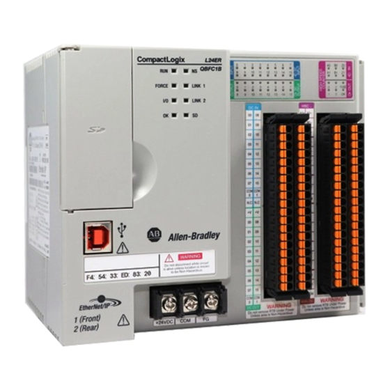
• Do not disconnect equipment unless power has been removed or the area is known to be nonhazardous. Compact GuardLogix 5370 These parts are included in the box when you order your controller: • Controller - Specific catalog number varies by order Controller Parts •... -
Page 24: Install The Secure Digital (Sd) Card
Chapter 2 Install the Controller Install the Secure Digital (SD) Compact GuardLogix® 5370 controllers ship from the factory with the 1784-SD1 SD card installed. Card Complete these steps to reinstall a removed SD card into the controller or to install a new SD card into the controller. We recommend that you leave the SD card in the controller, even when it is not used. -
Page 25: Plan The System
A 1769-ECx end cap is required to terminate the end of the last bank in the control system. For example, if a Compact GuardLogix 5370 controller system uses one bank, you must use a 1769-ECR right end cap to terminate the right end of the bank. -
Page 26: Assemble The System
Physical Placement of I/O Modules on page 91 for requirements related to Compact I/O local expansion modules. For examples of Compact GuardLogix 5370 controller systems that use one bank or multiple banks, see Mount the System on page ATTENTION: Compact GuardLogix 5370 controller systems do not support removal and insertion under power (RIUP). -
Page 27: Mount The System
Install the Controller Chapter 2 4. Use the upper and lower tongue-and-groove slots to secure the controller and power supply together. Upper Tongue-and-groove Slot Lower Tongue-and-groove Slot 5. Move the power supply back along the tongue-and-groove slots until the bus connectors align with each other. 6. - Page 28 Chapter 2 Install the Controller You can mount a Compact GuardLogix 5370 controller system on a panel or on a DIN rail. ATTENTION: During panel or DIN rail mounting of all devices, be sure that all debris (such as metal chips or wire strands) is kept from falling into the controller.
-
Page 29: Minimum Spacing
Install the Controller Chapter 2 Minimum Spacing Maintain spacing from enclosure walls, wireways, and adjacent equipment. Allow 50 mm (2 in.) of space on all sides, as shown. This spacing provides ventilation and electrical isolation. 50 mm (2 in.) 50 mm 50 mm (2 in.) (2 in.) -
Page 30: Mount The Controller On A Panel
6 for any remaining modules. … Mount the Controller on a DIN Rail You can mount the Compact GuardLogix 5370 controller on the following DIN rails: • EN 50 022 - 35 x 7.5 mm (1.38 x 0.30 in.) • EN 50 022 - 35 x 15 mm (1.38 x 0.59 in.) ATTENTION: This controller is grounded to chassis ground through the DIN rail. -
Page 31: Connect Power To The Control System
Compact I/O Expansion Power Supplies Installation Instructions, publication 1769-IN028. Connect to the Controller The Compact GuardLogix 5370 controller has a USB port that uses a Type B receptacle. The port is USB 2.0-compatible and operates at 12 Mbps. via a USB Cable Use a USB cable to connect your computer to the USB port. -
Page 32: Connect The Controller To An Ethernet/Ip Network
EtherNet/IP Network Connections on page Connect to Different EtherNet/IP Network Topologies The Compact GuardLogix 5370 controllers have embedded switch technology and two EtherNet/IP ports that let you use it in different EtherNet/IP network topologies: • Device-level Ring network topology - Both ports on the controller are connected to the network with requirements about how the connections are made. -
Page 33: Set The Ip Address
Chapter Complete the Controller Setup Topic Page Set the IP Address Change the IP Address Load Controller Firmware Select the Operating Mode of the Controller To complete the tasks that are described in this chapter, you must have the following software installed on your computer. •... -
Page 34: Use The Bootp Server To Set The Lp Address
You are not required to set an IP address each time that power is cycled to the controller. You can use these tools to set the IP address of a Compact GuardLogix 5370 controller: • Bootstrap Protocol (BOOTP) server •... -
Page 35: Use The Dhcp Server To Set The Lp Address
Complete the Controller Setup Chapter 3 There are two conditions in which the Compact GuardLogix 5370 controllers use the BOOTP servers to set the IP address of the controller: • Initial power-up - Because the Compact GuardLogix 5370 controller ships with BOOTP-enabled, when it is first powered up, the controller sends a request for an IP address on the EtherNet/IP network. -
Page 36: Use The Rslinx Classic Software To Set The Lp Address
Complete these steps to set the IP address of the controller with RSLinx software. IMPORTANT These steps show a 1769-L36ERMS controller. The same steps would also apply to all Compact GuardLogix 5370 controllers with slight variations in screens. 1. Make sure that a USB cable is connected to your computer and the controller. - Page 37 Complete the Controller Setup Chapter 3 The RSWho dialog box appears and includes the USB driver. 4. Right-click the EtherNet/IP module and choose Module Configuration. The Module Configuration dialog box appears. 5. Click the Port Configuration tab. 6. For Network Configuration Type, select Static to assign this configuration to the port.
-
Page 38: Use The Studio 5000 Environment To Set The Lp Address
Complete these steps to set the IP address of the controller. IMPORTANT These steps show a 1769-L36ERMS controller. The same steps also apply to all Compact GuardLogix 5370 controllers with slight variations in screens. 1. Start the Logix Designer application. - Page 39 Complete the Controller Setup Chapter 3 5. Click Download. 6. Click Download again. The new project is downloaded to the controller and the project goes online, in Remote Program or Program mode. 7. Right-click the controller name and choose Properties. Rockwell Automation Publication 1769-UM022C-EN-P - June 2018...
- Page 40 Chapter 3 Complete the Controller Setup 8. On the Controller Properties dialog box, click the Internet Protocol tab. The IP Settings Configuration values show that the controller has no IP address that is assigned to it. 9. Click Manually configure IP settings. 10.
-
Page 41: Use The Sd Card To Set The Lp Address
Use the SD Card to Set the lP Address You can use an SD card to set the IP address for a Compact GuardLogix 5370 controller. If you use the SD card to set the IP address, then it removes the need for software to complete this task. -
Page 42: Change The Ip Address
Complete the Controller Setup Change the IP Address You can change the IP address of a Compact GuardLogix 5370 controller after system operation has begun. In this case, the controller has an IP address that is assigned to it, but you must change that IP address. -
Page 43: Change The Ip Address With Rslinx Software
Complete these steps to change the IP address of the controller. IMPORTANT These steps show a 1769-L36ERMS controller. The same steps also apply to all Compact GuardLogix 5370 controllers with slight variations in screens. 1. Verify that a USB cable is connected to your computer and the controller. -
Page 44: Change The Ip Address With Logix Designer Software
Complete the Controller Setup Change the IP Address with Logix Designer Software You can change the IP address of a Compact GuardLogix 5370 controller via Logix Designer application over a USB or EtherNet/IP network connection. Complete these steps to change the IP address of the controller. -
Page 45: Change The Ip Address With An Sd Card
• A project is stored on the SD card. • The project that is stored on the SD card includes another IP address for the Compact GuardLogix 5370 controller than the IP address currently in use on the physical controller that houses the SD card. -
Page 46: Use The Controlflash Software To Load Firmware
Complete these steps to use the ControlFLASH software to load firmware. IMPORTANT These steps show a 1769-L36ERMS controller. The same steps would also apply to all Compact GuardLogix 5370 controllers with slight variations in screens. 1. Verify that a connection exists between your computer and the Compact GuardLogix 5370 controller. - Page 47 Complete the Controller Setup Chapter 3 3. When the Welcome dialog box appears, click Next. 4. Choose the controller catalog number and click Next. 5. Expand the network until you see the controller. Rockwell Automation Publication 1769-UM022C-EN-P - June 2018...
- Page 48 Chapter 3 Complete the Controller Setup 6. Choose the controller at the first instance in which it appears, as shown in the following graphic, and click OK. 7. Choose the revision level to which you want to update the controller and click Next.
-
Page 49: Use The Autoflash Utility To Load Firmware
Complete the Controller Setup Chapter 3 Before the firmware upgrade begins, you see the following dialog box. Take the required action for your application. In this example, the upgrade continues when OK is clicked. After the controller is updated, the status dialog box displays that the update is complete. - Page 50 Complete these steps to use the AutoFlash utility to load firmware. IMPORTANT These steps show a 1769-L36ERMS controller. The same steps would also apply to all Compact GuardLogix 5370 controllers with slight variations in screens. 1. Make sure that the network connection is made and your network driver is configured in RSLinx Classic software.
- Page 51 Complete the Controller Setup Chapter 3 A dialog box appears to indicate that the project revision and controller firmware revision are different. 6. Click Update Firmware. 7. Use the check box and pull-down menu to choose your controller and firmware revision. 8.
-
Page 52: Use The Secure Digital Card To Load Firmware
• You must have saved the project to the SD card before the power cycle. • The firmware revision in the project that is stored on the SD card differs from the firmware revision on the Compact GuardLogix 5370 controller. Additional requirements apply for safety projects. See... -
Page 53: Select The Operating Mode Of The Controller
This could cause an explosion in hazardous location installations. Be sure that power is removed or the area is nonhazardous before you proceed. The following graphic shows the mode switch on a Compact GuardLogix 5370 controller. Use the mode switch on the controller to set the operating mode. - Page 54 Chapter 3 Complete the Controller Setup IMPORTANT Restrictions apply for safety applications. See Chapter Develop Safety Applications, and the GuardLogix 5570 and Compact GuardLogix 5370 Safety Reference Manual, publication 1756-RM099, for detailed information on programming restrictions. Mode Switch Position Description You can perform these tasks: •...
-
Page 55: Configure The Controller
Chapter Configure the Controller Topic Page Create a Controller Project Set Passwords for Safety -lock and -unlock Set Passwords for Safety -lock and -unlock Protect the Safety Task Signature in Run Mode I/O Device Replacement Options Enable Time Synchronization Configure a Peer Safety Controller Create a Controller Project To configure and program your controller, follow these steps to create and manage a project for the controller with the Logix Designer application. - Page 56 Chapter 4 Configure the Controller 3. Choose a Compact GuardLogix 5370 controller: • 1769-L30ERMS • 1769-L33ERMS • 1769-L36ERMS • 1769-L37ERMS • 1769-L38ERMS 4. In the Name field, type the name of the project. 5. Click Browse to specify the folder for storing the safety controller project.
- Page 57 Configure the Controller Chapter 4 7. From the Revision pull-down menu, choose the major revision of firmware for the controller. 8. From the Security Authority pull-down menu, choose a security authority option. For detailed information on security, refer to the Logix 5000™ Controllers Security Programming Manual, publication 1756-PM016.
- Page 58 Chapter 4 Configure the Controller This SNN defines the EtherNet/IP on which the controller resides as a safety subnet. It can be viewed and modified via the General tab on the Controller Properties dialog box. For most applications, this automatic, time-based SNN is sufficient. However, there are cases when you need to enter a specific SNN.
-
Page 59: Set Passwords For Safety -Lock And -Unlock
Configure the Controller Chapter 4 Set Passwords for You can safety-lock the controller to help protect safety control components from modification. Only safety components, such as the safety task, safety Safety -lock and -unlock programs, safety routines, and safety tags are affected. Standard components are unaffected. -
Page 60: Protect The Safety Task Signature In Run Mode
Chapter 4 Configure the Controller Protect the Safety Task You can prevent the safety task signature from being either generated or deleted while the controller is in Run or Remote Run mode, regardless of whether the Signature in Run Mode safety application is locked or unlocked. -
Page 61: Electronic Keying
Configure the Controller Chapter 4 Electronic Keying Electronic keying reduces the possibility that you use the wrong device in a control system. It compares the device defined in your project to the installed device. If keying fails, a fault occurs. These attributes are compared. Attribute Description Vendor... -
Page 62: I/O Device Replacement Options
Chapter 4 Configure the Controller I/O Device Replacement The Safety tab of the Controller Properties dialog box lets you define how the controller handles the replacement of an I/O device in the system. This option Options determines whether the controller sets the safety network number (SNN) of an I/O device that it is connected to and has configuration data for when a safety task signature exists. -
Page 63: Enable Time Synchronization
Configure the Controller Chapter 4 Enable Time Synchronization In a Compact GuardLogix 5370 controller system, the controller must be designated as the coordinated system time (CST) master. Time synchronization provides a standard mechanism to synchronize clocks across a network of distributed devices. - Page 64 Chapter 4 Configure the Controller Notes: Rockwell Automation Publication 1769-UM022C-EN-P - June 2018...
-
Page 65: Communicate Over Networks
• Produce/consume (interlock) data between controllers • Socket interface Compact GuardLogix 5370 controllers support these tasks over a DeviceNet network: • Control distributed I/O only for standard connections • Send messages to devices on the same network; the controller cannot receive messages from other devices on the network. -
Page 66: Managing The Safety Network Number (Snn)
Chapter 5 Communicate Over Networks Managing the Safety Network Number (SNN) The SNN assigned to safety devices on a network segment must be unique. You must be sure that a unique SNN is assigned to each CIP Safety network that contains safety devices. The SNN assigned to safety devices on a network segment must be unique. -
Page 67: Assigning The Safety Network Number (Snn)
Communicate Over Networks Chapter 5 Manual SNN If the manual format is selected, the SNN represents entered values from 1…9999 decimal. Figure 8 - Manual-based SNN Format Assigning the Safety Network Number (SNN) You can allow the Logix Designer application to automatically assign an SNN, or you can assign the SNN manually. -
Page 68: Changing The Safety Network Number (Snn)
Chapter 5 Communicate Over Networks Automatic Versus Manual For typical users, the automatic assignment of an SNN is sufficient. However, manual manipulation of the SNN is required if the following is true: • Safety consumed tags are used. • The project consumes safety input data from a module whose configuration is owned by some other device. - Page 69 Communicate Over Networks Chapter 5 3. Click Time-based and then Generate. 4. Click OK. Change the SNN of Safety I/O Modules on the CIP Safety Networks 1. In the Controller Organizer, double-click the first safety I/O module underneath the Ethernet network to view the General tab. 2.
- Page 70 Chapter 5 Communicate Over Networks 3. Choose Time-based and click Generate to generate a new SNN for that EtherNet/IP network. 4. Click OK. 5. Click Copy to copy the new SNN to the Windows Clipboard. 6. Open the General Tab of the Module Properties dialog box of the next safety I/O module under that EtherNet/IP module.
- Page 71 Communicate Over Networks Chapter 5 Copy and Paste a SNN If the module’s configuration is owned by another controller, you may need to copy and paste the SNN from the configuration owner into the module in your I/O configuration tree. 1.
-
Page 72: Ethernet/Ip Network Communication
The Compact GuardLogix 5370 controllers use socket interface transactions and conventional communication over the EtherNet/IP network to communicate with Ethernet devices that do not support the EtherNet/IP application protocol. -
Page 73: Nodes On Ethernet/Ip Network
1769-L38ERMS 1769-L38ERMOS (1) Available at firmware revision 31. IMPORTANT While Compact GuardLogix 5370 controllers offer the option of using Ethernet node count to effectively design a control system, the controllers do have connection limits on an EtherNet/IP network. For more information on how to design EtherNet/IP network use in your Compact GuardLogix 5370 controller system, see these resources: •... -
Page 74: Ethernet/Ip Network Topologies
• HMIs that are not added to the I/O configuration section, for example, PanelView™ Plus terminals • MSG instructions • Devices with which the Compact GuardLogix 5370 controllers use a socket interface to communicate. For example, the following devices require communication via a socket interface: –... - Page 75 Communicate Over Networks Chapter 5 Compact GuardLogix 5370 controllers connect directly to a DLR network topology, that is, without requiring a 1783-ETAP tap to connect to the network. The controllers can function in any of the roles on a DLR network topology, that is, active supervisor node, back-up supervisor node or ring node.
- Page 76 Chapter 5 Communicate Over Networks Figure 10 - Example 1769-L33ERMS Control System With a Linear Network Topology 1734-AENTR POINT I/O • 1794-AENT FLEX PanelView Plus • 1783-ETAP Kinetix 5500 1769-L33ERMS • PowerFlex® 525 • 1783-ETAP Star Network Topology A star network topology is a traditional EtherNet/IP network that includes multiple devices that are connected to each other via an Ethernet switch.
-
Page 77: Ethernet/Ip Network Connections
Ethernet devices that do not support the EtherNet/IP application protocol. Examples of devices that do not support the EtherNet/IP application protocol but can be used in a Compact GuardLogix 5370 controller application include the following: • Modbus TCP/IP device... -
Page 78: Quality Of Service (Qos) And I/O Module Connections
Compact GuardLogix 5370 controllers support Quality of Service (QoS) technology. QoS lets the controller prioritize EtherNet/IP network traffic. By default, the Compact GuardLogix 5370 controllers are QoS-enabled. QoS can be disabled by configuring a message instruction in the Logix Designer application. -
Page 79: Devicenet Network Communication
Communicate Over Networks Chapter 5 DeviceNet Network The Compact GuardLogix 5370 controllers communicate with other devices over the DeviceNet network via a Compact I/O™ 1769-SDN DeviceNet Communication scanner. The DeviceNet network uses the Common Industrial Protocol (CIP) to provide the control, configuration, and data collection capabilities for industrial devices. -
Page 80: Compact I/O 1769-Sdn Devicenet Scanner
Chapter 5 Communicate Over Networks Compact I/O 1769-SDN DeviceNet Scanner You can connect a Compact GuardLogix 5370 controller to a DeviceNet network via a Compact I/O 1769-SDN DeviceNet scanner for standard communication. IMPORTANT CIP Safety is not supported on a DeviceNet network with the 1769-SDN scanner. -
Page 81: Rockwell Automation Publication 1769-Um022C-En-P - June
Compact GuardLogix 5370 controller systems also support the use of extra banks for the local expansion modules of the system. Each additional bank requires a 1769 Compact I/O power supply. - Page 82 Chapter 5 Communicate Over Networks Current Capacity in Compact GuardLogix 5370 Controller Systems In a local or extra bank, the modules that are installed on either side of the power supply cannot draw more current than the power supply can supply.
-
Page 83: Select I/O Modules
• Standard Distributed I/O Modules Over a DeviceNet Network Local Expansion Modules Compact GuardLogix 5370 controller systems support the use of standard Compact I/O™ modules as local expansion modules along a CompactBus backplane. Consider the following when using local expansion modules: •... -
Page 84: Add And Configure Standard I/O Modules
Chapter 6 Add and Configure Standard I/O Modules • When possible, use specialty Compact I/O modules to meet unique application requirements. • Consider using a 1492 wiring system for each I/O module as an alternative to the terminal block that comes with the module. •... -
Page 85: Standard Distributed I/O Modules Over An Ethernet/Ip Network
Chapter 6 Standard Distributed I/O Modules Over an EtherNet/IP Network You can include standard distributed I/O modules over an EtherNet/IP network in your Compact GuardLogix 5370 controller system. Consider the following when you use distributed I/O modules over an EtherNet/IP network: •... -
Page 86: Validate Standard I/O Layout
Chapter 6 Add and Configure Standard I/O Modules Consider the following when you use distributed I/O modules over a DeviceNet network: • Studio 5000® environment - For more information, see Configure Standard Distributed I/O Modules on an EtherNet/IP Network on page •... -
Page 87: Estimate Requested Packet Interval
• For every 1769-SM2 module in the system, increase the RPI of every other module by 2 ms. (1) The guidelines in this table do not factor in the following items, which affect Compact GuardLogix 5370 controller CPU loading: • I/O RPI timing does not affect the task priority. Event and periodic tasks have higher priority than I/O and user tasks. -
Page 88: Module Fault Related To Rpi Estimates
We recommend you use an RPI value that is not a common multiple of other module RPI values, such as 2.5 ms, 5.5 ms, or 7 ms. • We recommend that you do not run Compact GuardLogix 5370 controller systems with Module RPI Overlap faults. -
Page 89: Calculate System Power Consumption
The 1769 Compact I/O power supplies provide power to Compact GuardLogix local and more banks. The provided power is measured in current capacity. Consider these points when you design your Compact GuardLogix 5370 controller system banks: • 1769 Compact I/O power supplies have two maximum current capacity requirements that affect how you design and configure one bank. -
Page 90: Module Power Consumption Calculation For A Local Bank
(2) This number must not exceed the power supply current capacity for this side of the bank. (3) In the local bank, you can only install up to three modules to the left of the power supply because the Compact GuardLogix 5370 controllers have a power supply distance rating of four and must be within four slots of the Compact I/O power supply. -
Page 91: Physical Placement Of I/O Modules
(3) You can install up to eight modules in additional banks if the power supply distance ratings for the modules validate the system design. Physical Placement of I/O Modules Depending on the controller catalog number, Compact GuardLogix 5370 controllers support between 8 and 30 I/O modules. For more information on... - Page 92 Chapter 6 Add and Configure Standard I/O Modules Local Bank To validate the local bank design, confirm that the design meets these requirements: • The controller is the left-most device in the local bank. • No more than three modules are installed between the controller and the left side of the power supply.
-
Page 93: Power Supply Distance Rating
Compact I/O module and meet its power supply distance rating. In Compact GuardLogix 5370 controller systems, you can install Compact I/ O modules to the left or right side of the power supply. You can also use local and extra banks in Compact GuardLogix 5370 controller systems, with each allowing the inclusion of Compact I/O modules. - Page 94 Some Compact I/O modules have power supply distance ratings that affect where you can install them in the Compact GuardLogix 5370 controller system. For example, the 1769-ASCII Compact ASCII and 1769-HSC Compact high-speed counter modules each have a power supply distance rating of four.
- Page 95 Add and Configure Standard I/O Modules Chapter 6 This graphic shows 1769-HSC high-speed counter modules that are installed in a 1769-L36ERMS control system that meet the power supply distance rating of the module. Local Bank 1769-HSC High-speed Counter Modules Installed in a 1769-L36ERMS Control System Meeting the Power Supply Distance Rating Requirements of the High-speed Counter Module Extra Bank...
-
Page 96: Configure Standard I/O
Chapter 6 Add and Configure Standard I/O Modules Configure Standard I/O Complete these steps to add a Compact I/O module to your Compact GuardLogix 5370 controller system and configure it. 1. In the Controller Organizer, select and right-click the 1769 Bus under I/O Configuration, and choose New Module. -
Page 97: Common Configuration Parameters
Common Configuration Parameters While the configuration options vary from module to module, there are some common options you typically configure when using Compact I/O modules in a Compact GuardLogix 5370 controller system, as described in Table Table 13 - Common Configuration Parameters... -
Page 98: Configure Standard Distributed I/O Modules On An Ethernet/Ip
Chapter 6 Add and Configure Standard I/O Modules Configure Standard Your Compact GuardLogix 5370 controller system can use distributed I/O modules on an EtherNet/IP network. Distributed I/O Modules on an EtherNet/IP Network IMPORTANT When you add distributed I/O modules, remember to count the remote Ethernet adapter to remain within the maximum number of EtherNet/IP network nodes limitation for your controller. - Page 99 Add and Configure Standard I/O Modules Chapter 6 The New Module dialog box appears. 3. Configure the new Ethernet adapter as necessary and click OK. 4. In the Controller Organizer, select and right-click the new adapter, and choose New Module. 5.
-
Page 100: Configure Standard Distributed I/O Modules On A Devicenet Network
PanelView™ Plus 1794-AENTR FLEX I/O 1732E-IB16M12R Configure Standard Your Compact GuardLogix 5370 controller system can use standard distributed I/O modules on a DeviceNet network. Distributed I/O Modules on a DeviceNet Network Complete these steps to configure standard distributed I/O modules on a DeviceNet network. - Page 101 Add and Configure Standard I/O Modules Chapter 6 2. In the Controller Organizer, select and right-click the 1769 Bus under I/O Configuration, and choose New Module. 3. Select the 1769-SDN scanner and click Create. 4. Choose a Major Revision and click OK. Rockwell Automation Publication 1769-UM022C-EN-P - June 2018...
- Page 102 Chapter 6 Add and Configure Standard I/O Modules The New Module dialog box appears. 5. Configure the new 1769-SDN scanner as necessary and click OK. 6. Use RSNetWorx for DeviceNet software to define the scan list in the 1769-SDN scanner to communicate data between the devices and the controller through the scanner.
-
Page 103: Monitor Standard
Add and Configure Standard I/O Modules Chapter 6 Monitor Standard With Compact GuardLogix 5370 controllers, you can monitor I/O modules in the following ways: I/O Modules • QuickView™ Pane below the Controller Organizer • Connection tab in the Module Properties dialog box •... -
Page 104: End Cap Detection And Module Faults
Chapter 6 Add and Configure Standard I/O Modules 2. On the Module Properties dialog box, click the Connection tab. In the Module Fault section, use the fault description to diagnose the issue. 3. Click OK to close the dialog box and remedy the issue. End Cap Detection and Module Faults End cap detection is performed through the last module on a 1769 Bus. -
Page 105: Add Safety I/O Devices
Chapter Add, Configure, Monitor, and Replace CIP Safety I/O Devices Topic Page Add Safety I/O Devices Configure Safety I/O Devices Set the IP Address by Using Network Address Translation (NAT) Set the Safety Network Number (SNN) Unicast Connections on EtherNet/IP Networks Set the Connection Reaction Time Limit Understanding the Configuration Signature Reset Safety I/O Device Ownership... -
Page 106: Configure Safety I/O Devices
Chapter 7 Add, Configure, Monitor, and Replace CIP Safety I/O Devices Configure Safety I/O Devices Add the safety I/O device to the communication module under the I/O Configuration folder of the controller project. TIP You cannot add or delete a safety I/O device while online. 1. -
Page 107: Set The Ip Address By Using Network Address Translation (Nat)
Add, Configure, Monitor, and Replace CIP Safety I/O Devices Chapter 7 7. To modify the Safety Network Number, click the button (if required). page 108 for details. 8. To set the Connection Reaction Time Limit, access the Safety tab. page 109 for details. -
Page 108: Set The Safety Network Number (Snn)
Chapter 7 Add, Configure, Monitor, and Replace CIP Safety I/O Devices 3. Check the checkbox to indicate that this module and the controller communicate through NAT devices. 4. Type the Actual module address. TIP If you configured the IP address with the rotary switches, this is the address you set on the device. -
Page 109: Set The Connection Reaction Time Limit
Add, Configure, Monitor, and Replace CIP Safety I/O Devices Chapter 7 Set the Connection Reaction The Connection Reaction Time Limit is the maximum age of safety packets on the associated connection. If the age of the data used by the consuming Time Limit device exceeds the Connection Reaction Time Limit, a connection fault occurs. -
Page 110: View The Maximum Observed Network Delay
Chapter 7 Add, Configure, Monitor, and Replace CIP Safety I/O Devices View the Maximum Observed Network Delay When the Compact Guardlogix controller receives a safety packet, the software records the maximum observed network delay. For safety inputs, the Maximum Observed Network Delay displays the round-trip delay from the input module to the controller and the acknowledge back to the input module. - Page 111 Add, Configure, Monitor, and Replace CIP Safety I/O Devices Chapter 7 Timeout Multiplier The Timeout Multiplier determines the number of RPIs to wait for a packet before declaring a connection timeout. This translates into the number of messages that can be lost before a connection error is declared. For example, a timeout multiplier of 1 indicates that messages must be received during each RPI interval.
-
Page 112: Understanding The Configuration Signature
Chapter 7 Add, Configure, Monitor, and Replace CIP Safety I/O Devices Method 2: Use the Maximum Observed Network Delay. If the system is run for an extended period of time through its worst-case loading conditions, the Network Delay Multiplier can be set from the Maximum Observed Network Delay. -
Page 113: Reset Safety I/O Device Ownership
Add, Configure, Monitor, and Replace CIP Safety I/O Devices Chapter 7 Reset Safety I/O Device When the controller project is online, the Safety tab of the Module Properties dialog box displays the current configuration ownership. When the opened Ownership project owns the configuration, Local is displayed. When a second device owns the configuration, Remote is displayed, along with the safety network number (SNN), and node address or slot number of the configuration owner. -
Page 114: Format
Chapter 7 Add, Configure, Monitor, and Replace CIP Safety I/O Devices Kinetix 5500, Kinetix 5700, and PowerFlex 527 Drive Address Format A Kinetix® 5500, Kinetix 5700, and PowerFlex® 527 drive address follows this example. EXAMPLE Drivename:Type.Member Table 16 - Drive Safety I/O Device Address Format Where Drivename The name of the Kinetix or PowerFlex drive... -
Page 115: Reset Safety I/O Device To Out-Of-Box Condition
Add, Configure, Monitor, and Replace CIP Safety I/O Devices Chapter 7 Reset Safety I/O Device to If a safety I/O device was used previously, clear the existing configuration before installing it on a safety network by resetting the module to its out-of-box Out-of-box Condition condition. -
Page 116: Replace A Safety I/O Device
Chapter 7 Add, Configure, Monitor, and Replace CIP Safety I/O Devices Replace a Safety I/O Device You can use the Logix Designer application to replace a safety I/O device on an Ethernet network. If you are relying on a portion of the CIP Safety system to maintain SIL 3 behavior during device replacement and functional testing, the Configure Always feature cannot be used. - Page 117 Add, Configure, Monitor, and Replace CIP Safety I/O Devices Chapter 7 Table 18 - Replacing a Module Compact Replacement GuardLogix Safety Module Signature Exists Condition Action Required No SNN None. The device is ready for use. (Out-of-box) Yes or No Same SNN as None.
- Page 118 Chapter 7 Add, Configure, Monitor, and Replace CIP Safety I/O Devices 5. Verify that the Network Status (NS) status indicator is alternating red/ green on the correct device before clicking Yes on the confirmation dialog box to set the SNN and accept the replacement device. 6.
- Page 119 Add, Configure, Monitor, and Replace CIP Safety I/O Devices Chapter 7 7. Click to the right of the safety network number to open the Safety Network Number dialog box. 8. Click Set. 9. Verify that the Network Status (NS) status indicator is alternating red/ green on the correct device before clicking Yes on the confirmation dialog box to set the SNN and accept the replacement device.
-
Page 120: Replacement With 'Configure Always' Enabled
Chapter 7 Add, Configure, Monitor, and Replace CIP Safety I/O Devices Scenario 3 - Replacement Device SNN is Different from Original and No Safety Signature Exists 1. Remove the old I/O device and install the new device. 2. Right-click your safety I/O device and choose Properties. 3. - Page 121 Add, Configure, Monitor, and Replace CIP Safety I/O Devices Chapter 7 If the project is configured for ‘Configure Always’ , follow the appropriate steps to replace a safety I/O device. 1. Remove the old I/O device and install the new device. a.
- Page 122 Chapter 7 Add, Configure, Monitor, and Replace CIP Safety I/O Devices Notes: Rockwell Automation Publication 1769-UM022C-EN-P - June 2018...
-
Page 123: Chapter 8 Elements Of A Control Application
Chapter Elements of a Control Application Topic Page Tasks Programs Routines Tags Programming Languages Add-on Instructions Access the Module Object System Overhead Time Slice A control application is comprised of several elements that require planning for efficient application execution. Application elements include the following: •... -
Page 124: Tasks
Chapter 8 Elements of a Control Application Figure 22 - Control Application Controller Fault Handler Task 32 Task 1 Configuration Status Program 100 Watchdog Program 1 Program (Local Tags and Main Routine Parameters) Fault Routine Other Routines Controller (global) Tags I/O Data System-shared Data Tasks... - Page 125 Elements of a Control Application Chapter 8 Figure 23 - Task in a Control Application Control Application Controller Fault Handler Task 32 Task 1 Configuration Status Program 100 Watchdog Program 1 Program (Local Tags and Main Routine Parameters) Fault Routine Other Routines Controller (global) Tags I/O Data...
- Page 126 Chapter 8 Elements of a Control Application A task provides scheduling and priority information for a set of one or more programs. Configure tasks as continuous, periodic, or event by using the Task Properties dialog box. Figure 25 - Configuring the Task Type This table explains the types of tasks you can configure.
-
Page 127: Task Priority
Elements of a Control Application Chapter 8 The Compact GuardLogix® 5370 controller supports up to 32 tasks, only one of which can be continuous. A task can have up to 100 separate Programs per task, each with its own executable routines and program-scoped tags. Once a task is triggered (activated), all programs that are assigned to the task execute in the order in which they are grouped. -
Page 128: Programs
Chapter 8 Elements of a Control Application Programs The controller operating system is a preemptive multitasking system that is in compliance with IEC 1131-3. This system provides the following: • Programs to group data and logic • Routines to encapsulate executable code that is written in one programming language Each program contains the following: •... -
Page 129: Scheduled And Unscheduled Programs
Elements of a Control Application Chapter 8 Scheduled and Unscheduled Programs The scheduled programs in a task execute to completion from first to last. Programs that are not attached to any task show up as unscheduled programs. Unscheduled programs in a task are downloaded to the controller with the entire project. -
Page 130: Routines
Chapter 8 Elements of a Control Application Routines A routine is a set of logic instructions in one programming language, such as Ladder Diagram (ladder logic). Routines provide the executable code for the project in a controller. Each program has a main routine. This is the first routine to execute when the controller triggers the associated task and calls the associated program. -
Page 131: Tags
Elements of a Control Application Chapter 8 Tags With a Logix 5000 controller, you use a tag (alphanumeric name) to address data (variables). In Logix 5000 controllers, there is no fixed, numeric format. For example, as shown in the following figure, you can use the tag name north_tank_mix instead of a numeric format, such as N7:0.0. -
Page 132: Extended Properties
Chapter 8 Elements of a Control Application Extended Properties The Extended Properties feature lets you define more information, such as limits, engineering units, or state identifiers, for various components within your controller project. Component Extended Properties In the Tag Editor, add extended properties to a tag. User-defined data type In the Data Type Editor, add extended properties to data types. - Page 133 Elements of a Control Application Chapter 8 If an array tag uses indirect addressing to access limits in logic, the following conditions apply: • If the array tag has limits that are configured, the extended properties are applied to any array element that does not explicitly have that particular extended property configured.
-
Page 134: Programming Languages
Chapter 8 Elements of a Control Application Programming Languages The Compact GuardLogix 5370 controller supports these programming languages, online and offline. Table 20 - Compact GuardLogix Controller Programming Languages Language Is best-used in programs with Relay ladder Continuous or parallel execution of multiple operations (not sequenced) -
Page 135: Add-On Instructions
Elements of a Control Application Chapter 8 Add-on Instructions You can design and configure sets of commonly used instructions to increase project consistency. Similar to the built-in instructions contained in Logix 5000 controllers, these instructions you create are called Add-on Instructions. Add-on Instructions reuse common control algorithms. -
Page 136: Access The Module Object
Chapter 8 Elements of a Control Application Once defined in a project, Add-on Instructions behave similarly to the built-in instructions in Logix 5000 controllers. They appear on the instruction tool bar for easy access, as do internal instructions. Figure 33 - Add-on Instructions Controller Organizer Instruction Toolbar The MODULE object provides status information about a module. - Page 137 Elements of a Control Application Chapter 8 The MODULE object uses the following attributes to provide status information: • EntryStatus • FaultCode • FaultInfo • FWSupervisorStatus • ForceStatus • Instance • LEDStatus • Mode • Path The Path attribute is available with Logix Designer application, which provides a communication path to the module.
-
Page 138: System Overhead Time Slice
Chapter 8 Elements of a Control Application System Overhead Time Slice The Compact GuardLogix 5370 controller communicates with other devices at a specified rate (scheduled) or when there is processing time available to service the communication. The system overhead time slice specifies the percentage of time a controller devotes to service communication. -
Page 139: Configure The System Overhead Time Slice
Elements of a Control Application Chapter 8 Configure the System Overhead Time Slice To configure the system overhead time slice, perform this procedure. 1. In the Controller Organizer, right-click the controller and choose Properties. The Controller Properties dialog box appears. 2. -
Page 140: Rockwell Automation Publication 1769-Um022C-En-P - June
Chapter 8 Elements of a Control Application Notes: Rockwell Automation Publication 1769-UM022C-EN-P - June 2018... - Page 141 Chapter Develop Safety Applications Topic Page The Safety Task Safety Programs Safety Routines Safety Tags Produced/Consumed Safety Tags Safety Tag Mapping Safety Application Protection Programming Restrictions This chapter explains the components that make up a safety project and provides information on using features that help protect safety application integrity, such as the safety task signature and safety-locking.
-
Page 142: The Safety Task
Chapter 9 Develop Safety Applications The Safety Task When you create a safety controller project, the Logix Designer application automatically creates a safety task with a safety program and a main (safety) routine. Figure 34 - Safety Task in the Controller Organizer Within the safety task, you can use multiple safety programs, composed of multiple safety routines. -
Page 143: Safety Task Execution
The safety task period directly affects system reaction time. The GuardLogix 5570 and Compact GuardLogix 5370 Controller Systems Safety Reference Manual, publication 1756-RM099, provides detailed information on calculating system reaction time. -
Page 144: Safety Routines
Chapter 9 Develop Safety Applications Safety Routines Safety routines have all the attributes of standard routines, except that they exist only in a safety program. At this time, only ladder diagram is supported for safety routines. TIP A watermark feature visually distinguishes a safety routine from a standard routine. -
Page 145: Tag Type
Develop Safety Applications Chapter 9 Figure 36 - Creating a New Tag Tag Type Table 23 defines the four types of tags. Table 23 - Four Tag Types Tag Type Description Base tag These tags store values for use by logic within the project. Alias tag A tag that references another tag. -
Page 146: Data Type
Chapter 9 Develop Safety Applications Data Type The data type defines the type of data that the tag stores, such as bit or integer. Data types can be combined to form structures. A structure provides a unique data type that matches a specific need. Within a structure, each individual data type is called a member. -
Page 147: Class
Develop Safety Applications Chapter 9 Controller-scoped Tags When safety tags are controller-scoped, all programs have access to the safety data. Tags must be controller-scoped if they are used in the following ways: • More than one program in the project •... -
Page 148: Constant Value
Chapter 9 Develop Safety Applications Constant Value When you designate a tag as a constant value, it cannot be modified by logic in the controller, or by an external application such as an HMI. Constant value tags cannot be forced. The Logix Designer application can modify constant standard tags, and safety tags provided a safety task signature is not present. -
Page 149: Configure The Peer Safety Controllers' Safety Network Numbers
Develop Safety Applications Chapter 9 To properly configure produced and consumed safety tags to share data between peer safety controllers, you must properly configure the peer safety controllers, produce a safety tag, and consume a safety tag, as described below. Configure the Peer Safety Controllers’... - Page 150 Chapter 9 Develop Safety Applications 4. Click Copy to copy the producer controller’s SNN. 5. In the consumer controller’s project, right-click the producer controller and choose Module Properties. 6. Click to open the Safety Network Number dialog box. Rockwell Automation Publication 1769-UM022C-EN-P - June 2018...
- Page 151 Develop Safety Applications Chapter 9 7. Paste the producer controller’s SNN into the consumer controller’s SNN field and click OK. The safety network numbers match. Producer Controller Properties Dialog Box in Producer Project Module Properties Dialog Box in Consumer Project Rockwell Automation Publication 1769-UM022C-EN-P - June 2018...
-
Page 152: Change The Electronic Keying
Chapter 9 Develop Safety Applications Change the Electronic Keying To change the electronic keying, follow these steps. 1. In the consumer controller’s project, right-click the producer controller and choose Module Properties. 2. In the Module Definition field, click Change. A Module Definition dialog box appears. 3. -
Page 153: Produce A Safety Tag
Develop Safety Applications Chapter 9 Produce a Safety Tag Follow this procedure to produce a safety tag. 1. In the producing controllers project, create a user-defined data type defining the structure of the data to be produced. Make sure that the first data member is of the CONNECTION_STATUS data type. -
Page 154: Consume Safety Tag Data
Chapter 9 Develop Safety Applications Consume Safety Tag Data Follow these steps to consume data produced by another controller. 1. In the consumer controller’s project, create a user-defined data type identical to the one created in the producer project. TIP The user-defined type can be copied from the producer project and pasted into the consumer project. - Page 155 Develop Safety Applications Chapter 9 8. In the Requested Packet Interval (RPI) field, enter the RPI for the connection in 1 ms increments. The default is 20 ms. The RPI specifies the period when data updates over a connection. The RPI of the consumed safety tag must match the safety task period of the producing safety project.
-
Page 156: Safety Tag Mapping
You must not directly control a SIL 3/PLe safety output with standard tag data. Refer to the GuardLogix 5570 and Compact GuardLogix 5370 Controller Systems Safety Reference Manual, publication1756-RM099, for more information. -
Page 157: Create Tag Mapping Pairs
Develop Safety Applications Chapter 9 Create Tag Mapping Pairs 1. Choose Map Safety Tags from the Logic menu to open the Safety Tag Mapping dialog box. 2. Add an existing tag to the Standard Tag Name or Safety Tag Name column by typing the tag name into the cell or choosing a tag from the pull-down menu. -
Page 158: Monitor Tag Mapping Status
Chapter 9 Develop Safety Applications Monitor Tag Mapping Status The leftmost column of the Safety Tag Mapping dialog box indicates the status of the mapped pair. Table 29 - Tag Mapping Status Icons Cell Contents Description Empty Tag mapping is valid. When offline, the X icon indicates that tag mapping is invalid. - Page 159 Develop Safety Applications Chapter 9 TIP The text of the online bar’s safety status button indicates the safety-lock status. Safety Status Button The application tray also displays the following icons to indicate the safety controller’s safety-lock status. • = controller safety-locked •...
-
Page 160: Generate A Safety Task Signature
Chapter 9 Develop Safety Applications Generate a Safety Task Signature Before verification testing, you must generate the safety task signature. You can generate the safety task signature only when online with the safety-unlocked GuardLogix controller in Program mode, and with no safety forces, pending online safety edits, or safety faults. - Page 161 ATTENTION: If you delete the safety task signature, you must retest and revalidate your system to meet SIL 3/PLe. Refer to the GuardLogix 5570 and Compact GuardLogix 5370 Controller Systems Safety Reference Manual, publication 1756-RM099, for more information on SIL 3/PLe requirements.
-
Page 162: Programming Restrictions
Chapter 9 Develop Safety Applications Programming Restrictions Restrictions limiting the availability of some menu items and features (that is, cut, paste, delete, search and replace) are imposed by the Logix Designer application to help protect safety components from being modified whenever the following is true: •... - Page 163 , Kinetix 5700, and PowerFlex 527 drives support integrated safe torque-off (STO) via a single safety and motion connection to a Compact GuardLogix 5370 safety controller. The Compact GuardLogix controller issues the STO command over the EtherNet/IP network via CIP Safety and the safety drive executes the command.
-
Page 164: Motion Axes Support
Chapter 10 Develop Integrated Motion over an EtherNet/IP Network Application Motion Axes Support The 1769-L30ERMS, 1769-L33ERMS, 1769-L33ERMOS, 1769-L36ERMS, 1769-L36ERMOS, 1769-L37ERMOS, 1769-L37ERMS, 1769-L38ERMOS, and 1769-L38ERMS controllers support these axes: • AXIS_VIRTUAL • AXIS_CIP_DRIVE AXIS_VIRTUAL Axis The AXIS_VIRTUAL axis is an internal axis representation that is not associated with any physical drives. -
Page 165: Maximum Number Of Position Loop-Configured Drives
Drives are counted among the number of nodes in the I/O Configuration section of the Logix Designer application. If you use the maximum number of drives that a Compact GuardLogix 5370 controller supports in one system, you cannot add other EtherNet/IP devices to that project. -
Page 166: Time Synchronization
Chapter 10 Develop Integrated Motion over an EtherNet/IP Network Application Time Synchronization Integrated motion over an EtherNet/IP network requires time synchronization, also known as CIP Sync. CIP Sync provides accurate real-time (real-world time) or Coordinated Universal Time (UTC) synchronization of Compact GuardLogix 5370 controllers and devices that are connected over an EtherNet/ IP network. -
Page 167: Configure Integrated Motion On The Ethernet/Ip Network
EtherNet/IP Network IMPORTANT These steps show a 1769-L36ERMS controller and a Kinetix 350 drive. The same steps apply to other Compact GuardLogix 5370 controllers and other drives that support integrated motion on an EtherNet/IP network. IMPORTANT This section assumes that you have previously created a project for your 1769-L36ERMS controller and enabled time synchronization on the controller. - Page 168 Chapter 10 Develop Integrated Motion over an EtherNet/IP Network Application The New Module dialog box appears. 3. Type a name for the module. 4. Type a description, if desired. 5. Assign an EtherNet/IP address. For information on setting the IP addresses, see the publications for each drive type that is listed in Additional Resources on page 6.
-
Page 169: Considerations
Chapter Go Online with the Controller Topic Page Considerations Download Upload Go Online Considerations The programming software determines whether you can go online with a target controller based on whether the offline project is new or whether changes occurred in the offline project. If the project is new, you must first download the project to the controller. -
Page 170: Firmware Revision Matching
Chapter 11 Go Online with the Controller Firmware Revision Matching Firmware revision matching affects the download process. If the revision of the controller does not match the revision of the project, you are prompted to update the firmware of the controller. The Logix Designer application lets you update the firmware as part of the download sequence if the controller is safety-unlocked. - Page 171 Go Online with the Controller Chapter 11 On Download The existence of a safety task signature, and the controller’s safety-lock status, determines whether or not a download can proceed. Table 31 - Effect of Safety-lock and Safety Task Signature on Download Operation Safety-lock Status Safety Task Signature Status Download Functionality...
-
Page 172: Download
Chapter 11 Go Online with the Controller Download Follow these steps to transfer your project from your computer to your controller. Controller Download Project 1. Turn the key switch of the controller to REM. 2. Open the controller project that you want to download. 3. - Page 173 Go Online with the Controller Chapter 11 5. Follow the directions in this table to complete the download based on the software’s response. If the software indicates Then Download to the controller. Choose Download. The project downloads to the controller and the Logix Designer application goes online.
-
Page 174: Upload
Chapter 11 Go Online with the Controller Upload Follow these steps to transfer a project from the controller to your computer. Controller Upload Project 1. Define the path to the controller. a. Click Who Active b. Select the controller. To expand a level, click the + sign. If a controller is already selected, make sure that it is the correct controller. -
Page 175: Go Online
Go Online with the Controller Chapter 11 If you choose Upload, the standard and safety applications are uploaded. If a safety task signature exists, it is also uploaded. The safety-lock status of the project reflects the original status of the online (controller) project. - Page 176 Chapter 11 Go Online with the Controller 3. Follow the directions in the table below to connect to the controller. Table 32 - Connect to the Controller If the software indicates Then Unable to connect to controller. Mismatch between the offline project and Connect to the correct controller, select another project file, or choose the Update project serial the controller serial number.
-
Page 177: View Status Via The Online Bar
Chapter Monitor Status and Handle Faults Topic Page View Status via the Online Bar Monitor Connections Monitor Safety Status Controller Faults Develop a Fault Routine See Appendix A, Status Indicators for information on interpreting the controller’s status indicators. View Status via the Online The online bar displays project and controller information, including the controller’s status, force status, online edit status, and safety status. -
Page 178: Monitor Connections
Chapter 12 Monitor Status and Handle Faults The Safety Status button itself indicates whether the controller is safety-locked or -unlocked, or faulted. It also displays an icon that shows the safety status. Table 33 - Safety Status Icon If the safety status is This icon is displayed Safety Task OK Safety Task Inoperable... -
Page 179: Safety Connections
Monitor Status and Handle Faults Chapter 12 Safety Connections For tags associated with produced or consumed safety data, you can monitor the status of safety connections by using the CONNECTION_STATUS member. For monitoring input and output connections, Safety I/O tags have a connection status member called SafetyStatus. -
Page 180: Determine If I/O Communication Has Timed Out
Monitor Status and Handle Faults Determine if I/O Communication has Timed Out This example can be used with the Compact GuardLogix 5370 controllers: • The GSV instruction gets the status of the I/O status indicator (via the LEDStatus attribute of the Module object) and stores it in the IO_LED tag. -
Page 181: Monitor Safety Status
Monitor Status and Handle Faults Chapter 12 Monitor Safety Status View controller safety status information on the safety status button on the online bar and on the Safety tab of the Controller Properties dialog box. Figure 42 - Safety Task Status These are the possible values for safety status: •... -
Page 182: Recoverable Faults In The Safety Application
Chapter 12 Monitor Status and Handle Faults When the safety task encounters a nonrecoverable safety fault that is cleared programmatically in the Controller Fault Handler, the standard application continues to execute. ATTENTION: Overriding the safety fault does not clear it! If you override the safety fault, it is your responsibility to prove that doing so maintains safe operation. -
Page 183: Fault Codes
Monitor Status and Handle Faults Chapter 12 Fault Codes Table 35 shows the fault codes specific to Compact GuardLogix controllers. The type and code correspond to the type and code displayed on the Major Faults tab of the Controller Properties dialog box and in the PROGRAM object, MAJORFAULTRECORD (or MINORFAULTRECORD) attribute. -
Page 184: Program Fault Routine
Chapter 12 Monitor Status and Handle Faults Program Fault Routine Each program can have its own fault routine. The controller executes the program’s fault routine when an instruction fault occurs. If the program’s fault routine does not clear the fault, or if a program fault routine does not exist, the controller proceeds to execute the controller fault handler, if one exists. - Page 185 Monitor Status and Handle Faults Chapter 12 Table 36 - GSV/SSV Accessibility Accessible from Accessible from Safety the Safety Task Standard Tasks Attribute Name Data Type Attribute Description Object Instance DINT Provides instance number of this task object. Valid values are 0…31.
- Page 186 Chapter 12 Monitor Status and Handle Faults Access FaultRecord Attributes Create a user-defined structure to simplify access to the MajorFaultRecord and SafetyTaskFaultRecord attributes. Table 37 - Parameters for Accessing FaultRecord Attributes Name Data Type Style Description TimeLow DINT Decimal Lower 32 bits of the fault time stamp value TimeHigh DINT Decimal...
-
Page 187: Use Sd Cards For Nonvolatile Memory
Memory • 1784-SD1 card - Ships with Compact GuardLogix 5370 controller and offers 1 GB of memory. You can order more 1784-SD1 cards if desired. • 1784-SD2 card - Available for separate purchase and offers 2 GB of memory. - Page 188 Chapter 13 Store and Load Programs with a Secure Digital Card You can load the stored project from nonvolatile memory to the user memory of the controller: • On every power-up • Whenever there is no project in the controller and it powers up •...
-
Page 189: Store A Safety Project
Store and Load Programs with a Secure Digital Card Chapter 13 Figure 43 - Nonvolatile Memory Tab For detailed information on using nonvolatile memory, refer to the Logix 5000® Controllers Nonvolatile Memory Programming Manual, publication 1756-PM017. Store a Safety Project You cannot store a safety project if the safety task status is Safety Task Inoperable. - Page 190 Chapter 13 Store and Load Programs with a Secure Digital Card Follow these steps to store a project. 1. Go online with the controller. 2. Put the controller in Program mode, that is, Remote Program or Program. 3. On the Online tool bar, click the controller properties icon. 4.
- Page 191 Store and Load Programs with a Secure Digital Card Chapter 13 6. Choose under what conditions to load the project into the user memory of the controller. Project that is currently on the SD card of Project that is currently in the the controller (if any project is there).
-
Page 192: Load A Safety Project
Chapter 13 Store and Load Programs with a Secure Digital Card After you click Store, the project is saved to the SD card as indicated by the controller status indicators. These conditions can exist: • While the store is in progress, the following occurs: –... - Page 193 Store and Load Programs with a Secure Digital Card Chapter 13 You have several options for when (under what conditions) to load a project into the user memory of the controller. Table 38 - Options for Loading a Project Then select this Load Image If you want to load the project option...
- Page 194 Chapter 13 Store and Load Programs with a Secure Digital Card 5. Click Load/Store. 6. On the nonvolatile memory load/store dialog box, click Load. A dialog box prompts you to confirm the load. 7. To load the project, click Yes. After you click Load, the project is loaded into the controller as indicated by the controller status indicators.
-
Page 195: Manage Firmware With Firmware Supervisor
Chapter 13 Manage Firmware with You can use the Firmware Supervisor feature in the Logix Designer Application to manage firmware on Compact GuardLogix 5370 controllers. Firmware Firmware Supervisor Supervisor lets controllers automatically update devices: • Local and remote modules can be updated while in Program or Run modes. - Page 196 Chapter 13 Store and Load Programs with a Secure Digital Card Notes: Rockwell Automation Publication 1769-UM022C-EN-P - June 2018...
- Page 197 Appendix Status Indicators This section explains how to interpret the status indicators on your Compact GuardLogix® 5370 controllers. Figure 44 - Status Indicators Compact GuardLogix SAFETY CPU SFTY RUN FORCE SFTY TASK LINK 1 SFTY LOCK LINK 2 SFTY OK Table 39 - Controller Mode (RUN) Status Indicator Status Description...
-
Page 198: Appendix A
Appendix A Status Indicators Table 42 - Controller Status (OK) Status Indicator Status Description No power is applied. Green The controller is OK. Flashing green The controller is storing a project to or loading a project from the SD card. The controller detected a nonrecoverable major fault and cleared the project from memory. -
Page 199: Appendix A
Status Indicators Appendix A Table 46 - SFTY RUN Status Indicator Status Description The user safety task or safety outputs are disabled. The controller is in the PROG mode, test mode, or the safety task is faulted. Green The user safety task and safety outputs are enabled. The safety task is executing. Safety task signature is present. -
Page 200: Appendix A
Appendix A Status Indicators Notes: Rockwell Automation Publication 1769-UM022C-EN-P - June 2018... -
Page 201: Change From A Standard To A Safety Controller
Appendix Change Controller Type Topic Page Change from a Standard to a Safety Controller Change from a Safety to a Standard Controller Change Safety Controller Types Because safety controllers have special requirements and do not support certain standard features, you must understand the behavior of the system when you change the controller type from standard to safety or from safety to standard in your project. -
Page 202: Change From A Safety To A Standard Controller
• The safety partner is created in slot x (primary slot + 1) when changing from a Compact GuardLogix 5370 to a GuardLogix 5570 controller. • When changing to a Compact GuardLogix 5370 controller from a GuardLogix 5570 controller, the safety partner is removed because it is internal to the Compact GuardLogix controller. -
Page 203: Index
Index Numerics CompactLogix 5370 L1 controllers integrated motion over an EtherNet/IP 1769 Compact I/O modules network 163 … calculate system power consumption 89 status indicators 197 CompactLogix 5370 L2 controllers CompactLogix 5370 L3 controllers 25 integrated motion over an EtherNet/IP …... -
Page 204: Rockwell Automation Publication 1769-Um022C-En-P - June
Index CompactLogix 5370 L3 controllers 97 constant value tag 148 editing 161 consume tag data 154 electronic keying 195 consumed tag 145 elements continuous task 126 control application 123 control and information protocol EtherNet/IP network definition 11 available network topologies 32 ControlFLASH software 170 change IP address 45 ControlFLASH utility 45... - Page 205 Index lock See safety-lock. Logix Designer application indicator 178 AutoFlash 45 module replacement 62 change IP address 44 I/O modules configure I/O modules calculate system power consumption for use with CompactLogix 5370 L3 CompactLogix 5370 L3 controllers 89 … controllers 96 …...
- Page 206 Index nonrecoverable safety fault 181 re-starting the safety task 182 rack-optimized connections … nonvolatile memory 187 CompactLogix 5370 L3 controllers 97 tab 188 reaction time 143 reaction time limit CIP Safey I/O 109 recoverable fault 182 online bar 177 clear 182 out-of-box 117 replace ownership...
- Page 207 Index safety-lock 158 controller 159 safety network number 66 effect on download 171 assignment 65 effect on upload 170 automatic assignment 67 icon 159 changing controller SNN 68 password 159 changing I/O SNN 69 SafetyTaskFaultRecord 186 copy 71 safety-unlock copy and paste 71 controller 159 definition 11 icon 159...
- Page 208 Index in project 131 tags alias 145 base 145 class 147 constant value 148 consumed 145 controller-scoped 147 data type 146 external access 144 naming 113 overview 144 produced 145 produced/consumed safety data 146 program-scoped 147 safety I/O 146 scope 146 See also, safety tags.
- Page 210 Rockwell Automation maintains current product environmental information on its website at http://www.rockwellautomation.com/rockwellautomation/about-us/sustainability-ethics/product-environmental-compliance.page. Allen-Bradley, Armor, Compact I/O, CompactLogix, ControlFLASH, DriveLogix, FlexLogix, Flex I/O, Guard I/O, GuardLogix, Integrated Architecture, Kinetix, Logix5000, PanelConnect, PanelView, POINT I/O, POINT Guard I/O, PowerFlex, QuickView, RSLinx, RSLogix 5000, RSNetWorx, Rockwell Automation, Rockwell Software, SoftLogix, Studio 5000, and Studio 5000 Logix Designer are trademarks of Rockwell Automation, Inc.