Quick Links
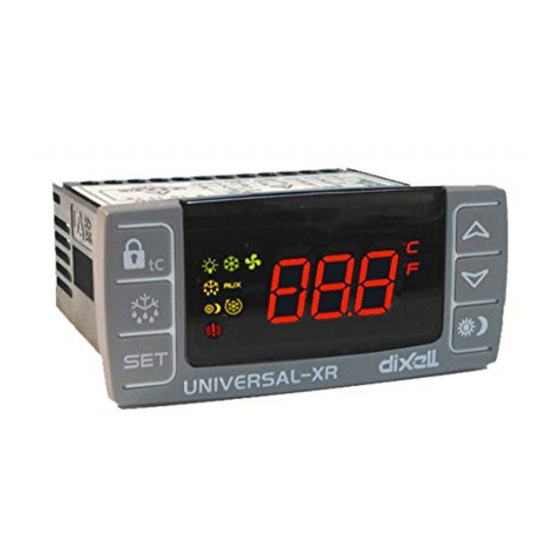
Digital controller with defrost management
XR40CX
CONTENTS
1.
GENERAL WARNING__________________________________________________________1
2.
GENERAL DESCRIPTION ______________________________________________________1
3.
CONTROLLING LOADS________________________________________________________1
4.
FRONT PANEL COMMANDS ___________________________________________________1
5.
MAX & MIN TEMPERATURE MEMORIZATION _____________________________________1
6.
MAIN FUNCTIONS ____________________________________________________________1
7.
PARAMETERS _______________________________________________________________2
8.
DIGITAL INPUT (ENABLED WITH P3P = N)________________________________________3
9.
TTL SERIAL LINE – FOR MONITORING SYSTEMS _________________________________3
10. X-REP OUTPUT – OPTIONAL___________________________________________________3
11. INSTALLATION AND MOUNTING ________________________________________________3
12. ELECTRICAL CONNECTIONS __________________________________________________3
13. HOW TO USE THE HOT KEY ___________________________________________________3
14. ALARM SIGNALS _____________________________________________________________3
15. TECHNICAL DATA ____________________________________________________________3
16. CONNECTIONS ______________________________________________________________3
17. DEFAULT SETTING VALUES ___________________________________________________4
1. GENERAL WARNING
1.1 PLEASE READ BEFORE USING THIS MANUAL
This manual is part of the product and should be kept near the instrument for easy and quick
reference.
The instrument shall not be used for purposes different from those described hereunder. It
cannot be used as a safety device.
Check the application limits before proceeding.
Dixell Srl reserves the right to change the composition of its products, even without notice,
ensuring the same and unchanged functionality.
1.2
SAFETY PRECAUTIONS
Check the supply voltage is correct before connecting the instrument.
Do not expose to water or moisture: use the controller only within the operating limits avoiding
sudden temperature changes with high atmospheric humidity to prevent
condensation
Warning: disconnect all electrical connections before any kind of maintenance.
Fit the probe where it is not accessible by the End User. The instrument must not be opened.
In case of failure or faulty operation send the instrument back to the distributor or to "Dixell S.r.l."
(see address) with a detailed description of the fault.
Consider the maximum current which can be applied to each relay (see Technical Data).
Ensure that the wires for probes, loads and the power supply are separated and far enough
from each other, without crossing or intertwining.
In case of applications in industrial environments, the use of mains filters (our mod. FT1) in
parallel with inductive loads could be useful.
2. GENERAL DESCRIPTION
Model XR40CX, format 32 x 74 mm, is microprocessor based controller, suitable for applications on
medium or low temperature refrigerating units. It has 2 relay outputs to control compressor and
defrost, which can be either electrical or reverse cycle (hot gas). It is also provided with three NTC or
PTC probe inputs, the first one for temperature control, the second one, to be located onto the
evaporator, to control the defrost termination temperature, the third one, optional, to connect to the
HOT KEY terminals to signal the condenser temperature alarm or to display a temperature. The
digital input can operate as fourth temperature probe.
The HOT KEY output allows to connect the unit, by means of the external module XJ485-CX, to a
network line ModBUS-RTU compatible such as the dIXEL monitoring units of X-WEB family. It
allows to program the controller by means the HOT KEY programming keyboard.
The instrument is fully configurable through special parameters that can be easily programmed
through the keyboard.
3. CONTROLLING LOADS
3.1 COMPRESSOR
The regulation is performed according to
the temperature measured by the
thermostat
probe
with a positive
differential from the set point: if the
temperature increases and reaches set
point plus differential the compressor is
started and then turned off when the
temperature reaches the set point value
again.
In case of fault in the thermostat probe the start and stop of the compressor are timed through
parameters "COn" and "COF".
3.2 DEFROST
Two defrost modes are available through the "tdF" parameter: defrost through electrical heater (tdF =
EL) and hot gas defrost (tdF = in). Other parameters are used to control the interval between
defrost cycles (IdF), its maximum length (MdF) and two defrost modes: timed or controlled by the
evaporator's probe (P2P).
At the end of defrost dripping time is started, its length is set in the FSt parameter. With FSt =0 the
dripping time is disabled.
1592020040 XR40CX GB m&M r1.1 22.06.2012
formation of
Temper.
SET
Compr.
ON
4. FRONT PANEL COMMANDS
: To display target set point; in programming mode it selects a parameter or confirm an
operation.
(DEF) To start a manual defrost
(UP): To see the max. stored temperature; in programming mode it browses the parameter
codes or increases the displayed value.
(DOWN) To see the min stored temperature; in programming mode it browses the parameter
codes or decreases the displayed value.
To switch the instrument off, if onF = oFF.
Not enabled.
KEY COMBINATIONS:
+
+
+
4.1 USE OF LEDS
Each LED function is described in the following table.
LED
MODE
ON
Flashing
ON
Flashing
ON
ON
ON
°C/°F ON
°C/°F Flashing
5. MAX & MIN TEMPERATURE MEMORIZATION
5.1 HOW TO SEE THE MIN TEMPERATURE
Press and release the n key.
1.
2.
The "Lo" message will be displayed followed by the minimum temperature recorded.
By pressing the n key again or by waiting 5s the normal display will be restored.
3.
5.2 HOW TO SEE THE MAX TEMPERATURE
Press and release the o key.
1.
2.
The "Hi" message will be displayed followed by the maximum temperature recorded.
By pressing the o key again or by waiting 5s the normal display will be restored.
3.
5.3 HOW TO RESET THE MAX AND MIN TEMPERATURE RECORDED
1.
Hold press the SET key for more than 3s, while the max. or min temperature is displayed. (rSt
message will be displayed)
2.
To confirm the operation the "rSt" message starts blinking and the normal temperature will be
displayed.
6. MAIN FUNCTIONS
6.1 HOW TO SEE THE SETPOINT
Time
display the probe value again.
6.2 HOW TO CHANGE THE SETPOINT
1.
Push the SET key for more than 2 seconds to change the Set point value;
2.
The value of the set point will be displayed and the "°C" or "°F" LED starts blinking;
To change the Set value push the o or n arrows within 10s.
3.
4.
To memorise the new set point value push the SET key again or wait 10s.
6.3 HOW TO START A MANUAL DEFROST
6.4 HOW TO CHANGE A PARAMETER VALUE
To change the parameter's value operate as follows:
XR40CX
To lock & unlock the keyboard.
To enter in programming mode.
To return to the room temperature display.
FUNCTION
Compressor enabled
Anti-short cycle delay enabled
Defrost enabled
Drip time in progress
An alarm is occurring
Continuous cycle is running
Energy saving enbled
Measurement unit
Programming phase
1.
Push and immediately release the SET key: the display will show the Set
point value;
2.
Push and immediately release the SET key or wait for 5 seconds to
Push the DEF key for more than 2 seconds and a manual defrost will start.
1/4

Related Manuals for Emerson Dixell XR40CX


Summary of Contents for Emerson Dixell XR40CX
- Page 1 4. FRONT PANEL COMMANDS Digital controller with defrost management XR40CX CONTENTS GENERAL WARNING__________________________________________________________1 GENERAL DESCRIPTION ______________________________________________________1 CONTROLLING LOADS________________________________________________________1 FRONT PANEL COMMANDS ___________________________________________________1 MAX & MIN TEMPERATURE MEMORIZATION _____________________________________1 MAIN FUNCTIONS ____________________________________________________________1 : To display target set point; in programming mode it selects a parameter or confirm an PARAMETERS _______________________________________________________________2 operation.
- Page 2 1. Enter the Programming mode by pressing the Set + n keys for 3s (the “°C” or “°F” LED starts DISPLAY blinking). CF Temperature measurement unit: °C=Celsius; °F=Fahrenheit. WARNING: When the 2. Select the required parameter. Press the “SET” key to display its value measurement unit is changed the SET point and the values of the parameters Hy, LS, US, Ot, 3.
- Page 3 power connections. Do not exceed the maximum current allowed on each relay, in case of heavier OTHER loads use a suitable external relay. Adr Serial address (1÷244): Identifies the instrument address when connected to a ModBUS compatible monitoring system. 12.1 PROBE CONNECTION PbC Type of probe: it allows to set the kind of probe used by the instrument: PbC = PBC probe, ntc = NTC probe.
- Page 4 16.1 XR40CX – 8A COMPRESSOR 17. DEFAULT SETTING VALUES Label Name Range °C/°F Set Set point LS÷US -5.0 - - - 9 10 11 12 Hy Differential 0,125.5°C/ 1 255°F LS Minimum set point -50.0 -50°CSET/-58°FSET 8(3)A250V 8(3)A250V US Maximum set point SET110°C/ SET ...