Emerson Dixell XR75CX Series Installation And Operation Manual
Digital controller for medium-low temperature refrigeration applications
Hide thumbs
Also See for Dixell XR75CX Series:
- Installation and operation manual (36 pages) ,
- Installation and operation manual (25 pages)

Related Manuals for Emerson Dixell XR75CX Series


Summary of Contents for Emerson Dixell XR75CX Series
- Page 1 XR75CX Digital Controller for Medium-Low Temperature Refrigeration Applications Installation and Operation Manual 026-1210 Rev 4...
- Page 3 Emerson 1065 Big Shanty Road NW, Suite 100 Kennesaw, GA 30144 USA 770-425-2724 • www.emerson.com...
-
Page 5: Table Of Contents
Table of Contents 1 INTRODUCTION................................1 1.1. G ..............................1 ENERAL ARNING 2 OVERVIEW ................................... 1 2.1. G ..............................1 ENERAL ESCRIPTION 2.2. O ................................. 1 RDERING 3 CONTROLLING LOADS ............................2 3.1. C ................................2 OMPRESSOR 3.2. D ..................................2 EFROST 3.3. - Page 6 8.3. P 2F=PAL) ........................... 13 RESSURE WITCH 8.4. D ) ........................13 WITCH NPUT OR I 8.5. S EF)..........................13 TART EFROST OR I 8.6. S 2F=AUS) ......................13 WITCH THE UXILIARY ELAY 8.7. I 2F=H ) ..............13 NVERSION OF THE IND OF CTION EATING...
-
Page 7: Introduction
XR75CX - XR75CX-4C6F3B - • In case of failure or faulty operation, send the 318-6030 110VAC X0LG3OEUB4NA-000 device back to the distributor or to Emerson (see XR75CX - XR75CX-5C6F3B - address) with a detailed description of the fault. 318-6031 230VAC X0LG3OEUB5NA-000 •... -
Page 8: Controlling Loads
Controlling Loads 3.3. Control of Evaporator Fans The fan control mode is selected by means of the FnC 3.1. Compressor parameter: • FnC = C_n: fans will switch ON and OFF with the The regulation is performed according to the temperature compressor and not run during defrost. -
Page 9: Light Relay
3.4.1. Light Relay When oA2 = Lig, the relay 1-2 operates as a light. 3.4.2. Auxiliary Relay — oA2=AUS a. Relay Activation By Digital Input 2 (oA2 = AUS, i2F = AUS) When oA2 = AUS and i2F = AUS, the relay 1-2 is switched ON and OFF by the digital input. -
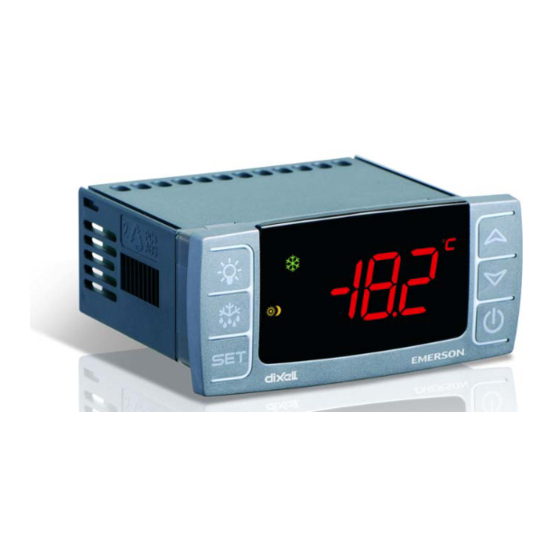
Page 10: Front Panel Commands
Front Panel Locks/Unlocks the keyboard Commands To enter programming mode Returns to room temperature display Table 4-1 - XR75CX Front Panel Keys and Functions 4.2. Use of LEDS Each LED function is described in Table 4-2: Mode Function Compressor enabled Figure 4-1 - XR75CX Front Panel Flashing Anti-short cycle delay enabled... -
Page 11: Max And Min Temperature Memorization
Max and Min Temperature Memorization 5.1. How to See the MIN Temperature Press and release the DOWN button. The Lo message will be displayed followed by the minimum temperature recorded. By pressing the DOWN button again or by waiting five seconds, the normal display will be restored. -
Page 12: Main Functions
Main Functions Use the UP or DOWN buttons to change its value. Press SET to store the new value and move to the next parameter. To exit: Press the SET + UP buttons or wait 15 seconds without pressing a key. 6.1. -
Page 13: How To Move A Parameter From The Hidden Menu To The First Level And Vice Versa
6.5.2. How to Move a Parameter 6.9. The Continuous Cycle From the Hidden Menu To the First Level and Vice Versa When a defrost is not in progress, it can be activated by Each parameter present in the Hidden Menu (Pr2) can be pressing and holding the UP button for about 3 seconds. -
Page 14: Parameters
Parameters Code Parameter Function REGULATION (0.1 to 25.5°C; 1 to 45°F) Intervention differential for setpoint. Differential Compressor Cut IN is Set Point + differential (HY). Compressor Cut OUT is when the temperature reaches the setpoint. (-50°C to SET; -58°F to SET) Sets the minimum value for the Minimum setpoint setpoint. - Page 15 Code Parameter Function (°C; °F) °C = Celsius; °F = Fahrenheit. CAUTION: When the measurement unit is changed the SET Temperature measurement unit point and the values of the parameters HY, LS, US, ot, ALU and ALL have to be checked and modified (if necessary). Resolution (for °C) (in=1°C;...
- Page 16 Code Parameter Function (C-n; o-n; C-Y; o-Y) C-n = runs with the compressor, OFF during defrost; o-n = continuous mode, OFF during defrost; C- Fans operating mode Y = runs with the compressor, ON during defrost; o-Y = continuous mode, ON during defrost. (0 to 255min) Interval between end of defrost and evaporator Fans delay after defrost fans start.
- Page 17 Code Parameter Function (ALL to 110°C; ALL to 230°F) When this temperature is MAXIMUM temperature alarm reached the alarm is enabled, after the ALd delay time. (-50°C to ALU; -58 to ALU) When this temperature is reached Minimum temperature alarm the alarm is enabled, after the ALd delay time.
- Page 18 Code Parameter Function (dor; dEF) dor = door switch function; dEF = activation of a Digital input configuration (18-20) defrost cycle (oP; CL) oP = the digital input is activated by opening the Second digital input polarity (18-19) contact; CL = the digital input is activated by closing the contact (EAL;...
-
Page 19: Digital Inputs
Digital Inputs 8.5. Start Defrost (i1F or i2F=dEF) The first digital input 18-20 is enabled with P3P = n.With A defrost will start if the right conditions exist. After the P3P = n and i1F = i2F, the second digital input is disabled. defrost is finished, normal regulation will restart only if the The free voltage digital inputs are programmable by the i1F digital input is disabled;... -
Page 20: Rs485 Serial Line (For Monitoring Systems)
RS485 Serial Line 10 X-REP Output (For Monitoring (Optional) Systems) Optionally, an X-REP can be connected to the controller through the dedicated connector. The RS485 serial line allows the controller to connect to a monitoring system (MODBUS-RTU compatible) such as the X-WEB500/3000/300. -
Page 21: Installation And Mounting
11 Installation and 12 Electrical Mounting Connections The device is provided with screw terminal block to connect cables with a cross section up to 2.5 mm . Before connecting cables verify that the power supply complies with the device’s requirements. Separate the probe cables from the power supply cables, from the outputs and the ... -
Page 22: How To Use The Hot Key
13 How to Use the followed by End at the end of the data transfer phase if the controller is programmed Hot Key correctly. After 10 seconds the controller will restart and work with the new parameters. Remove the Hot Key. 13.1. -
Page 23: Alarm Signals
14 Alarm Signals 14.2. Alarm Recovery Probe alarms P1, P2, P3, and P4 start some seconds after the fault in the related probe; they automatically stop some Message Cause Outputs seconds after the probe restarts normal operation. Check connections before replacing the probe. Compressor output Room probe failure acc. -
Page 24: Specifications
15 Specifications Case: Front: 32 mm x 74 mm Dimensions Depth: 60 mm Panel Mount: 71 mm x 29 mm panel cut-out Housing Self extinguishing ABS Protection IP 20 Frontal Protection IP65 Connections Screw terminal block ≤ 2.5 mm wiring 24VAC ±10%... - Page 25 Relative Humidity 20 to 85% (no condensing) NTC-EU probe (10k ±1%, =3435): -40 to 110°C (-40 to 230°F) Measuring and Regulation Range NTC-US probe (xxk ±y%, =????): -40 to 110°C (-40 to 230°F) Resolution 0.1°C or 1°C or 1°F (selectable) Accuracy ...
-
Page 26: Connections
16 Connections Figure 16-1 - XR75CX Connections 20 • XR75CX I&O Manual 026-1210 Rev 4... -
Page 27: E2 Modbus Network Wiring
17 E2 MODBUS Network Wiring • Connect the MODBUS Network to the RS485 Connector on the E2 PIB board (Belden 8641 recommended). • Note to wire the RS485 +/- polarity at the E2 in the reverse of the XR75CX devices. •... -
Page 28: Ect Modbus Networking To E2S
(PIB) Below) Serial Device RS485 COM Ports Connecting a XR75CX controller to an E2 requires the E2 to be version 2.84 or above. Contact Emerson for upgrade COM2 COM6 COM4 information if the controller is a version before 2.84. An E2 has up to three COM ports that can be assigned for... -
Page 29: E2 Setup Of Devices
as the I/O network, you cannot connect MODBUS devices rate.) to COM2. Ensure your E2 is configured in E2 General • Data Size - Leave this field at the default value (8). Services (, Serial tab) to enable COM4 or COM6. -
Page 30: Wiring Types
For MODBUS network wiring of XR75CX controllers to Figure 18-7 - List of MODBUS Devices E2, Belden #8641 (Emerson P/N 135-8641) is the recommended wire type to use. 7. Repeat Steps 5 and 6 until each device has a name and address. -
Page 31: Modbus Termination Blocks
If the recommended cable is not available in your area, be sure the wiring meets or exceeds the following specs: Shielded? Conductor Type Twisted Pair Gauge 18 - 24 AWG Capacitance between 31 pF/ft or less signal wires (9.45 m) or less Capacitance between 59 pF/ft or less... -
Page 32: Default Setting Values
19 Default Setting Values Label Name Range Value Level [-5.0°C] Setpoint LS to US - - - [23°F] [0.1 to 25.5°C] [2.0°C] Differential [1 to 255°F] [2°F] [-50°C to SET] [-50.0°C] Minimum setpoint [-58°F to SET] [-58°F] [SET to 110°C] [110.0°C] Maximum setpoint [SET to 230°F]... - Page 33 Label Name Range Value Level [-50 to 50°C] [8°C] Defrost termination temperature [-50 to 122°F] [46°F] Interval between defrost cycles 1 to 120 hours (Maximum) length for defrost 0 to 255 min Start defrost delay 0 to 99 min Displaying during defrost rt, it, SEt, DEF MAX display delay after defrost 0 to 255 min...
- Page 34 Label Name Range Value Level [-50 to 110°C] [110°C] Condenser for high temperat. alarm [-58 to 230°F] [230°F] Differential for condenser [0.1°C to 25.5°C] [5°C] temperature alarm recovery [1°F to 45°F] [5°F] Condenser temperature alarm delay 0 to 254 min, 255=nU Delay of cond.
- Page 35 Label Name Range Value Level Third probe display Fourth probe display Real set actual set Software release Map code Table 19-1- XR75CX Default Setting Values ( Only for XR75CX with X-REP output) MODBUS Termination Blocks Default Setting Values • 29...
-
Page 36: Appendix A - Alternate Modbus Com Wiring Method For E2, Xr, Xm, And Xev Devices
COM2 supports two network segments: one on connector RS485-1A, and the second on connector RS485-1B. For information on the maximum recommended number of XR, XM, and XEV devices for each network segment (load and bandwidth calculations), contact Emerson Technical Support at 770-425-2724. 30 • XR75CX I&O Manual 026-1210 Rev 4... - Page 37 Figure A -1 - MODBUS Com Wiring Diagram MODBUS Termination BlocksAppendix A - Alternate MODBUS COM Wiring Method for E2, XR, XM, and XEV Devic- es • 31...
- Page 39 Emerson Climate Technologies Retail Solutions, Inc. and/or its affiliates (collectively “Emerson”), reserves the right to modify the designs or specifications of such products at any time without notice. Emerson does not assume responsibility for the selection, use or maintenance of any product. Responsibility for proper selection, use and maintenance of any product remains solely with the purchaser and end-user.