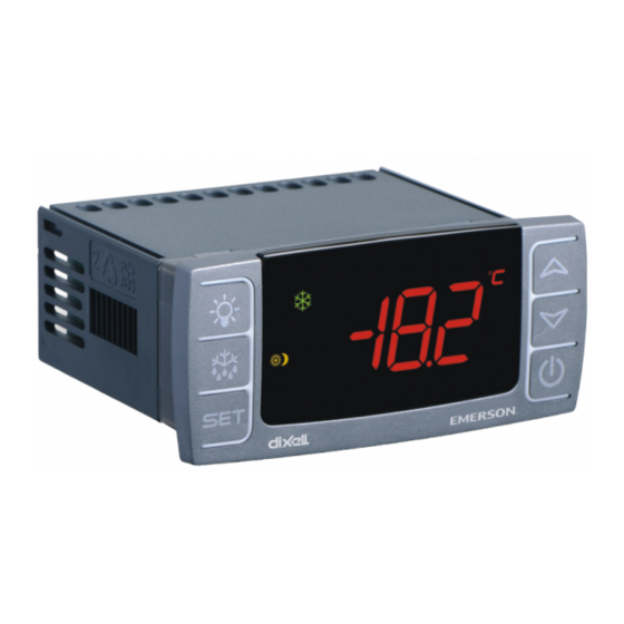
Emerson XR75CX Installation And Operation Manual
Digital controller for medium-low temperature refrigeration applications
Hide thumbs
Also See for XR75CX:
- Installation and operation manual (39 pages) ,
- Installation and operation manual (25 pages)

Related Manuals for Emerson XR75CX


Summary of Contents for Emerson XR75CX
- Page 1 026-1210 Rev 0 09-FEB-2011 XR75CX Digital Controller for Medium-Low Temperature Refrigeration Applications Installation and Operation Manual...
- Page 3 Retail Solutions 3240 Town Point Drive NW Suite 100 Kennesaw, GA 30144 USA Phone: 770-425-2724 Fax: 770-425-9319 ALL RIGHTS RESERVED. The information contained in this manual has been carefully checked and is believed to be accurate. However, Com- puter Process Controls, Inc. assumes no responsibility for any inaccuracies that may be contained herein. In no event will Computer Process Controls, Inc.
-
Page 5: Table Of Contents
Table of Contents 1 INTRODUCTION................................1 1.1. G ..............................1 ENERAL ARNING 2 OVERVIEW ................................... 1 2.1. G ..............................1 ENERAL ESCRIPTION 2.2. O ................................. 1 RDERING 3 CONTROLLING LOADS ............................2 3.1. C ................................2 OMPRESSOR 3.2. D ..................................2 EFROST 3.3. - Page 6 18.1.1. Set Up Network Ports............................23 18.1.2. Add and Connect the Device ..........................24 18.2. W ................................25 IRING YPES 18.3. MODBUS T ........................... 26 ERMINATION LOCKS 19 DEFAULT SETTING VALUES..........................27 ii • XR75CX I&O Manual 026-1210 Rev 0 09-FEB-2011...
-
Page 7: Introduction
1.1. General Warning 2.1. General Description Please read the following safety precautions and Model XR75CX (32 mm x 74 mm) is a micropro- warnings before using this manual: cessor based controller, suitable for applications on medium or low temperature ventilated refrigeration units. -
Page 8: Controlling Loads
(P2P). At the end of defrost dripping time is started, its duration is set in the Fdt parameter. With Fdt=0, the dripping time is disabled. 2 • XR75CX I&O Manual 026-1210 Rev 0 09-FEB-2011... -
Page 9: Light Relay Configuration (Par Oa3; Term. 1-4)
oA3 cut out = SEt 3.4. Light Relay 3.4.5. Alarm Relay Configuration (PAR When oA3 = ALr relay 1-4 operates as an alarm relay. It is activated every time an alarm occurs. Its oA3; TERM. 1-4) status depends on the tbA parameter: if tbA = y, the relay is silenced by pressing any key. -
Page 10: Front Panel Commands
Switches the light ON and OFF, if oA1 = Lig Locks/Unlocks the keyboard To enter programming mode Returns to room temperature display Table 4-1 - XR75CX Front Panel Keys and Functions 4.2. Use of LEDS Figure 4-1 - XR75CX Front Panel Each LED function is described in Table 4-2:... -
Page 11: Max And Min Temperature Memorization
Max and Min Temperature Memorization 5.1. How to See the MIN Temperature Press and release the DOWN arrow key. The Lo message will be displayed followed by the minimum temperature recorded. By pressing the DOWN arrow key again or by waiting five seconds, the normal display will be restored. -
Page 12: Main Functions
The value of the setpoint will be displayed Enter the Programming mode by pressing the and the °C or °F LED starts blinking. SET + DOWN arrow keys for three (3) sec- 6 • XR75CX I&O Manual 026-1210 Rev 0 09-FEB-2011... -
Page 13: How To Move A Parameter From The Hidden Menu And Vice Versa
onds (the °C or °F LED starts blinking). 6.8. How to Lock the Immediately release the keys, then push the SET + DOWN arrow keys again for more Keyboard than seven (7) seconds. The Pr2 label will be displayed immediately followed by the Hy parameter: You are now in the Hidden Menu. -
Page 14: Parameters
(0 to 255 min) faulty probe Time during which the compressor is OFF in case of faulty thermostat probe. When CoF = 0, compressor is always active. Table 7-1 - List of Parameters 8 • XR75CX I&O Manual 026-1210 Rev 0 09-FEB-2011... - Page 15 Code Parameter Function DISPLAY Temperature measurement unit °C = Celsius °F = Fahrenheit (CAUTION! When the measurement unit is changed, the setpoint and the values of the parameters Hy, LS, US, ot, ALU and ALL have to be checked and modified if neces- sary).
- Page 16 When ACH = CL AUX Cut in is SAA + SHy; AUX Cut out is SAA When ACH = Ht AUX Cut in is SAA - SHy; AUX Cut out is SAA Table 7-1 - List of Parameters 10 • XR75CX I&O Manual 026-1210 Rev 0 09-FEB-2011...
- Page 17 Code Parameter Function Probe selection for auxiliary nP = no probe, the auxiliary relay is switched only by the digital input P1 = Probe 1 (thermostat probe) P2 = Probe 2 (evaporator probe) P3 = Probe 3 (display probe) P4 = Probe 4 Auxiliary relay OFF during de- n = the auxiliary relay operates during defrost frost...
- Page 18 Sets the current day of the week. First weekly holiday (Sun to Set the first day of the week that follows the holiday times. not used) Table 7-1 - List of Parameters 12 • XR75CX I&O Manual 026-1210 Rev 0 09-FEB-2011...
- Page 19 Code Parameter Function Second weekly holiday (Sun to Set the second day of the week that follows the holiday times. not used) NOTE: Hd, Hd2 can be set also as “not used” value. TO SET ENERGY SAVING TIMES (ONLY FOR MODELS WITH RTC) Energy Saving cycle start dur- (0 to 23 hr 50 min) ing workdays...
-
Page 20: Digital Inputs
= yES. The alarm stops as soon as the ex- 14 • XR75CX I&O Manual 026-1210 Rev 0 09-FEB-2011... -
Page 21: Digital Inputs Polarity
8.11. Digital Inputs Polarity The digital input polarity depends on the i1P and i2P parameters. • i1P or i2P = CL: the input is activated by closing the contact. • i1P or i2P = oP: the input is activated by opening the contact Digital Inputs Polarity Digital Inputs •... -
Page 22: Rs485 Serial Line (For Monitoring Systems)
MODBUS-RTU compat- ible such as the X-WEB500/3000/300. Figure 10-1 - X-REP Output To connect the X-REP to the controller, the fol- lowing connectors must be used: CAB-51F(1m), CAB-52F (2m), CAB-55F (5m). 16 • XR75CX I&O Manual 026-1210 Rev 0 09-FEB-2011... -
Page 23: Installation And Mounting
12.1. Probe Connection The probes should be mounted with the bulb up- Figure 11-1 - Installation and Mounting of XR75CX wards to prevent damages due to casual liquid infiltra- tion. It is recommended the thermostat probe be placed away from air streams to measure the average room temperature correctly. -
Page 24: How To Use The Hot Key
Key is downloaded into the controller memo- ry, the doL message is blinking followed a by flashing End LED. After 10 seconds the controller will restart and work with the new parameters. Remove the Hot Key. 18 • XR75CX I&O Manual 026-1210 Rev 0 09-FEB-2011... -
Page 25: Alarm Signals
14 Alarm Signals 14.2. Alarm Recovery Probe alarms P1, P2, P3, and P4 start some sec- onds after the fault in the related probe; they automat- Message Cause Outputs ically stop some seconds after the probe restarts Room probe failure Compressor output acc. -
Page 26: Specifications
Measuring and Regulation Range PT1000 probe: -100 to 150°C (-148 to 302°F) Resolution 0.1°C or 1°C or 1°F (selectable) Accuracy ±0.7°C ±1 digit (ambient temperature 25°C) Table 15-1 - XR75CX Specifications 20 • XR75CX I&O Manual 026-1210 Rev 0 09-FEB-2011... -
Page 27: Connections
16 Connections Figure 16-1 - XR75CX Connections Other Messages Connections • 21... -
Page 28: E2 Modbus Network Wiring
18 terminal. • Terminate the end of the MODBUS network at the last XR75CX device on the daisy chain with the MODBUS ter- mination block (P/N 535-2711), or by connecting a 150 ohm resistor between the MODBUS +/- terminals. -
Page 29: Ect Modbus Networking To E2S
E2 Enclosure (Right Side) E2 Modem/Expansion COM6 COM Card Mounted Above PIB RS232 Connecting a XR75CX controller to an E2 re- quires the E2 to be version 2.84 or above. Contact Re- COM3 COM1 Plug-In Modem tail Solutions for upgrade information if the controller... -
Page 30: Add And Connect The Device
18.1.2.Add and Connect the Device To enable communications between E2 and the XR75CX units, the devices must be added and ad- dressed in E2. Log in to the E2 with Level 4 access. Figure 18-5 - Network Summary Screen ... -
Page 31: Wiring Types
E2 for communica- the XR75CX address set up through the front tion. Replace the device with a new one or a device that has the latest version of firmware on it. -
Page 32: Modbus Termination Blocks
18.3. MODBUS Termination Blocks Because the XR75CX device has no on-board means of termination, use the MODBUS termination block (P/N 535-2711) for termination that can be wired to the end of the cable segment using the three- pin connector. Wire the two signal wires to the out-... -
Page 33: Default Setting Values
Defrost delay after fast freezing 0 to 23 hr and 50’ Table 19-1 - Default Setting Values ( Only for models with real time clock (RTC), Only for XR75CX with X-REP output) MODBUS Termination Blocks Default Setting Values • 27... - Page 34 AUS - Htr - FAn - HdF - onF Digital input alarm delay (18-20) 0 to 255 min Table 19-1 - Default Setting Values ( Only for models with real time clock (RTC), Only for XR75CX with X-REP output) 28 • XR75CX I&O Manual 026-1210 Rev 0 09-FEB-2011...
- Page 35 Fourth probe display Real set actual set Software release Map code Table 19-1 - Default Setting Values ( Only for models with real time clock (RTC), Only for XR75CX with X-REP output) MODBUS Termination Blocks Default Setting Values • 29...