Table of Contents
Table of Contents

Related Manuals for Epson LS3-401 series


Summary of Contents for Epson LS3-401 series
- Page 1 SCARA ROBOT LS series MANIPULATOR MANUAL Rev.10 EM16XR3299F...
- Page 3 SCARA ROBOT LS series Manipulator Manual Rev.10 Copyright 2011-2016 SEIKO EPSON CORPORATION. All rights reserved.
- Page 4 FOREWORD Thank you for purchasing our robot products. This manual contains the information necessary for the correct use of the manipulator. Please carefully read this manual and other related manuals before installing the robot system. Keep this manual handy for easy access at all times. WARRANTY The Manipulator and its optional parts are shipped to our customers only after being subjected to the strictest quality controls, tests, and inspections to certify its compliance...
- Page 5 TRADEMARKS Microsoft, Windows, and Windows logo are either registered trademarks or trademarks of Microsoft Corporation in the United States and/or other countries. Other brand and product names are trademarks or registered trademarks of the respective holders. NOTICE No part of this manual may be copied or reproduced without authorization. The contents of this manual are subject to change without notice.
- Page 6 Regarding battery disposal The crossed out wheeled bin label that can be found on your product indicates that this product and incorporated batteries should not be disposed of via the normal household waste stream. To prevent possible harm to the environment or human health please separate this product and its batteries from other waste streams to ensure that it can be recycled in an environmentally sound manner.
- Page 7 Ver.3.0.*.* Before Ver.5.4.0 EPSON RC+ 5.0 Ver.5.4.1 or later OK: Compatible All functions of the EPSON RC+ 5.0 and the Controller are available. !!!: Compatible Connection is OK. We recommend using EPSON RC+5.0 Ver. 5.4.1 or later. Controller firmware update cannot be executed.
- Page 8 Ver.7.0.2.0 or later Before Ver.7.0.1 EPSON RC+ 7.0 Ver.7.0.2 or later OK: Compatible All functions of the EPSON RC+ 7.0 and the Controller are available. !!!: Compatible Connection is OK. We recommend using EPSON RC+ 7.0 Ver. 7.0.2 or later.
- Page 9 Setting by Using Software This manual contains setting procedures by using software. They are marked with the following icon. EPSON Figures in this Manual The figures of manipulators indicated in this manual are basically Standard-model Manipulator. Unless special instruction is provided, the specifications of Standard-model and Cleanroom-model are the same.
- Page 10 LS Rev.10 viii...
-
Page 11: Table Of Contents
TABLE OF CONTENTS Setup & Operation 1. Safety 1.1 Conventions....................3 1.2 Design and Installation Safety ..............4 1.2.1 Strength of the Ball Screw Spline ..........5 1.3 Operation Safety ..................6 1.4 Emergency Stop ..................8 1.4.1 Controller Firmware Ver. 7.0.2.3 or earlier ........8 1.4.2 Controller Firmware Ver. - Page 12 TABLE OF CONTENTS 5. Motion Range 5.1 Motion Range Setting by Pulse Range (for All Joints) ......54 5.1.1 Max. Pulse Range of Joint #1 ............. 55 5.1.2 Max. Pulse Range of Joint #2 ............. 55 5.1.3 Max. Pulse Range of Joint #3 ............. 56 5.1.4 Max.
- Page 13 TABLE OF CONTENTS 6. Arm #2 6.1 Replacing Joint #2 Motor ............... 99 6.2 Replacing Joint #2 Reduction Gear Unit ..........103 7. Arm #3 7.1 Replacing Joint #3 Motor ..............108 7.2 Replacing the Timing Belt ..............112 7.3 Replacing the Brake ................116 7.4 Checking the Timing Belt Tension (Z Belt) ...........
- Page 14 TABLE OF CONTENTS LS Rev.10...
-
Page 15: Setup & Operation
Setup & Operation This volume contains information for setup and operation of the LS series Manipulators. Please read this volume thoroughly before setting up and operating the Manipulators. -
Page 17: Safety
Setup & Operation 1. Safety 1. Safety Installation and transportation of manipulators and robotic equipment shall be performed by qualified personnel and should conform to all national and local codes. Please read this manual and other related manuals before installing the robot system or before connecting cables. -
Page 18: Design And Installation Safety
The following items are safety precautions for design personnel: ■ Personnel who design and/or construct the robot system with this product must read the Safety chapter in the EPSON RC+ User’s Guide to understand the safety requirements before designing and/or constructing the robot system. -
Page 19: Strength Of The Ball Screw Spline
Setup & Operation 1. Safety 1.2.1 Strength of the Ball Screw Spline If a load exceeding the allowable value is applied to the ball screw spline, it may not work properly due to deformation or breakage of the shaft. If the ball screw spline is applied the load exceeding the allowable value, it is necessary to replace the ball screw spline unit. -
Page 20: Operation Safety
Setup & Operation 1. Safety 1.3 Operation Safety The following items are safety precautions for qualified Operator personnel: ■ Please carefully read the Safety-related Requirements in the Safety chapter of the Safety and Installation manual before operating the robot system. Operating the robot system without understanding the safety requirements is extremely hazardous and may result in serious bodily injury and/or severe equipment damage to the robot system. - Page 21 Setup & Operation 1. Safety ■ Whenever possible, only one person should operate the robot system. If it is necessary to operate the robot system with more than one person, ensure that all people involved communicate with each other as to what they are doing and take all necessary safety precautions.
-
Page 22: Emergency Stop
Setup & Operation 1. Safety 1.4 Emergency Stop Emergency stop motions of the Manipulator vary depending on the controller firmware. See the section for the Controller firmware of your Controller. 1.4.1 Controller Firmware Ver. 7.0.2.3 or earlier If the Manipulator moves abnormally during operation, immediately press the Emergency Stop switch. - Page 23 Setup & Operation 1. Safety For details of the Safeguard system, refer to the following manuals. EPSON RC+ User’s Guide 2. Safety - Installation and Design Precautions - Safeguard System Safety and Installation 2.6 Connection to EMERGENCY Connector To check brake problems, refer to the following manuals.
-
Page 24: Controller Firmware Ver. 7.0.2.4 Or Later
For the Safeguard system, do not use the circuit for E-STOP. For details of the Safeguard system, refer to the following manuals. EPSON RC+ User’s Guide 2. Safety - Installation and Design Precautions - Safeguard System Safety and Installation 2.6 Connection to EMERGENCY Connector... - Page 25 Setup & Operation 1. Safety To check brake problems, refer to the following manuals. Manipulator Manual Maintenance 2.1.2 Inspection Point - Inspection While the Power is ON (Manipulator is operating) Safety and Installation 5.1.1 Manipulator - Inspection While the Power is ON (Manipulator is operating) Free running distance in emergency The operating Manipulator cannot stop immediately after the Emergency Stop switch is pressed.
-
Page 26: Emergency Movement Without Drive Power
Setup & Operation 1. Safety 1.5 Emergency Movement Without Drive Power When the system is placed in emergency mode, push the arm or joint of the Manipulator by hand as shown below: Arm #1 Push the arm by hand. Arm #2 Push the arm by hand. -
Page 27: Accels Setting For Cp Motions
Setup & Operation 1. Safety 1.6 ACCELS Setting for CP Motions To make the Manipulator move in CP motion, see the following and set ACCELS properly according to the tip load and the Z-axis height. NOTE Improper setting may cause following problems. ... -
Page 28: Warning Labels
Setup & Operation 1. Safety 1.7 Warning Labels The Manipulator has the following warning labels. The warning labels are attached around the locations where specific dangers exist. Be sure to comply with descriptions and warnings on the labels to operate and maintain the Manipulator safely. - Page 29 Setup & Operation 1. Safety (Opposite side) (Figure: LS3-401S) C (Arm Top Cover (Opposite side) (Figure: LS6-602S) LS Rev.10...
-
Page 30: Specifications
Setup & Operation 2. Specifications 2. Specifications 2.1 Features of LS series Manipulators The LS series Manipulators are advanced manipulators pursuing high speed and high cost-performance. The features of the LS series Manipulators are as follows: Resolver for the Position Detector It includes no electrical components;... -
Page 31: Model Number
Setup & Operation 2. Specifications 2.2 Model Number LS3-40 1 S Environment : Standard : Cleanroom Joint #3 stroke : 150 mm : Standard-Model : 120 mm : Cleanroom-Model (with bellows) : 200 mm : Standard-Model : 170 mm : Cleanroom-Model (with bellows) Arm length 40 : 400 mm 50 : 500 mm... -
Page 32: Part Names And Outer Dimensions
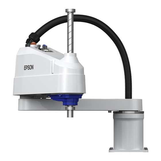
Setup & Operation 2. Specifications 2.3 Part Names and Outer Dimensions 2.3.1 LS3 Standard-Model LS3-401S LED lamp Joint #3 Brake release switch Arm #1 Arm #2 Base Shaft Fittings (black or blue) MT label Fittings (black or blue) for ø4 mm pneumatic tube (only for custom for ø6 mm specification) - Page 33 Setup & Operation 2. Specifications Standard-Model LS3-401S 90 or more Space for cables (*) indicates the stroke margin by mechanical stop. 1 mm flat Conical hole Ø3,90° Max.ø11 through hole shaft diameter Detail view from A mechanical stop diameter LS Rev.10...
- Page 34 Setup & Operation 2. Specifications Cleanroom-Model LS3-401C The following figures show the additional parts and specifications for Cleanroom-model when compared with the Standard-model in appearance. Upper bellows Exhaust port Lower bellows LS Rev.10...
- Page 35 Setup & Operation 2. Specifications Cleanroom-Model LS3-401C 90 or more (Space for cables) (*) indicates the stroke margin by mechanical stop. 1 mm flat Conical hole Ø3,90° Max.ø11 through hole φ16 h7 shaft diameter Detail view from A φ30 mechanical stop diameter LS Rev.10...
-
Page 36: Ls6
Setup & Operation 2. Specifications 2.3.2 LS6 Standard-Model LS6-**2S LED lamp Joint #3 Brake release switch Arm #1 Arm #2 Base Shaft Fittings (blue) Fittings (blue) for ø4 mm pneumatic tube MT label for ø6 mm (only for custom pneumatic tube specification) User connector (15-pin D-sub... - Page 37 Setup & Operation 2. Specifications Standard-Model LS6-**2S (*) indicates the stroke margin by mechanical stop. Detail view from A LS Rev.10...
- Page 38 Setup & Operation 2. Specifications Cleanroom-Model LS6-**2C The following figures show the additional parts and specifications for Cleanroom-model when compared with the Standard-model in appearance. Upper bellows Exhaust port Lower bellows LS Rev.10...
- Page 39 Setup & Operation 2. Specifications Cleanroom-Model LS6-**2C (*) indicates the stroke margin by mechanical stop. Detail view from A LS Rev.10...
-
Page 40: Specifications
Setup & Operation 2. Specifications 2.4 Specifications Item LS3-401* LS6-**2* 500 mm Arm #1, #2 400 mm 600 mm 700 mm Arm length 225 mm Arm #1 225 mm 325 mm 425 mm Arm #2 175 mm 275 mm 6150 mm/s Joints #1, #2 6000 mm/s 6800 mm/s... - Page 41 Setup & Operation 2. Specifications Item LS3-401* LS6-**2* SPEED 1 to (5) to100 ACCEL 1 to (10) to 120 SPEEDS 1 to (50) to 2000 Assignable Value ( ) Default values ACCELS 1 to (200) to 25000 FINE 0 to (1250) to 65000 WEIGHT 0,175 to (1,175) to 3,175 0,275 to (2,275) to 6,275...
-
Page 42: How To Set The Model
The custom specifications may require a different configuration procedure; check the custom specifications number described on the MT label and contact us when necessary. The Manipulator model can be set from software. Refer to the chapter Robot Configuration in the EPSON RC+ User’s Guide. LS Rev.10... -
Page 43: Environments And Installation
Setup & Operation 3. Environments and Installation 3. Environments and Installation 3.1 Environmental Conditions A suitable environment is necessary for the robot system to function properly and safely. Be sure to install the robot system in an environment that meets the following conditions: Item Conditions Ambient temperature... -
Page 44: Base Table
For environmental conditions regarding space when placing the Controller on the base table, refer to the Controller manual. ■ To ensure safety, a safeguard must be installed for the robot system. For details on the safeguard, refer to the EPSON RC+ User’s Guide. WARNING LS Rev.10... -
Page 45: Mounting Dimensions
Setup & Operation 3. Environments and Installation 3.3 Mounting Dimensions The maximum space described in figures shows that the radius of the end effector is 60 mm or less. If the radius of the end effector exceeds 60 mm, define the radius as the distance to the outer edge of maximum space. - Page 46 Setup & Operation 3. Environments and Installation Cleanroom-Model: LS3-401C Center of Joint #3 Maximum space Motion range Area limited by mechanical stop Base mounting face LS Rev.10...
-
Page 47: Ls6
Setup & Operation 3. Environments and Installation 3.3.2 LS6 Standard-Model: LS6-**2S LS6-702S LS6-602S LS6-502S Center of Joint #3 Motion range Maximum range Area limited by a mechanical stop Base mounting face LS6-502S LS6-602S LS6-702S Arm #1 + Arm #2 length [mm] Arm #1 length [mm] Arm #2 length [mm] Joint #1 motion angle [deg.]... - Page 48 Setup & Operation 3. Environments and Installation Cleanroom-Model: LS6-**2C LS6-702C LS6-602C LS6-502C Center of Joint #3 Motion range Maximum range 86.8 86.8 86.8 Area limited by a mechanical stop Base mounting face LS6-502C LS6-602C LS6-702C Arm #1 + Arm #2 length [mm] Arm #1 length [mm] Arm #2 length [mm] Joint #1 motion angle [deg.]...
-
Page 49: Unpacking And Transportation
Setup & Operation 3. Environments and Installation 3.4 Unpacking and Transportation THE INSTALLATION SHALL BE PREFORMED BY QUALIFIED INSTALLATION PERSONNEL AND SHOULD CONFORM TO ALL NATIONAL AND LOCAL CODES. ■ Only authorized personnel should perform sling work and operate a crane and a forklift. -
Page 50: Installation Procedure
Setup & Operation 3. Environments and Installation 3.5 Installation Procedure ■ The robot system must be installed to avoid interference with buildings, structures, utilities, other machines and equipment that may create a trapping hazard or pinch points. ■ Oscillation (resonance) may occur during operation depending on rigidity of the CAUTION installation table. -
Page 51: Standard-Model
Setup & Operation 3. Environments and Installation 3.5.1 Standard-Model ■ Install the Table Top Mounting Manipulator with two or more people. The Manipulator weights are as follows. Be careful not to get hands, fingers, or feet caught and/or have equipment damaged by a fall of the Manipulator. LS3-401*: approx. -
Page 52: Cleanroom-Model
Setup & Operation 3. Environments and Installation 3.5.2 Cleanroom-Model Unpack it outside of the clean room. Secure the Manipulator to delivery equipment such as a pallet with bolts so that the Manipulator does not fall. Wipe off the dust on the Manipulator with a little alcohol or distilled water on a lint-free cloth. -
Page 53: Connecting The Cables
Setup & Operation 3. Environments and Installation 3.6 Connecting the Cables ■ To shut off power to the robot system, pull out the power plug from the power source. Be sure to connect the AC power cable to a power receptacle. DO NOT connect it directly to a factory power source. -
Page 54: User Wires And Pneumatic Tubes
Setup & Operation 3. Environments and Installation 3.7 User Wires and Pneumatic Tubes ■ Only authorized or certified personnel should be allowed to perform wiring. Wiring by unauthorized or uncertified personnel may result in bodily injury and/or malfunction of the robot system. CAUTION User electrical wires and pneumatic tubes are contained in the cable unit. -
Page 55: Relocation And Storage
Setup & Operation 3. Environments and Installation 3.8 Relocation and Storage 3.8.1 Precautions for Relocation and Storage Observe the following when relocating, storing, and transporting the Manipulators. THE INSTALLATION SHALL BE PREFORMED BY QUALIFIED INSTALLATION PERSONNEL AND SHOULD CONFORM TO ALL NATIONAL AND LOCAL CODES. -
Page 56: Relocation
Setup & Operation 3. Environments and Installation 3.8.2 Relocation ■ Install or relocate the Manipulator with two or more people. The Manipulator weights are as follows. Be careful not to get hands, fingers, or feet caught and/or have equipment damaged by a fall of the Manipulator. LS3-401*: approx. -
Page 57: Setting Of End Effectors
Setup & Operation 4. Setting of End Effectors 4. Setting of End Effectors 4.1 Attaching an End Effector Users are responsible for making their own end effector(s). Before attaching an end effector, observe these guidelines. ■ If you use an end effector equipped with a gripper or chuck, connect wires and/or pneumatic tubes properly so that the gripper does not release the work piece when the power to the robot system is turned OFF. - Page 58 Setup & Operation 4. Setting of End Effectors Brake release switch : LS6 - Joint #3 and #4 cannot be moved up/down by hand because the solenoid brake is applied to the joint while power to the robot system is turned OFF. This prevents the shaft from hitting peripheral equipment in the case that the shaft is lowered by the weight of the end effector when the power is disconnected during operation, or when the motor is turned OFF even though the power is turned ON.
-
Page 59: Attaching Cameras And Valves
Setup & Operation 4. Setting of End Effectors 4.2 Attaching Cameras and Valves The bottom of the Arm #2 has threaded holes as shown in the figure below. Use these [Unit: mm] holes for attaching cameras, valves, and other equipment. LS Rev.10... -
Page 60: Weight And Inertia Settings
The load (weight of the end effector and work piece) on the shaft can be set by Weight parameter. Enter a value into the [Load inertia:] text box on the [Inertia] panel ([Tools]-[Robot EPSON Manager]). (You may also execute the Inertia command from the [Command Window].) Load on the Arm When you attach a camera or other devices to the arm, calculate the weight as the equivalent of the shaft. - Page 61 Setup & Operation 4. Setting of End Effectors Equivalent Weight Formula = M (L When you attach the equipment near Arm #2: When you attach the equipment to the end of Arm #2: = M (L : equivalent weight : weight of camera etc. : length of Arm #1 : length of Arm #2 : distance from rotation center of Joint #2 to center of gravity...
- Page 62 Setup & Operation 4. Setting of End Effectors Automatic acceleration/deceleration setting by Weight * The percentage in the graph is based on the acceleration / deceleration at rated weight (3 kg) as 100%. 3 (kg) Weight setting * The percentage in the graph is based on the acceleration / deceleration at rated weight (6 kg) as 100%.
-
Page 63: Inertia Setting
The moment of inertia of load (weight of the end effector and work piece) on the shaft can be set by the “moment of inertia” parameter of the Inertia command. EPSON Enter a value into the [Load inertia:] text box on the [Inertia] panel ([Tools]-[Robot Manager]). - Page 64 Setup & Operation 4. Setting of End Effectors Automatic acceleration/deceleration setting of Joint #4 by Inertia (moment of inertia) 0.01 0.02 0.03 0.04 0.05 0.06 (kg·m Moment of inertia setting 0.02 0.04 0.06 0.08 0.10 0.12 (kg·m Moment of inertia setting Eccentric Quantity and the Inertia Setting ■...
- Page 65 The eccentric quantity of load (weight of the end effector and work piece) on the shaft can be set by “eccentric quantity” parameter of Inertia command. EPSON Enter a value into the [Eccentricity:] text box on the [Inertia] panel ([Tools]-[Robot Manager]).
- Page 66 Setup & Operation 4. Setting of End Effectors Calculating the Moment of Inertia Refer to the following examples of formulas to calculate the moment of inertia of load (end effector with work piece). The moment of inertia of the entire load is calculated by the sum of each part (a), (b), and (c).
-
Page 67: Precautions For Auto Acceleration/Deceleration Of Joint #3
Setup & Operation 4. Setting of End Effectors (c) Moment of inertia of a sphere Sphere’s center of gravity Rotation center + m × L Mass (m) 4.4 Precautions for Auto Acceleration/Deceleration of Joint #3 When you move the Manipulator in horizontal PTP motion with Joint #3 (Z) at a high position, the motion time will be faster. -
Page 68: Motion Range
Manipulator does not move. The pulse range can be set on the [Range] panel shown by selecting [Tools]-[Robot EPSON Manager]. (You may also execute the Range command from the [Command Window].) LS Rev.10... -
Page 69: Max. Pulse Range Of Joint #1
Setup & Operation 5. Motion Range 5.1.1 Max. Pulse Range of Joint #1 The 0 (zero) pulse position of Joint #1 is the position where Arm #1 faces toward the positive (+) direction on the X-coordinate axis. When the 0 pulse is a starting point, the counterclockwise pulse value is defined as the positive (+) and the clockwise pulse value is defined as the negative (-). -
Page 70: Max. Pulse Range Of Joint #3
Setup & Operation 5. Motion Range 5.1.3 Max. Pulse Range of Joint #3 The 0 (zero) pulse position of Joint #3 is the position where the shaft is at its upper limit. The pulse value is always negative because Joint #3 always moves lower than the 0 pulse position. -
Page 71: Motion Range Setting By Mechanical Stops
Setup & Operation 5. Motion Range 5.2 Motion Range Setting by Mechanical Stops Mechanical stops physically limit the absolute area that the Manipulator can move. Both Joints #1 and #2 have threaded holes in the positions corresponding to the angle for the mechanical stop settings. -
Page 72: Setting The Mechanical Stops Of Joints #1 And #2
Setup & Operation 5. Motion Range 5.2.1 Setting the Mechanical Stops of Joints #1 and #2 Both Joints #1 and #2 have threaded holes in the positions corresponding to the angle for the mechanical stop settings. Install the bolts in the holes corresponding to the angle that you want to set. - Page 73 The angle of Joint #1 is set from –110 degrees to +110 degrees. The angle of Joint #2 is set from -125 degrees to +125 degrees. Execute the following commands from the [Command Window]. EPSON ' Sets the pulse range of Joint #1 >JRANGE 1,...
-
Page 74: Setting The Mechanical Stop Of Joint #3
Setup & Operation 5. Motion Range 5.2.2 Setting the Mechanical Stop of Joint #3 NOTE This method applies only to the Standard-model manipulator (LS3-401S, LS6-**2S). For the Cleanroom-model (LS3-401C, LS6-**2C the motion range set with the Joint #3 mechanical stop cannot be changed. (1) Turn ON the Controller and turn OFF the motors using the Motor OFF command. - Page 75 ** For the Joint #3 resolution, refer to the section Setup & Operation 2.4 Specifications. Execute the following command from the [Command Window]. Enter the EPSON calculated value in X. ' Sets the pulse range of Joint #3 >JRANGE 3,X,0 (10) Using the Pulse command (Go Pulse command), move Joint #3 to the lower limit position of the pulse range at low speed.
-
Page 76: Setting The Cartesian (Rectangular) Range In The Xy Coordinate System Of The Manipulator (For Joints #1 And #2)
The maximum physical range is based on the position of the mechanical stops. Set the XYLim setting on the [XYZ Limits] panel shown by selecting [Tools]-[Robot EPSON Manager]. (You may also execute the XYLim command from the [Command Window].) 5.4 Standard Motion Range... -
Page 77: Maintenance
Maintenance This volume contains maintenance procedures with safety precautions for LS series Manipulators. -
Page 79: Safety Maintenance
Maintenance 1. Safety Maintenance 1. Safety Maintenance Please read this chapter, this manual, and other relevant manuals carefully to understand safe maintenance procedures before performing any routine maintenance. Only authorized personnel who have taken safety training should be allowed to maintain the robot system. -
Page 80: General Maintenance
Maintenance 2. General Maintenance ■ Be sure to connect the cables properly. Do not allow unnecessary strain on the cables. (Do not put heavy objects on the cables. Do not bend or pull the cables forcibly.) The unnecessary strain on the cables may result in damage to the cables, disconnection, and/or contact failure. -
Page 81: Inspection Point
Maintenance 2. General Maintenance 2.1.2 Inspection Point Inspection While the Power is OFF (Manipulator is not operating) Inspection Point Inspection Place Daily Monthly Quarterly Biannual Annual √ √ √ √ √ End effector mounting bolts Check looseness or backlash of √... -
Page 82: Overhaul (Parts Replacement)
/ deceleration in continuous operation) applied on the Manipulator. NOTE For the EPSON RC+ 7.0 Ver. 7.2.x or later (firmware Ver.7.2.x.x or later), the recommended replacement time for the parts subject to maintenance (motors, reduction gear units, and timing belts) can be checked in the [Maintenance] dialog box of the EPSON RC+ 7.0. -
Page 83
The manipulator operation hours can be checked in [Controller Status Viewer] dialog -[Motor On Hours]. (1) Select EPSON RC+ menu-[Tools]-[Controller] to open the [Controller Tools] dialog. (2) Click the
button to open the [Browse For Folder] dialog. -
Page 84: Greasing
NOTE For the EPSON RC+ 7.0 Ver. 7.2.x or later (firmware Ver.7.2.x.x or later), the recommended replacement time for the grease on the ball screw spline unit can be checked in the [Maintenance] dialog box of the EPSON RC+ 7.0. -
Page 85: Tightening Hexagon Socket Head Cap Bolts
Maintenance 2. General Maintenance 2.4 Tightening Hexagon Socket Head Cap Bolts Hexagon socket head cap bolts are used in places where mechanical strength is required. (A hexagon socket head cap bolt will be called a “bolt” in this manual.) These bolts are fastened with the tightening torques shown in the following table. -
Page 86: Matching Origins
Then, follow the steps below to display the pulse values and record them. Execute the following command from the [Command Window]. EPSON >PULSE PULSE: [Joint #1 Pulse value] pls [Joint #2 Pulse value] pls [Joint #3 Pulse value] pls [Joint #4 Pulse value] pls LS Rev.10... -
Page 87: Layout Of Maintenance Parts
Maintenance 2. General Maintenance 2.6 Layout of Maintenance Parts Standard-model LED lamp Cable unit Brake release Ball screw switch spline unit Arm cover Palgen Joint #4 motor Joint #3 motor Intermediate pulley Joint #2 motor Joint #2 Joint #1 Z belt reduction gear unit reduction gear unit U1 belt... -
Page 88: Covers
Maintenance 3. Covers 3. Covers All procedures for removing and installing covers in maintenance are described in this chapter. ■ Do not insert or pull out the motor connectors while the power to the robot system is turned ON. Inserting or pulling out the motor connectors with the power ON is extremely hazardous and may result in serious bodily injury as the Manipulator may move abnormally, and also may result in electric shock and/or malfunction of the robot system. -
Page 89: Arm Top Cover
Maintenance 3. Covers 3.1 Arm Top Cover ■ Do not remove the arm top cover forcibly. Removing the cover forcibly may result in damage to the cables, disconnection, and/or contact failure. Damaged cables, disconnection, or contact failure is extremely hazardous and may result in electric shock and/or improper function of the robot system. -
Page 90: Connector Plate
Maintenance 3. Covers 3.3 Connector Plate ■ Do not remove the connector plate forcibly. Removing the connector plate forcibly may result in damage to the cables, disconnection, and/or contact failure. Damaged cables, disconnection, or contact failure is extremely hazardous and may result in electric shock and/or improper function of the robot system. -
Page 91: Connector Sub Plate
Maintenance 3. Covers 3.4 Connector Sub Plate ■ Do not remove the connector sub plate forcibly. Removing the connector sub plate forcibly may result in damage to the cables, disconnection, and/or contact failure. Damaged cables, disconnection, or contact failure is extremely hazardous and may result in electric shock and/or improper function of the robot system. -
Page 92: Cable
Maintenance 4. Cable 4. Cable ■ Do not insert or pull out the motor connectors while the power to the robot system is turned ON. Inserting or pulling out the motor connectors with the power ON is extremely hazardous and may result in serious bodily injury as the Manipulator may move abnormally, and also may result in electric shock and/or malfunction of the robot system. -
Page 93: Replacing Cable Unit
Controller is turned OFF. When the battery connectors are disconnected, the position data will be lost, and EPSON RC+ will display an error when the Controller is turned ON. If the error occurs, execute the calibration of all joints and axes. - Page 94 Maintenance 4. Cable ■ If the connectors have been disconnected during the replacement of the cable unit, be sure to reconnect the connectors to their proper positions. Refer to the block diagrams. Improper connection of the connectors may result in improper function of the robot system.
- Page 95 Maintenance 4. Cable Cable Unit (1) Turn ON the Controller and change the motor to OFF status (MOTOR OFF). Removal (2) Press and hold the brake release switch to let the shaft down. Be sure to keep enough space and prevent the end effector hitting any peripheral equipment. LS3: The brake release switch affects only Joint #3.
- Page 96 Maintenance 4. Cable (15) Remove the nut that secures the cable duct fittings to the User Plate and pull out the cables from the User Plate. (16) Remove the nut that secures the cable duct fittings to the Base. Remove the signal connector X20 connected to the resolver board (at the back side) and pull out the cables from the Base.
- Page 97 Maintenance 4. Cable Cable Unit (1) Pass the new cables through the Base, cable fixing plate, and nut. Installation Secure the signal connector to the resolver board and turn the fittings to secure the Cable Unit. (2) Pass the cables in the User Plate side through the User Plate and nut and turn the fittings to secure the cables.
-
Page 98: Wiring Diagrams
Maintenance 4. Cable 4.2 Wiring Diagrams 4.2.1 Signal Cable LS Rev.10... - Page 99 Maintenance 4. Cable LS Rev.10...
-
Page 100: Power Cable
Maintenance 4. Cable 4.2.2 Power Cable LS3, LS6 LS Rev.10... -
Page 101: User Cable
Maintenance 4. Cable 4.2.3 User Cable LS3, LS6 Code Cable color Code Cable color Black Brown Violet Green White Blue Yellow The following table shows the types of the use cable. Model type Code Standard / Cleanroom 1668313 LS Rev.10... -
Page 102: Replacing M/C Cable
Controller is turned OFF. When the battery connectors are disconnected, the position data will be lost, and EPSON RC+ will display an error when the Controller is turned ON. NOTE If the signal cable of the motor (X10) or the signal cable which is connected to the resolver ... - Page 103 Maintenance 4. Cable ■ If the connectors have been disconnected during the replacement of the cable unit, be sure to reconnect the connectors to their proper positions. Refer to the block diagrams. Improper connection of the connectors may result in improper function of the robot system.
- Page 104 Maintenance 4. Cable M/C Cable (1) Install the Connector Sub Plate with the new M/C Cable to the Connector Plate. Installation For details, refer to Maintenance: 3.4 Connector Sub Plate. (2) Connect the connectors. (Connect to the Cable Unit with the same number.) (3) Mount the Connector Plate.
-
Page 105: Arm #1
Maintenance 5. Arm #1 5. Arm #1 ■ Do not insert or pull out the motor connectors while the power to the robot system is turned ON. Inserting or pulling out the motor connectors with the power ON is extremely hazardous and may result in serious bodily injury as the Manipulator may move abnormally, and also may result in electric shock and/or malfunction of the robot system. -
Page 106: Replacing Joint #1 Motor
Maintenance 5. Arm #1 5.1 Replacing Joint #1 Motor Name Quantity Note Maintenance AC Servo Motor (200 W) R13B000102 parts width across flats: 2 mm For M4 set screw Hexagonal wrench width across flats: 3 mm For M4 screw Tools Torque wrench Wiping cloth For wiping grease... - Page 107 Maintenance 5. Arm #1 (7) Remove the waveform generator from the Joint Waveform Generator #1 motor. Brass Bushing There is a brass bushing in one of the set screw Set Screw holes. Be sure to keep the bushing. A: Brass Bushing LS3: M4 Joint #1 Motor LS6: M5 B: Set Screw...
- Page 108 Maintenance 5. Arm #1 Joint #1 motor (1) Only LS6 Motor Flange O-ring Installation Put the O-ring on the motor mounting surface and mount the motor flange. Joint #1 Motor NOTE LS3 does not have a motor flange. 4-M4×12 Waveform Generator (2) Apply grease (SK-1A) to the between the End face of Motor shaft...
-
Page 109: Replacing Joint #1 Reduction Gear Unit
Maintenance 5. Arm #1 5.2 Replacing Joint #1 Reduction Gear Unit A reduction gear unit consists of the following three parts. When replacing the reduction gear unit, be sure to always replace the waveform generator, flexspline, and circular spline all together as one set. Waveform generator, Flexspline, Circular spline For details of the reduction gear unit, refer to Maintenance: 14. - Page 110 Maintenance 5. Arm #1 ■ Never adjust (loosen or tighten) the mounting bolts between the flexspline and cross roller bearing unit. If the mounting bolts are adjusted, the flexspline and cross roller bearing unit must be aligned by the maker of the reduction gear unit. CAUTION (2) Fit the O-rings into the grooves on both Convex side...
- Page 111 Maintenance 5. Arm #1 (6) Apply grease (SK-1A) inside the flexspline. Grease volume LS3: 19 g LS6: 37 g (7) Mount the Joint #5 motor. Follow the installation steps in Maintenance: 5.1 Replacing Joint #1 Motor. LS Rev.10...
-
Page 112: Arm #2
Maintenance 6. Arm #2 6. Arm #2 ■ Do not insert or pull out the motor connectors while the power to the robot system is turned ON. Inserting or pulling out the motor connectors with the power ON is extremely hazardous and may result in serious bodily injury as the Manipulator may move abnormally, and also may result in electric shock and/or malfunction of the robot system. -
Page 113: Replacing Joint #2 Motor
Maintenance 6. Arm #2 6.1 Replacing Joint #2 Motor Name Quantity Note 100W LS3: R13B000101 Maintenance AC Servo Motor 200W LS6: R13B000102 Parts width across flats: 2 mm For M4 set screw Hexagonal wrench width across flats: 3 mm For M4 screw Torque wrench Tools Nippers... - Page 114 Maintenance 6. Arm #2 (6) Cut off the wire tie binding the cables. At this point, do not cut the wire tie (in the duct fittings outlet) that binds the cables to the User Plate. (7) Disconnect the connectors X221 and X21. (Hold the claw to remove.) (8) Remove the screws mounting the motor unit and Mounting then remove the Joint #2 motor unit from the...
- Page 115 Maintenance 6. Arm #2 Joint #2 Motor (1) Only LS3 Motor Flange Installation Mount the motor flange on the Joint #2 motor. 2-M4×10 NOTE LS6 does not have a motor flange. Joint #2 Motor Waveform Generator (2) Mount the waveform generator on the Joint #2 M4 Brass Bushing motor.
- Page 116 Maintenance 6. Arm #2 (5) Mount the User Plate. For details, refer to Maintenance: 3.5 User Plate. (6) Connect the connectors X221, X21. (7) Bind the cables with a wire tie in their original positions as before removed in the removal step (6).
-
Page 117: Replacing Joint #2 Reduction Gear Unit
Maintenance 6. Arm #2 6.2 Replacing Joint #2 Reduction Gear Unit A reduction gear unit consists of the following three parts. When replacing the reduction gear unit, be sure to always replace the waveform generator, flexspline, and circular spline all together as one set. Waveform generator, Flexspline, Circular spline For details of the reduction gear unit, refer to Maintenance: 14. - Page 118 Maintenance 6. Arm #2 Joint #2 (1) Turn ON the Controller. Reduction (2) Push down the shaft to its lower limit while pressing the brake release switch. Be Gear Unit sure to keep enough space and prevent the end effector hitting any peripheral Removal equipment.
- Page 119 Maintenance 6. Arm #2 Joint #2 (1) A new reduction gear unit contains the Flexspline and Reduction Cross roller bearing unit parts shown in the picture on the right Gear Unit when it is unpacked. O-ring Installation The gear grooves of the flexspline, circular spline, and the bearings of the waveform generator have been greased.
- Page 120 Maintenance 6. Arm #2 (5) Set the O-ring removed in the removal step (6) into the O-ring groove of the Arm #1 and install the flexspline on the Arm #1. Arm #2 A: LS3: 10-M3×18 Reduction Gear Unit LS6: 16-M3×28 O ring B: LS3: 8-M3×30+8-M3 small washer LS6: 8-M3×32+8-M3 small washer...
-
Page 121: Arm #3
Maintenance 7. Arm #3 7. Arm #3 ■ Do not insert or pull out the motor connectors while the power to the robot system is turned ON. Inserting or pulling out the motor connectors with the power ON is extremely hazardous and may result in serious bodily injury as the Manipulator may move abnormally, and also may result in electric shock and/or malfunction of the robot system. -
Page 122: Replacing Joint #3 Motor
Maintenance 7. Arm #3 7.1 Replacing Joint #3 Motor Name Quantity Note Maintenance AC Servo Motor (100W) R13B000101 parts width across flats: 2.5 mm For M5 set screw Hexagonal wrench width across flats: 3 mm For M4 screw Torque wrench Nippers For cutting wire tie Tools... - Page 123 Maintenance 7. Arm #3 (6) Cut off the wire tie binding the cables. At this point, do not cut off a wire tie (in the duct fittings outlet) that binds the cables to the User Plate. (7) Remove the User Plate. For details, refer to Maintenance: 3.5 User Plate.
- Page 124 Maintenance 7. Arm #3 Joint #3 motor (1) Mount the pulley and brake hub to the Joint #3 Installation motor. Joint #3 Motor Insert the brake hub and secure it when it touches the motor shaft end face. Pulley Secure the pulley when the pulley end face M5×8 Set Screw touches the brake hub.
- Page 125 Maintenance 7. Arm #3 (4) Apply the proper tension to the Z belt, and secure the Joint #3 motor unit. Joint #3 Pass a suitable cord or string around the Motor Unit Z Belt Joint #3 motor unit near its mounting plate.
-
Page 126: Replacing The Timing Belt
Maintenance 7. Arm #3 7.2 Replacing the Timing Belt Name Quantity Note width: 9 mm LS3: R13B030233 Maintenance Z belt parts width: 10 mm LS6: R13B030236 width across flats: 2.5 mm For M3 screw Hexagonal wrench width across flats: 3 mm For M4 screw Torque wrench Nippers... - Page 127 Maintenance 7. Arm #3 (5) Remove the Control board. Palgen For details, refer to Maintenance: 11.3 Replacing the Control Board. (6) Remove one screw that mounts the special power supply on the User Plate. Control Board (7) Cut off the wire tie binding the cables. Cut off the wire tie binding the Joint #3 brake cable to the Arm #2 column.
- Page 128 Maintenance 7. Arm #3 Z belt (1) Pass a new Z belt through the shaft. 3-M4×12 Spline Plate Installation (2) Lower the spline plate with the Z belt placed around the spline plate pulley. Secure the spline plate with 3 screws. Shaft Loosely secure the spline plate on the Arm Z Belt...
- Page 129 Maintenance 7. Arm #3 (11) Install the Arm Top Cover. For details, refer to Maintenance: 3.1 Arm Top Cover. (12) Execute the calibration of Joint #3. For details, refer to Maintenance: 13. Calibration. LS Rev.10...
-
Page 130: Replacing The Brake
Maintenance 7. Arm #3 7.3 Replacing the Brake Name Quantity Note Maintenance Solenoid brake R13B030509 parts width across flats: 1.5 mm For M3 set screw width across flats: 2.5 mm For M3 screw Hexagonal wrench width across flats: 3 mm For M4 screw width across flats: 4 mm For M5 screw... - Page 131 Maintenance 7. Arm #3 (5) Remove the Joint #3 motor unit. Joint #3 3-M4×15 Motor Unit + Washer For details, refer to Maintenance: 7.2 Replacing the Timing Belt. (6) Remove the Joint #3 motor from the Joint #3 motor 2-M4×12 unit.
- Page 132 Maintenance 7. Arm #3 Joint #3 brake (1) Mount the brake to the brake plate. Installation Brake 2-M3×8 (2) Mount the pulley and brake hub to the Joint #3 motor. Joint #3 Motor Insert the brake hub and secure it when it touches the motor shaft end face.
- Page 133 Maintenance 7. Arm #3 (5) Mount the Arm Top Cover. For details, refer to Maintenance: 3.1 Arm Top Cover. (6) Execute the calibration of Joint #3. For details, refer to Maintenance: 13. Calibration. LS Rev.10...
-
Page 134: Checking The Timing Belt Tension (Z Belt)
Maintenance 7. Arm #3 7.4 Checking the Timing Belt Tension (Z Belt) Name Quantity Note For details of usage and measurement methods of the tension Sonic tension meter Tool meter, refer to the instruction manual of the tension meter. Joint #3 (1) Enter appropriate setting values to the sonic tension meter. -
Page 135: Arm #4
Maintenance 8. Arm #4 8. Arm #4 ■ Do not insert or pull out the motor connectors while the power to the robot system is turned ON. Inserting or pulling out the motor connectors with the power ON is extremely hazardous and may result in serious bodily injury as the Manipulator may move abnormally, and also may result in electric shock and/or malfunction of the robot system. -
Page 136: Replacing Joint #4 Motor
Maintenance 8. Arm #4 8.1 Replacing Joint #4 Motor Name Quantity Note Maintenance AC Servo Motor (100 W) R13B000101 parts Hexagonal wrench width across flats: 2 mm For M4 set screw width across flats: 3 mm For M4 screw Torque wrench Tools Nippers For cutting wire tie... - Page 137 Maintenance 8. Arm #4 (3) Turn OFF the Controller. (4) Remove the Arm Top Cover. For details, refer to Maintenance: 3.1 Arm Top Cover. (5) Cut off the wire tie binding the cables. At this point, do not cut off a wire tie (in the duct fittings outlet) that binds the cables to the User Plate.
- Page 138 Maintenance 8. Arm #4 Joint #4 motor (1) Mount the motor plate to the Joint #4 motor. 2-M4×10 Installation At this point, the motor cables must be in the convex shape side of the plate. Motor Plate 2-M4×8 (2) Mount the pulley to the Joint #4 motor. Set Screw Be sure to fit the end face of the pulley to the + Bushing...
- Page 139 Maintenance 8. Arm #4 (6) Connect the connectors X241 and X41. (7) Mount the User Plate. For details, refer to Maintenance: 3.5 User Plate. (8) Mount the control board. For details, refer to Maintenance: 11.3 Replacing the Control Board. (9) Bind the cables with a wire tie in their original positions as before removed in removal step (5).
-
Page 140: Replacing The Timing Belt
Maintenance 8. Arm #4 8.2 Replacing the Timing Belt Name Quantity Note LS3: R13B030234 U1 belt width 10 mm LS6: 1674797 Maintenance width 16 mm LS3: R13B030235 parts U2 belt width 15 mm LS6: 1674798 Hexagonal wrench width across flats: 3 mm For M4 screw Spanner width across flats: 7 mm... -
Page 141: U2 Belt
Maintenance 8. Arm #4 8.2.1 U2 Belt U2 belt (1) Turn ON the Controller. Removal (2) Push down the shaft to its lower limit while pressing the brake release switch. Be sure to keep enough space and prevent the end effector hitting any peripheral equipment. - Page 142 Maintenance 8. Arm #4 (11) Remove the screws securing the Joint #4 Joint #4 Motor Unit motor unit and pull out the motor unit. 3-M4×12 + Washer (12) Remove the screws securing the Joint #4 Joint #4 Intermediate Shaft Unit intermediate shaft unit.
- Page 143 Maintenance 8. Arm #4 U2 belt (1) Hold up the spline plate and set the U2 belt 3-M4×12 Installation around the U3 pulley. Spline Plate Z belt Make sure the gear grooves of the belt are fit into those of the pulleys completely. (2) Hold up the spline plate and set the Z belt U2 belt around the Z2 pulley.
- Page 144 Maintenance 8. Arm #4 (7) Mount the Joint #4 motor unit on the Arm Joint #4 #2 with the U1 belt around the pulley. Motor Unit (8) Loosely secure the Joint #4 motor unit to Pulley the Arm #2. U1 belt Make sure the motor unit can be moved by hand, and it will not tilt when pulled.
- Page 145 Maintenance 8. Arm #4 (13) Apply the proper tension to the Z belt and secure the Joint #3 motor unit. Pass a suitable cord or string around the Joint #3 motor unit near its mounting Joint #3 Motor Unit plate. Then, pull the cord using a force gauge Force Gauge or similar tool to apply the specified...
-
Page 146: U1 Belt
Maintenance 8. Arm #4 8.2.2 U1 Belt U1 belt (1) Remove the Joint #4 motor. Joint #4 Motor Unit Removal Follow the removal steps in Maintenance: 8.2.1 3-M4×12 U2 Belt. + Washer (2) Remove the Joint #4 intermediate shaft unit. Joint #4 Intermediate Shaft Unit Follow the removal steps in Maintenance: 8.2.1... - Page 147 Maintenance 8. Arm #4 Joint #4 U1 belt (1) Keeping the U1 belt on the large pulley of Intermediate Shaft Unit Installation the Joint #4 intermediate shaft unit, set the 3-M4×12 + Washer U1 belt U2 belt in the Arm #2 on the small pulley and put them on the Arm #2 upper surface.
- Page 148 Maintenance 8. Arm #4 (5) Apply the proper tension to the U1 belt, and then secure the Joint #4 intermediate shaft unit. Joint #4 Motor Unit Pass a suitable cord or string around the Joint #4 motor unit near its mounting plate. Then, pull the cord using a force gauge or similar tool to apply the specified tension 3-M4×12...
-
Page 149: Replacing The Brake (For Ls6 Series)
Maintenance 8. Arm #4 8.3 Replacing the Brake (For LS6 series) Name Quantity Note Maintenance Solenoid brake R13B030502 parts width across flats: 1.3 mm For M2.5 set screw Hexagonal wrench width across flats: 2 mm For M2.5 screw Tools Nippers For cutting wire tie Wire tie Material... - Page 150 Maintenance 8. Arm #4 For LS6 series (1) Mount the brake to the Joint #4 intermediate Brake Hub 2-M2.5×25 Brake shaft unit. Joint #4 brake (2) Mount the brake hub to the Joint #4 Installation intermediate shaft unit. (3) Mount the rubber cap. Rubber Cap Insert 9 mm to the brake.
-
Page 151: Checking The Timing Belt Tension (U1, U2 Belts)
Maintenance 8. Arm #4 8.4 Checking the Timing Belt Tension (U1, U2 Belts) Name Quantity Note For details of usage and measurement methods of the tension Sonic tension meter Tool meter, refer to the instruction manual of the tension meter. Joint #4 (1) Enter appropriate setting values to the sonic tension meter. -
Page 152: Bellows
Maintenance 9. Bellows 9. Bellows NOTE The bellows for LS3-401C are provided in a unit of one piece. The upper and lower bellows have the same shape. The bellows for LS6-**2C are provided in a unit of two pieces. The shape varies between the upper and lower bellows. - Page 153 Maintenance 9. Bellows Bellows (1) To attach the upper bellows, move the shaft to its lower limit. Installation To attach the lower bellows, move the shaft to its upper limit. To move the shaft up/down, press and hold the brake release switch. Be sure to keep enough space and prevent the end effector hitting any peripheral equipment.
-
Page 154: Ball Screw Spline Unit
Maintenance 10. Ball Screw Spline Unit 10. Ball Screw Spline Unit ■ Do not insert or pull out the motor connectors while the power to the robot system is turned ON. Inserting or pulling out the motor connectors with the power ON is extremely hazardous and may result in serious bodily injury as the Manipulator may move abnormally, and also may result in electric shock and/or malfunction of the robot system. -
Page 155: Standard-Model (S Type)
Maintenance 10. Ball Screw Spline Unit 10.1.1 Standard-model (S type) Cover the surrounding area such as the end effector and peripheral equipment in case the grease drips. (1) Turn ON the Controller. Stop motor excitation. (MOTOR OFF) (2) Move the arm to a position where Joint #3 can be moved in full stroke. (3) Move the shaft to its upper limit manually while Brake Release Switch pressing the brake release switch. -
Page 156: Cleanroom-Model
Maintenance 10. Ball Screw Spline Unit 10.1.2 Cleanroom-model Cover the surrounding area such as the end effector and peripheral equipment in case the grease drips. Upper Part (1) Turn ON the Controller. Stop motor excitation. (MOTOR OFF) of the Shaft (2) Move the arm to a position where Joint #3 can be moved in full stroke. -
Page 157: Replacing The Ball Screw Spline Unit
Maintenance 10. Ball Screw Spline Unit 10.2 Replacing the Ball Screw Spline Unit LS3: A brake is mounted on the Joint #3 motor to prevent the shaft from lowering down NOTE due to the weight of the end effector while the power to the Controller is OFF or while the motor is in OFF status (MOTOR OFF). - Page 158 Maintenance 10. Ball Screw Spline Unit (6) Remove the Arm Top Cover and Arm Bottom Cover. For details, refer to Maintenance: 3. Covers. (7) Remove the following. Joint # motor unit Joint #4 motor unit Joint #4 intermediate pulley U belt Follow the U2 belt removal steps in Maintenance: 8.2 Replacing the Timing Belt.
- Page 159 Maintenance 10. Ball Screw Spline Unit Ball Screw (1) Insert a new ball screw spline unit in the Arm #2. Spline Unit (2) Secure the spline nut from the bottom side of Installation the Arm #2. LS3: 4-M4×10 LS6: 4-M4×12 (3) Mount the following.
-
Page 160: Lithium Battery And Boards
Maintenance 11. Lithium Battery and Boards 11. Lithium Battery and Boards ■ Do not insert or pull out the motor connectors while the power to the robot system is turned ON. Inserting or pulling out the motor connectors with the power ON is extremely hazardous and may result in serious bodily injury as the Manipulator may move abnormally, and also may result in electric shock and/or malfunction of the robot system. - Page 161 NOTE For the EPSON RC+ 7.0 Ver. 7.2.x or later (firmware Ver.7.2.x.x or later), the recommended replacement time for the battery can be checked in the [Maintenance] dialog box of the EPSON RC+ 7.0.
-
Page 162: Replacing The Battery Unit (Lithium Battery)
Maintenance 11. Lithium Battery and Boards 11.1 Replacing the Battery Unit (Lithium Battery) Battery unit (1) Turn OFF the controller. (lithium battery) (2) Remove the Connector Plate. Removal For details, refer to Maintenance: 3.3 Connector Plate. (3) Take out the battery plate from the Base. Battery plate mounting screw: 1 - M3×5 NOTE ... -
Page 163: Replacing The Resolver Board
Maintenance 11. Lithium Battery and Boards 11.2 Replacing the Resolver Board After battery board and parts have been replaced (motors, reduction gear units, brakes, timing belts, ball screw spline unit, etc.), the manipulator cannot operate properly because a mismatch exists between the origin stored in each motor and its corresponding origin stored in the controller. - Page 164 Maintenance 11. Lithium Battery and Boards Resolver Board (1) Attach the hear-transfer sheet on Installation the surface without connectors of a new resolver board. Be sure to attach the sheet on the correct surface. (2) Connect the connectors X10 and X20 to the resolver board. (3) Put the surface with connectors of the resolver board toward the inside of the Base and slowly insert the resolver board into the Base.
-
Page 165: Replacing The Control Board
Maintenance 11. Lithium Battery and Boards 11.3 Replacing the Control Board Control Board (1) Turn OFF the controller. Removal (2) Remove the Arm Top Cover. For details, refer to Maintenance: 3.1 Arm Top Cover. (3) Disconnect the connector X35. (4) Remove the Control board. 3-M3×8 Pan head screw (Small) -
Page 166: Led Lamp
Maintenance 12. LED Lamp 12. LED Lamp ■ Do not insert or pull out the motor connectors while the power to the robot system is turned ON. Inserting or pulling out the motor connectors with the power ON is extremely hazardous and may result in serious bodily injury as the Manipulator may move abnormally, and also may result in electric shock and/or malfunction of the robot system. -
Page 167: Calibration
Manipulator. ■ To ensure safety, a safeguard must be installed for the robot system. For details on the safeguard, refer to EPSON RC+ User’s Guide: 2.4 Installation and Design Precautions. ■ Before operating the robot system, make sure that no one is inside the safeguarded area. -
Page 168: Calibration Procedure
13.2 Calibration Procedure EPSON RC+ has a wizard for calibration. This section indicates the calibration using the calibration wizard of EPSON RC+. The same calibration procedure is used for each joint. The follow the steps below are calibration using Joint #1. Follow the steps below to calibrate other joints. -
Page 169
Maintenance 13. Calibration For EPSON RC+7.0: Select EPSON RC+ 7.0 menu - [Setup] to display the [System Configuration] dialog. Select [Robots]-[Robot**] to display [Calibration]. iii. Select the joint and click the
button. - Page 170 Maintenance 13. Calibration 0 pulse position of Joint #1: position aligned with X-axis in Robot coordinate system 0 pulse − 0 pulse 0 pulse position of Joint #2: − position where Arms #1 and #2 are in a straight line (Regardless of the Joint #1 direction.) 0 pulse position of Joint #3:...
-
Page 171
Maintenance 13. Calibration (4) Click the
button to reset the encoder. * This window will disappear when the Controller starts up. (5) Reboot the Controller. * This window will disappear when the Controller starts up. (6) Select the reference point to use for calibration, and click the button. Select a point from the current points to use for checking the accuracy. -
Page 172
Maintenance 13. Calibration (8) Jog the end effector to approximate reference point in the [Jog & Teach] dialog for rough calibration. Then click the
button. Before operating the robot, open the [Control Panel] and click on the button. -
Page 173
Maintenance 13. Calibration (10) The manipulator moves to the reference point. Click the
button. Input JUMP P0:z(0). ↑ Point selected in step (6) (11) Confirm the message and click the button. (12) After the manipulator moves to the reference point, click the button. LS Rev.10... -
Page 174
Maintenance 13. Calibration (13) Jog to the accurate reference position. (14) Jog the end effector to approximate reference point in the [Jog & Teach] dialog for rough calibration. Then click the
button. * Position Joint #2 only and move Joint #3 to around 0 pulse. LS Rev.10... -
Page 175
Maintenance 13. Calibration (15) Click the
button. (16) Execute the procedure in “Calibration Using Right / Left Arm Orientations” to accurately calibrate Joint #2. Go on to the step (17) for the other joints calibration. i. Move to another point that has different pose (from righty to lefty) using Jump command. -
Page 176
Maintenance 13. Calibration Jog to the accurate reference position and adjust the position. Click the
button. iii. Click the button. LS Rev.10... -
Page 177
Maintenance 13. Calibration (17) Calibration is complete. Click the
button. (18) Move the manipulator to other points and check if it can move without problems. Teach points where appropriate. LS Rev.10... -
Page 178: Accurate Calibration Of Joint #2
Maintenance 13. Calibration 13.3 Accurate Calibration of Joint #2 When coordinates for the Manipulator working point require calculation, it is important for Joint #2 to be calibrated accurately. If the accuracy of Joint #2 is not obtained through the steps in the section Maintenance: NOTE ... - Page 179 Maintenance 13. Calibration Calibration Using Right / Left Arm Orientations (1) Check the point data for calibration Use a point you can easily verify the accuracy within the work envelop of both right and left arm. Then, check the number of points you want to use. (2) Open the Tools menu | Robot Manager | Control Panel and click the MOTOR ON.
-
Page 180: Calibration Procedure Without Using Calibration Wizard
Maintenance 13. Calibration 13.4 Calibration Procedure without using Calibration Wizard This section indicates the calibration without using the calibration wizard of EPSON RC+. NOTE For details of calibration using the calibration wizard, refer to Maintenance: 13.2 Calibration Procedure. When coordinates for the Manipulator working point require calculation, it is important for Joint #2 to be calibrated accurately. - Page 181 Arm #2 0 pulse − Groove Flat surface (3)-3 Connect EPSON RC+ to the Controller. Select a robot to be calibrated. Input as below in the [Command Window] and execute it. (This example uses “robot 1”.) > robot 1...
-
Page 182
Joint #3 >calib 3 Joint #4 >calib 3, 4 Calibration (Accurate Positioning) (5)-1 Turn ON the motors from the EPSON RC+ menu -[Tools]-[Robot Manager]-[Control Panel]. (5)-2 Click the
button to free all joints from servo control. Now, you can move arms by hands. - Page 183 Maintenance 13. Calibration (5)-4 Create the data from the calibration point data. Enter and execute the following command in [Command Window]. (In this example, P1 is used as the calibration point data.) > Calpls Ppls(P1,1), Ppls(P1,2), Ppls(P1,3), Ppls(P1,4) (5)-5 Move the joint to the specified point using a motion command. For example, when the specified point data is “P1”, execute “Jump P1:Z(0)”...
-
Page 184: Maintenance Parts List
Maintenance 14. Maintenance Parts List 14. Maintenance Parts List 14.1 LS3 Reference: Overhaul Part Name Code Note Maintenance Cable Unit 1668313 Joint #1 R13B000102 200 W 5.1, 6.1 AC Servo Motor Joint R13B000101 100 W 7.1, 8.1 #2, #3, #4 ... -
Page 185: Ls6
Maintenance 14. Maintenance Parts List 14.2 LS6 Reference: Overhaul Part Name Code Note Maintenance 500 mm 1675508 Cable Unit 600 mm 1668314 700 mm 1675509 Joint #1, #2 200 W 5.1, 6.1 R13B000102 AC Servo Motor Joint #3, #4 100 W 7.1, 8.1 R13B000101... - Page 186 Maintenance 14. Maintenance Parts List *1 Reduction Gear Unit A reduction gear unit consists of the following three parts. When replacing the reduction gear unit, be sure to always replace the waveform generator, flexspline, and circular spline all together as one set. Waveform generator Waveform generator This waveform generator consists of an ellipsoidal cam with ball...