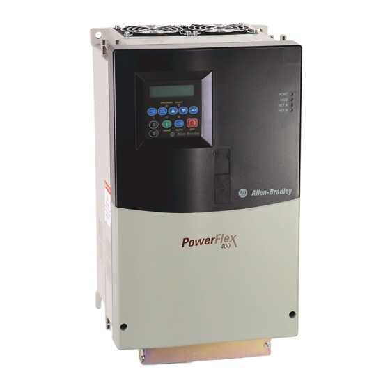
Allen-Bradley PowerFlex 400 Technical Data Manual
Adjustable frequency
ac drives for fan &
pump applications
Hide thumbs
Also See for PowerFlex 400:
- Installation instructions manual (218 pages) ,
- Quick start quide (29 pages) ,
- Product information (2 pages)
Table of Contents

Related Manuals for Allen-Bradley PowerFlex 400


Summary of Contents for Allen-Bradley PowerFlex 400
- Page 1 DATASHEET ALLEN BRADLEY 22-RFD050 OTHER SYMBOLS: 22RFD050, 22 RFD050, 22-RFD050 RGB ELEKTRONIKA AGACIAK CIACIEK SPÓŁKA JAWNA Jana Dlugosza 2-6 Street 51-162 Wrocław www.rgbelektronika.pl Poland [email protected] +48 71 325 15 05 www.rgbautomatyka.pl www.rgbautomatyka.pl www.rgbelektronika.pl...
- Page 2 YOUR PARTNER IN MAINTENANCE Repair this product with RGB ELEKTRONIKA ORDER A DIAGNOSIS LINEAR ENCODERS SYSTEMS INDUSTRIAL COMPUTERS ENCODERS CONTROLS SERVO AMPLIFIERS MOTORS MACHINES OUR SERVICES POWER SUPPLIERS OPERATOR SERVO PANELS DRIVERS At our premises in Wrocław, we have a fully equipped servicing facility. Here we perform all the repair works and test each later sold unit.
- Page 3 Technical Data PowerFlex ® Adjustable Frequency AC Drives for Fan & Pump Applications...
-
Page 4: Table Of Contents
Catalog Number Explanation ......8 PowerFlex 400 Standard Drives ......9 User Installed Options . -
Page 5: Product Overview
Product Overview Packaging • IP20, NEMA/UL Type 1 - For conventional mounting inside or outside a control cabinet in a 45°C (113°F) ambient. • Flange Type - Frame C ratings through 15 kW (20 HP) @ 380- 480V AC and 7.5 kW (10 HP) @ 200-240V AC allow for mounting heatsink through back of an enclosure, thus removing a large portion of the heat inside a cabinet. -
Page 6: Communications
Product Overview Communications • Supports Drive Serial Interface (DSI) communication modules (DeviceNet™, EtherNet/IP™, PROFIBUS™ DP, LonWorks®, BACnet®) and accessories. • Embedded Modbus RTU, P1-FLN and Metasys N2 protocols are parameter selectable and require no additional hardware or software. • Integral RS485 communications can be used for programming from a PC. -
Page 7: Application Features
Purge The PowerFlex 400 drive has an input which can be wired to a fire control panel or other fire/life safety systems allowing control of the drive to be overridden. A purge input will start the drive at a programmable purge speed regardless of the selected start source. -
Page 8: Proportional, Integral, Differential Control Loop
Proportional, Integral, Differential Control Loop The PowerFlex 400 has a built-in PID (Proportional, Integral, Differential) control loop. The PID loop is used to maintain a process variable, such as pressure or flow, at a desired set point. The PID loop works by subtracting the PID feedback from a reference and generating an error value. -
Page 9: Product Selection Guide
AC line. During an AutoSwap, the motor directly connected to the PowerFlex 400 drive is stopped and the contactor is opened. The contactor of the next motor that will be controlled by the PowerFlex 400 drive is opened if running across the AC line. -
Page 10: Catalog Number Explanation
Position Number – Enclosure Drive Rating Code Enclosure Code Type 200…240V Input Panel Mount - IP20, PowerFlex 400 Code Amps kW (Hp) Frame NEMA/UL Type Open 2.2 (3.0) Panel Mount - IP30, 17.5 3.7 (5.0) NEMA/UL Type 1 5.5 (7.5) -
Page 11: Powerflex 400 Standard Drives
Drive terminals are sized according to UL. Depending on operating ambient and wire used, some local or national codes may require a larger wire size than what the power terminals can accept. Multiple conductors, 90°C wire, and/or lugs may be required. Refer to the PowerFlex 400 User Manual for details on terminal block wire ranges. -
Page 12: User Installed Options
Description: LCD Display, Remote Panel Mount, Digital Speed Control, CopyCat capable, IP66, NEMA/UL Type 4X/12) indoor use only, Includes 2.0 meter cable. Note: Remote HIM display and keypad are different than PowerFlex 400 integral keypad. See the PowerFlex 400 User Manual for details. - Page 13 22C-CCC Description: Houses the Communication Adapter for Frame C drives. Note: This cover adds 25 mm (0.98 in.) to the overall depth of the drive and is only required for Frame C PowerFlex 400 drives. Serial Flash Firmware Kit AK-U9-FLSH1 Description: Use a PC to update drive firmware.
-
Page 14: Installation Considerations
Installation Considerations Input and Output Line Reactors (Loose) 208V, 60 Hz, Three-Phase PowerFlex 400 Ratings Catalog Number Amps IP00 (NEMA/UL Type Open) IP11 (NEMA/UL Type 1) 3% Impedance 1321-3R12-A 1321-3RA12-A 1321-3R18-A 1321-3RA18-A 1321-3R25-A 1321-3RA25-A 1321-3R35-A 1321-3RA35-A 1321-3R45-A 1321-3RA45-A 1321-3R55-A 1321-3RA55-A 18.5... -
Page 15: Installation Considerations
Installation Considerations Input and Output Line Reactors (Loose) 480V, 60 Hz, Three-Phase PowerFlex 400 Ratings Catalog Number Amps IP00 (NEMA/UL Type Open) IP11 (NEMA/UL Type 1) 3% Impedance 1321-3R8-C 1321-3RA8-C 1321-3R12-B 1321-3RA12-B 1321-3R12-B 1321-3RA12-B 1321-3R18-B 1321-3RA18-B 1321-3R25-B 1321-3RA25-B 1321-3R35-B 1321-3RA35-B 18.5... -
Page 16: Installation Considerations
Installation Considerations EMC Filters (Loose) 200-240V, 50/60 Hz, Three-Phase PowerFlex 400 Ratings Catalog Number Amps 22-RF034-CS 17.5 22-RF034-CS 22-RF034-CS 22-RF034-CS 22-RFD070 22-RFD100 18.5 22-RFD100 22-RFD150 22-RFD150 22-RFD180 380-480V, 50/60 Hz, Three-Phase Catalog Number PowerFlex 400 Ratings Amps 22-RF018-CS 10.5 22-RF018-CS... -
Page 17: Installation Considerations
1321-3TW040-BA 1321-3TW040-CA 1321-3TW051-AA 1321-3TW051-BA 1321-3TW051-CA 1321-3TH063-AA 1321-3TH063-BA – 460V AC, 3 Phase, 60 Hz Secondary PowerFlex 400 Drive Ratings IP32 (NEMA/UL Type 3R) Isolation Transformer Catalog Number Amps 230 Volt Primary 460 Volt Primary 575 Volt Primary 1321-3TW005-AB 1321-3TW005-BB 1321-3TW005-CB... -
Page 18: Power Wiring
Installation Considerations Power Wiring PowerFlex 400 drives have the following built in protective features to help simplify installation. • Ground fault protection while starting and running ensures reliable operation • Electronic motor overload protection increases motor life • 6kV transient protection provides increased robustness for 380-480V system voltages There are many other factors that must be considered for optimal performance in any given application. -
Page 19: Power Terminal Block
Installation Considerations Power Terminal Block Terminal Block Specifications Name Frame Description Wire Size Range Recommended Torque Maximum Minimum Power Terminal Block All power terminals 8.4 mm (8 AWG) 1.3 mm (16 AWG) 3.7 N-m (33 lb.-in.) All power terminals 33.6 mm (2 AWG) 8.4 mm (8 AWG) -
Page 20: Control Wiring
Installation Considerations Control Wiring • The control logic is 24V DC and can be set for either Sink or Source control via a DIP switch setting. • Control terminal screws are sized for a conventional blade screw driver. • I/O Terminals 1, 2 and 3 are semi-programmable and dedicated for Stop, Start, Reverse, and SW Enable inputs. These I/O Terminals can be programmed for 2- or 3-Wire operation to meet application requirements. - Page 21 RS485 (DSI) Shield – Terminal connected to Safety Ground - PE when using the RS485 (DSI) Communication Port. Refer to the PowerFlex 400 User Manual, publication 22C-UM001…, for Important information regarding Stop commands and the [Digital Inx Sel] Purge option. Signal...
-
Page 22: Specifications
Specifications User Installed Relay Board Terminal Designations Signal Default Description Param. #3 Relay N.O. Ready/Fault Normally open contact for Number 3 Output Relay R221 #3 Relay Common – Common for Number 3 Output Relay #4 Relay N.O. Ready/Fault Normally open contact for Number 4 Output Relay R224 #4 Relay Common –... -
Page 23: Drive Specifications
Specifications Drive Specifications Drive Ratings Catalog Number Output Ratings Input Ratings Branch Circuit Protection Power Dissipation kW (HP) Amps Voltage Amps Fuses 140M Motor Contactors Min. Enclosure IP20 Open Range Protectors Volume (in. Watts 45°C 50°C 200 - 240V AC – 3-Phase Input, 0 - 230V 3-Phase Output 22C-B012N103 2.2 (3.0) 180-265... - Page 24 Specifications Category Specification Agency Listed to UL508C and CAN/CSA-22.2 Certification Listed to UL508C for plenums ® Certified to AS/NZS, 1997 Group 1, Class A Marked for all applicable European Directives EMC Directive (89/336) EN 61800-3, EN 50081-1, EN 50082-2 Low Voltage Directive (73/23/EEC) EN 50178, EN 60204 The drive is also designed to meet the appropriate portions of the following specifications: NFPA 70 - US National Electrical Code...
- Page 25 Specifications Category Specification Control Inputs Digital: Quantity: (3) Semi-programmable (4) Programmable Type Source Mode (SRC): 18-24V = ON, 0-6V = OFF Sink Mode (SNK): 0-6V = ON, 18-24V = OFF Analog: Quantity: (1) Isolated, –10 to 10V or 4-20mA (1) Non-isolated, 0 to 10V or 4-20mA Specification Resolution: 10-bit...
-
Page 26: Parameter List
Specifications Parameter List Parameter Parameter Name Description Factory Default Number Basic Display Group b001 Output Freq Output frequency present at T1, T2 & T3 (U, V & W) Read Only b002 Commanded Freq Value of the active frequency command Read Only b003 Output Current Output current present at T1, T2 &... - Page 27 Specifications Parameter Parameter Name Description Factory Default Number T073 Analog In 2 Sel 8 settings; Current Mode (0-20 mA), Current Mode (4-20 mA), Voltage Mode - Unipolar (0-10V), Voltage Mode - Unipolar Voltage Mode - Bipolar (-10 to +10V), Current Mode Square Root (0-20 mA), Current Mode (0-10V) Square Root (4-20 mA), Voltage Mode Square Root - Unipolar (0-10V), Voltage Mode Square Root - Bipolar (-10 to +10V)
- Page 28 Specifications Parameter Parameter Name Description Factory Default Number A158 PID Deadband 0.0 to 10.0% 0.0% A159 PID Preload 0.0 to 320.0 Hz 0.0 Hz A160 Process Factor 0.1 to 999.9 30.0 A163 Auto Rstrt Tries 0 to 9 A164 Auto Rstrt Delay 0.0 to 160.0 Secs 1.0 Secs A165...
- Page 29 Specifications Parameter Parameter Name Description Factory Default Number R242 Aux 1 Stop Freq 0.0 to 320.0 Hz 25.0 Hz R245 Aux 2 Stop Freq R248 Aux 3 Stop Freq R243 Aux 1 Ref Add 0.0 to 100.0% 0.0% R246 Aux 2 Ref Add R249 Aux 3 Ref Add R250...
-
Page 30: Approximate Dimensions
Specifications Approximate Dimensions Ratings are in kW and (HP). Frame 240V AC – 3-Phase 480V AC – 3-Phase 2.2 (3.0) 5.5 (7.5) 2.2 (3.0) 7.5 (10) 3.7 (5.0) 7.5 (10) 4.0 (5.0) 11 (15) 5.5 (7.5) 15 (20) 11 (15) 18.5 (25) 18.5 (25.0) 30 (40) - Page 31 Specifications 370.0 (14.57) 259.2 (10.21) ∅ 8.5 (0.33) 335.0 (13.19) 315.2 (12.41) 240.2 (9.46) 130.2 (5.13) ∅ 28.5 55.2 (2.17) (1.12) ∅ 22.2 (0.87) 605.5 234.9 (23.84) (9.25) 204.9 567.4 (8.07) (22.34) 174.9 (6.89) Frame E 425.0 (16.73) 264.0 (10.39) ∅...
- Page 32 Specifications 425.0 (16.73) 381.0 (15.00) 264.0 (10.39) 367.5 (14.47) 302.5 (11.91) 92.0 122.5 (4.82) (3.62) 21.5 57.5 (2.26) (0.85) 892.0 (35.12) 244.6 819.5 (9.62) (32.26) 199.6 (7.85) Frame G 358.6 (14.12) 529.2 (20.83) 480.0 (18.90) 489.6 (19.28) 413.7 (16.29) 117.5 (4.63) 115.5 (4.55) 22.3...
- Page 33 Specifications Flange Mount Drive 130.3 (5.13) 105.8 138.2 (11.81) (4.17) (5.44) (6.46) (0.21) (0.31) 307.5 (12.11) 230.6 (9.08) 291.5 (11.48) (12.8) 153.8 (6.06) 76.9 (3.03) 22B-CCC (3.54) (0.31) (7.09) Frame C — Flange Mount EMC Line Filters Dimensions are in millimeters and (inches) Catalog Numbers: 22-RF018-CS, 22-RF026-CS, 22-RF034-CS (2.36) (5.12)
- Page 34 Specifications Catalog Numbers: 22-RFD036, 22-RFD050, 22-RFD070, 22-RFD100, 22-RFD150, 22-RFD180 Catalog Number 22-RFD036 74 (2.91) 272 (10.71) 161 (6.34) 60 (2.36) 258 (10.16) 7.5 (0.30) 7 (0.28) 22-RFD050 93 (3.66) 312 (12.28) 190 (7.48) 79 (3.11) 298 (11.73) 13.5 (0.53) 7 (0.28) 22-RFD070 93 (3.66) 312 (12.28)
- Page 35 Specifications Catalog Numbers: 22-RFD323 and 22-RFD480 (0.24) ø 9 (0.35) 12.5 45° (0.49) (0.39) (1.97) (2.36) (2.36) (0.12) (2.52) Ø 10.8 (0.71) (0.43) (11.81) (0.98) Catalog Number 22-RFD323 300 (11.81) 735 (28.94) 145 (5.71) 275 (10.83) 689 (27.13) 64 (2.52) 180 (7.09) 22-RFD480 300 (11.81)
- Page 36 Specifications Human Interface Module (HIM) Dimensions NEMA/UL Type 4X/12 Remote (Panel Mount) Small HIM NEMA/UL Type 1 Bezel – Dimensions are in millimeters and (inches) Catalog Number: 22-HIM-B1 – Dimensions are in millimeters and (inches) Catalog Number: 22-HIM-C2S 11.1 25,0 93,0 (0.44) (0.98)
-
Page 37: Description
Configured Drives Programs Description The Configured Drives program allows users to create Disconnect and Contactor Bypass packages based on their specific needs and requirements. A limited factory installed option set is offered to optimize package configurations while providing a versatile and cost- effective solution. -
Page 38: Product Selection Guide
Catalog Number Explanation Position 23C – Drive Enclosure Code Rating Code Type Code Enclosure Reserved PowerFlex 400 NEMA/UL Type 1 NEMA/UL Type 12 with Fan and Filter Package NEMA/UL Type 3R ‡ Voltage Rating Code Description NEMA/UL Type 4 ‡ Code Voltage Main Input Disconnect ‡... -
Page 39: Powerflex 400 Nema/Ul Type 1 Enclosure (Position D = A)
Product Selection Guide PowerFlex 400 NEMA/UL Type 1 Enclosure (Position d = A) 208V ac, Main Input Disconnect Drive Ratings Fused Disconnect (Position j = A) Output Current Frame Amps (40°C) Size Catalog Number 23C-X012A103NNAANN 16.8 23C-X017A103NNAANN 23C-X024A103NNAANN 30.8 23C-X033A103NNAANN 46.2... - Page 40 Product Selection Guide 460V ac, 3 Contactor Full Feature Bypass with Disconnect/Circuit Breaker Drive Ratings Fused Disconnect (Position j = B) Circuit Breaker (Position j = N) Output Current Frame Amps (40°C) Size Catalog Number Catalog Number 23C-D6P0A103NNBANN – 23C-D010A103NNBANN –...
- Page 41 Product Selection Guide PowerFlex 400 NEMA/UL Type 12 Enclosure (Position d = H) 208V ac, Main Input Disconnect/Circuit Breaker Drive Ratings Fused Disconnect (Position j = A) Circuit Breaker (Position j = M) Output Current Frame Amps (40°C) Size Catalog Number...
- Page 42 23C-D142H103NNBANN 23C-D142H103NNNANN 23C-D170H103NNBANN 23C-D170H103NNNANN 23C-D208H103NNBANN 23C-D208H103NNNANN PowerFlex 400 NEMA/UL Type 3R Enclosure (Position d = X) 208V ac, Main Input Disconnect/Circuit Breaker Drive Ratings Fused Disconnect (Position j = A) Circuit Breaker (Position j = M) Output Current Frame Amps (40°C)
- Page 43 460V ac, Main Input Disconnect/Circuit Breaker Drive Ratings Fused Disconnect (Position j = A) Circuit Breaker (Position j = M) Output Current Frame Amps (40°C) Size Catalog Number Catalog Number 23C-D6P0X103NNAANN 23C-D6P0X103NNMANN 23C-D010X103NNAANN 23C-D010X103NNMANN 23C-D012X103NNAANN 23C-D012X103NNMANN 23C-D017X103NNAANN 23C-D017X103NNMANN 23C-D022X103NNAANN 23C-D022X103NNMANN 23C-D030X103NNAANN 23C-D030X103NNMANN 18.5...
- Page 44 PowerFlex 400 NEMA/UL Type 4 Enclosure (Position d = E) 208V ac, Main Input Disconnect/Circuit Breaker Drive Ratings Fused Disconnect (Position j = A) Circuit Breaker (Position j = M) Output Current Frame Amps (40°C) Size Catalog Number Catalog Number...
-
Page 45: Factory Installed Options
460V ac, 3 Contactor Full Feature Bypass with Disconnect/Circuit Breaker Drive Ratings Fused Disconnect (Position j = B) Circuit Breaker (Position j = N) Output Current Frame Amps (40°C) Size Catalog Number Catalog Number 23C-D6P0E103NNBANN 23C-D6P0E103NNNANN 23C-D010E103NNBANN 23C-D010E103NNNANN 23C-D012E103NNBANN 23C-D012E103NNNANN 23C-D017E103NNBANN 23C-D017E103NNNANN 23C-D022E103NNBANN... - Page 46 www.rockwellautomation.com Power, Control and Information Solutions Headquarters Americas: Rockwell Automation, 1201 South Second Street, Milwaukee, WI 53204 USA, Tel: (1) 414.382.2000, Fax: (1) 414.382.4444 Europe/Middle East/Africa: Rockwell Automation, Vorstlaan/Boulevard du Souverain 36, 1170 Brussels, Belgium, Tel: (32) 2 663 0600, Fax: (32) 2 663 0640 Asia Pacific: Rockwell Automation, Level 14, Core F, Cyberport 3, 100 Cyberport Road, Hong Kong, Tel: (852) 2887 4788, Fax: (852) 2508 1846 Publication 22C-TD001D-EN-P —...