ABB ACH550 series User Manual
E-clipse bypass configurations (bcr, bdr, vcr, or vdr) for drives (1...400 hp)
Hide thumbs
Also See for ACH550 series:
- User manual (58 pages) ,
- Installation manual (42 pages) ,
- Installation, operation and maintenance manual (18 pages)

Related Manuals for ABB ACH550 series


Summary of Contents for ABB ACH550 series
- Page 1 User’s Manual E-Clipse Bypass Configurations (BCR, BDR, VCR, or VDR) for ACH550 Drives (1…400 HP)
- Page 2 • Technical Data E-Clipse Bypass Configurations (BCR, BDR, VCR or VDR) for ACH550 Drives (1…400 HP) • Safety • Installation • Start-Up • Embedded Fieldbus • Fieldbus Adapter • Diagnostics • Maintenance • Technical Data © 2009 ABB Inc. All Rights Reserved.
- Page 3 Bypass is connected to the line. Disconnect and lock out power to the drive before servicing the drive. Failure to disconnect power may cause serious injury or death. Note! For more technical information, contact the factory or your local ABB sales representative. Safety...
-
Page 4: Use Of Warnings And Notes
E-Clipse Bypass Configurations for ACH550 Drives Use of Warnings and Notes There are two types of safety instructions throughout this manual: • Notes draw attention to a particular condition or fact, or give information on a subject. • Warnings caution you about conditions which can result in serious injury or death and/or damage to the equipment. -
Page 5: Table Of Contents
E-Clipse Bypass Configurations for ACH550 Drives Table of Contents Safety Use of Warnings and Notes ........1 Table of Contents Installation Application . -
Page 6: Table Of Contents
E-Clipse Bypass Configurations for ACH550 Drives Technical Data (Continued) E-Clipse Bypass Control Unit Connections . . 96 (Supplement to ACH550-UH User’s Manual) Dimensions and Weights (Supplement to ACH550-UH User’s Manual) ..97 Applicable Standards ......... . . 103 Table of Contents... -
Page 7: Application
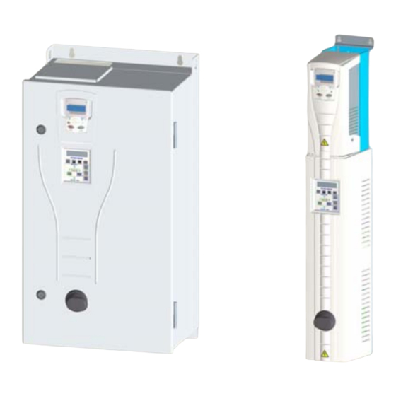
E-Clipse Bypass Configurations for ACH550 Drives Installation Study these installation instructions carefully before proceeding. Failure to observe the warnings and instructions may cause a malfunction or personal hazard. WARNING! Before you begin read "Safety" on page 1. WARNING! When the ACH550 with E-Clipse Bypass is connected to the line power, the Motor Terminals T1, T2, and T3 are live even if the motor is not running. - Page 8 E-Clipse Bypass Configurations for ACH550 Drives The following shows the front view of the ACH550 E-Clipse Bypass vertical configuration, and identifies the major components. ACH550 Drive ACH-CP-B Control Panel E-Clipse Bypass Control Panel Operating Handle for Disconnect Switch or Circuit Breaker E-Clipse Bypass BP0091 The following shows the front view of the ACH550 E-Clipse Bypass standard...
-
Page 9: Installation Flow Chart
E-Clipse Bypass Configurations for ACH550 Drives The following is a typical power diagram. Drive with E-Clipse Bypass Disconnect Switch Drive Output Bypass or Circuit Breaker Contactor Control 3 Phase ACH550 Motor Input Power Drive Service Switch Bypass (Optional) Contactor Drive Input Fuse Installation Flow Chart The installation of E-Clipse Bypass Configurations for ACH550 drives follows the outline below. -
Page 10: Preparing For Installation (Supplement To Ach550-Uh User's Manual)
S/N 2090501769 • Type code label attached on the heat sink – on the right side of the unit cover. ABB Inc. Input 3PH 48...63 Hz Output 3PH 0...500 Hz Made in the USA of foreign parts... -
Page 11: Installing The Wiring (Supplement To Ach550-Uh User's Manual)
E-Clipse Bypass Configurations for ACH550 Drives Ratings and Frame Size The chart in the “Ratings” section of the ACH550-UH User’s Manual lists technical specifications, and identifies the drive’s frame size – significant, since some instructions in this document vary, depending on the drive’s frame size. To read the Ratings table, you need the “Output current rating”... - Page 12 E-Clipse Bypass Configurations for ACH550 Drives Wiring Overview (Supplement to ACH550-UH User’s Manual) Connection Diagrams – Vertical E-Clipse Bypass ACH550 Vertical E-Clipse Bypass units are configured for wiring access from the bottom only. The following figure shows the Vertical E-Clipse Bypass wiring connection points.
- Page 13 E-Clipse Bypass Configurations for ACH550 Drives Connection Diagrams – Standard E-Clipse Bypass (Wall Mounted) ACH550 Standard E-Clipse Bypass units are configured for wiring access from the top. The following figure shows the Standard E-Clipse Bypass (wall mounted) wiring connection points. Refer to the ACH550-UH User's Manual for control connections to the drive.
- Page 14 E-Clipse Bypass Configurations for ACH550 Drives User Power Cable Guides ACH550 Drive E-Clipse Bypass Control Board Terminals (X2) Disconnect Switch or Circuit Breaker Input Ground Lug Input Power Terminals Motor Terminals Output Ground Lug Service Switch (optional) ACH550 Drive Output Ground Lug Input Ground Lug Motor Terminals Input Power Terminals...
- Page 15 E-Clipse Bypass Configurations for ACH550 Drives Connection Diagrams – Standard E-Clipse Bypass (R8, Floor Mounted) ACH550 Standard E-Clipse Bypass units are configured for wiring access from the top. The following figure shows the Standard E-Clipse Bypass (floor mounted) wiring connection points. Refer to the ACH550-UH User's Manual for control connections to the drive.
- Page 16 E-Clipse Bypass Configurations for ACH550 Drives Install the Line Input Wiring (Supplement to ACH550-UH User’s Manual) Line Input Connections – Vertical E-Clipse Bypass Configurations Connect the input power to the terminals at the bottom of the disconnect switch or circuit breaker as shown below.
- Page 17 E-Clipse Bypass Configurations for ACH550 Drives UL Type 3R Configuration (B1/B2) Input Power Cables WARNING! Check the motor and motor wiring insulation before connecting the ACH550 to line power. Follow the procedure in the ACH550-UH User’s Manual. Before proceeding with the insulation resistance measurements, check that the ACH550 is disconnected from incoming line power.
- Page 18 E-Clipse Bypass Configurations for ACH550 Drives User Power Cable Guides Motor Cables Standard Configuration (B3) Standard Configuration (B1/B2) Motor Cables Ground UL Type 3R Configuration (B1/B2) Installation...
- Page 19 E-Clipse Bypass Configurations for ACH550 Drives Install the Control Wiring (Supplement to ACH550-UH User’s Manual) Connect control wiring to terminal block X1 on the ACH550 control board and to terminal block X2 on the E-Clipse Bypass control board. For more information on these connections, refer to the following: •...
- Page 20 E-Clipse Bypass Configurations for ACH550 Drives Basic Control Connections for E-Clipse HVAC Default E-Clipse HVAC Default Parameters Changed Relative to E-Clipse HVAC Default Parameter Number Description Setting Smoke Control (Override1) is a fixed input. Closing Digital Input 6 will place the E-Clipse Bypass in Smoke Control mode which may reassign the function of the other Digital Inputs.
- Page 21 E-Clipse Bypass Configurations for ACH550 Drives Initial Settings and Checks Control Panel Settings and Checks Apply power to the E-Clipse Bypass unit. The ACH550 Control Panel should show the operating status of the drive. If the E-Clipse Bypass Control Panel displays a PHASE SEQ (Phase Sequence) fault, remove power, wait at least 5 minutes and then swap any two input phase wires.
- Page 22 E-Clipse Bypass Configurations for ACH550 Drives • Parameter 1608 must be set to “Comm” • Parameter 5303 must be set to “76.8 kb/s” • Parameter 5305 must be set to “DCU PROFILE” • Parameter 5304 must be set to “8 EVEN 1” •...
- Page 23 E-Clipse Bypass Configurations for ACH550 Drives that closed contacts or jumpers connect terminal X2:3 to X2:4 and X2:2 to X2:7 on the bypass control board. 4. The Drive Selected LED should be illuminated. If not, press the Drive Select key to switch to Drive mode.
- Page 24 E-Clipse Bypass Configurations for ACH550 Drives Note! The settings for ALL external serial communication between the ACH550 with E-Clipse Bypass and any Building Automation System are configured using the E- Clipse Bypass operator panel. DO NOT attempt to configure the external serial communication connection using the ACH550 operator panel! The settings for internal communication between the ACH550 and the E-Clipse Bypass are configured at the factory and require no adjustment.
- Page 25 E-Clipse Bypass Configurations for ACH550 Drives 4. The ACH550 Control Panel display should be illuminated. On the E-Clipse Bypass control panel, both the display and Enabled LED should be illuminated. If the Enabled LED is not illuminated solid green, check to see that closed contacts or jumpers connect terminal X2:3 to X2:4 and X2:2 to X2:7 on the bypass control board.
- Page 26 E-Clipse Bypass Configurations for ACH550 Drives 13. Press the DOWN arrow on the drive control panel until the speed and frequency indications return to “0.0.” 14. Press the OFF key on the drive control panel. Note that the bottom line of the drive contol panel display indicates “Off.”...
-
Page 27: Check E-Clipse Bypass Jumpers And Switches
On some ACH550 E-Clipse Bypasses, the circuit breaker has adjustable settings for instantaneous current protection. The factory default settings are practical for most applications. Refer to the “ABB SACE Instruction Sheet” (supplied with these units) for additional information on the adjustment of these settings. -
Page 28: E-Clipse Bypass Application Macros
E-Clipse Bypass Configurations for ACH550 Drives E-Clipse Bypass Application Macros The following figures show a variety of configurations and connections using the available E-Clipse Bypass Macros. E-Clipse Bypass macros are selected and configured using the E-Clipse Bypass Control Panel. E-Clipse Bypass macros provide a simple, easy method of configuring the E-Clipse Bypass unit to the most commonly used HVAC applications. - Page 29 E-Clipse Bypass Configurations for ACH550 Drives E-Clipse HVAC Default Parameters Changed Relative to E-Clipse HVAC Default Parameter Number Description Setting Smoke Control (Override1) is a fixed input. Closing Digital Input 6 will place the E-Clipse Bypass in Smoke Control mode which may reassign the function of the other Digital Inputs. Refer to the Smoke Control (Override1) documentation.
- Page 30 E-Clipse Bypass Configurations for ACH550 Drives Damper Parameters Changed Relative to HVAC Default Parameter Number Description Setting 1602 Damper End Switch RUN ENABLE (Run Permissive) 1604 Firestat, Freezestat, High Static Switch START EN 2 (Saftey Interlock 2) Smoke Control (Override1) is a fixed input. Closing Digital Input 6 will place the E-Clipse Bypass in Smoke Control mode which may reassign the function of the other Digital Inputs.
- Page 31 E-Clipse Bypass Configurations for ACH550 Drives Retrofit Parameters Changed Relative to HVAC Default Parameter Number Description Setting 1602 Damper End Switch RUN ENABLE (Run Permissive) 1701 Refer to page 36 OVERRIDE 2 (Bypass Override) Smoke Control (Override1) is a fixed input. Closing Digital Input 6 will place the E-Clipse Bypass in Smoke Control mode which may reassign the function of the other Digital Inputs.Refer to the Smoke Control (Override1) documentation.
- Page 32 E-Clipse Bypass Configurations for ACH550 Drives Smoke Control (Override1) Parameter Number Description Setting 1602 Damper End Switch RUN ENABLE (Run Permissive) 1603 High Pressure Switch, High Priority Safties START EN 1 (Safety Interlock 1) 1604 Supply Smoke Detector, Emergency Shutdown START EN 2 (Saftey Interlock 2) 1605 Freezestat, Low Priority Safties...
- Page 33 E-Clipse Bypass Configurations for ACH550 Drives Typical Wiring Diagrams Showing a Conventional Starter Wiring and Use of the E-Clipse Bypass Typical system wiring with use of E-Clipse Bypass: X2 E-Clipse Bypass Controller Input Normal Operation: • Close Start/Stop (X2:5) • Fan starts, assuming that X2: 6, 7, 8, and 9 (DI1) Start/Stop...
- Page 34 E-Clipse Bypass Configurations for ACH550 Drives Alternate Wiring Options Parameters Changed Relative to E-Clipse HVAC Default Parameter Number Description Setting * Smoke Control (Override1) is a fixed input. Closing Digital Input 6 will place the E-Clipse Bypass in Smoke Control mode which may reassign the function of the other Digital Inputs.Refer to the Smoke Control (Override1) documentation.
-
Page 35: Bypass Control Panel
E-Clipse Bypass Configurations for ACH550 Drives Overview of Bypass Functionality Bypass Control Panel The figure below shows the bypass control panel and identifies the keys and LED indicating lights. The functions of the various keys and LEDs are described in the following paragraphs. - Page 36 E-Clipse Bypass Configurations for ACH550 Drives Bypass Faulted LED The Bypass Faulted LED is illuminated or flashes red when the motor or bypass protection functions have shut down the bypass. The specific nature of the fault is indicated on the bypass control display. Refer to the Diagnostics and Troubleshooting section of this manual for more details.
-
Page 37: Operating Modes
E-Clipse Bypass Configurations for ACH550 Drives Off/Reset Key The Off/Reset Key may be used to manually stop the motor if the motor has been running on bypass power. The Off/Reset key also resets most bypass faults. It may take several minutes before the bypass can be reset after an overload trip. If a bypass fault condition is present the second press of this key places the bypass in the OFF mode. - Page 38 E-Clipse Bypass Configurations for ACH550 Drives in Smoke Control mode, the system does not respond to some inputs and does respond to other inputs. The system will ignore low priority safeties such as FreezeStats and return duct smoke detectors. While in Smoke Control mode, the system will respond to high priority safeties such as high static pressure and damper end-switch proofs.
- Page 39 E-Clipse Bypass Configurations for ACH550 Drives Bypass Override input contact is closed, the system is forced to bypass and does not respond to the Drive and Bypass keys. The Motor Run LED flashes green when the system is in override. While in Bypass Override the system responds to bypass overloads and programmed faults.
- Page 40 E-Clipse Bypass Configurations for ACH550 Drives Hand or Auto mode, the motor will start across the line as soon as power is applied. If the system is in the Drive mode with the drive in the Auto mode, the motor will start on the drive as soon as power is applied.
- Page 41 E-Clipse Bypass Configurations for ACH550 Drives Start command is present, the Enabled LED will flash green and the motor is prevented from running. Safety Interlock (DI2…DI5) The Safety Interlock input(s) are connected to the series combination of any external normally closed interlock contacts, such as Firestat, Freezestat, and high static pressure switches –...
- Page 42 E-Clipse Bypass Configurations for ACH550 Drives • There can be no fault present in the system. The Start command can come from the bypass control board terminal block, the drive control panel, the bypass control panel, or serial communications, depending on the operational mode selected.
- Page 43 E-Clipse Bypass Configurations for ACH550 Drives Drive Alarm (11) [DRIVE ALARM] If configured for Drive Alarm, the relay is energized when a drive alarm is present. The specific nature of the alarm is indicated on the drive control panel display. The Drive Alarm relay is de-energized during normal operation.
- Page 44 E-Clipse Bypass Configurations for ACH550 Drives Bypass Underload (20) [BYP UNDERLD] If configured for Bypass Underload, the relay is energized when the bypass motor underload level has fallen below the programmed protection setting. This output is often used for broken belt indication. The Bypass Underload relay is de-energized during normal operation.
- Page 45 E-Clipse Bypass Configurations for ACH550 Drives Energy Savings Estimator The ABB E-Clipse Bypass is capable of displaying the estimated energy savings provided by variable frequency drive operation. Additional displays provide estimated dollar savings based upon a user provided cost per kilowatt hour and estimated CO avoidance in tons.
- Page 46 E-Clipse Bypass Configurations for ACH550 Drives Note! The learn mode is terminated by any of the following conditions: User clears the learn mode request (Parameter 1628 = NOT SEL) The running time in learn mode equals the time set by Parameter 1629 ...
-
Page 47: Hvac Bypass Control Panel Operation
E-Clipse Bypass Configurations for ACH550 Drives Start-up HVAC Bypass Control Panel Operation LCD Display Down Escape Enter Enabled LED ON/Hand Key Drive and Bypass Selected/Faulted LEDs OFF/Reset Key Auto Key Drive/Bypass Select Keys Motor Run LED Start-Up can be performed in two ways: •... -
Page 48: Start-Up By Changing The Parameters Individually From The Parameter List
E-Clipse Bypass Configurations for ACH550 Drives Select the appropriate Parameter with * 1 6 0 1 S T A R T / S T O P the Up/Down arrows and press ENTER ENTER 1 6 1 3 B P D I S A B L E Press the Up/Down arrows to change the Parameter Value. -
Page 49: Modes
E-Clipse Bypass Configurations for ACH550 Drives Note! In the Parameter Edit mode the current parameter value appears below the parameter name. Note! To view the default parameter value, press the Up/Down arrows simultaneously. Press Enter to restore the default parameter value or press ESC to leave the Parameter Edit mode. - Page 50 E-Clipse Bypass Configurations for ACH550 Drives BOOT Default Display Main Menu Bypass Status Enter System Selected Enter Status 1 Bypass Status Bypass Mode Status 2 Any state Parameters Fault Start-up Enter Enter 9802 Parameter edit Reset Parameter Menu 9902 Bypass Fault (Flashes over Blank Display )
- Page 51 E-Clipse Bypass Configurations for ACH550 Drives Parameter Descriptions Parameter Settings Macro Used HVAC Default Damper Retrofit Smoke Control Parameters Changed Relative to Macro Default Parameter/Code Custom Value/Setting Comments Parameter Descriptions...
-
Page 52: Parameter Listing
E-Clipse Bypass Configurations for ACH550 Drives Parameter Descriptions Parameter Listing Parameter data is specific to bypass firmware version . Group 01 Code Name Resolution Range Default Description 0101 MOTOR 0.1 A — Display motor current in any mode. CURR 0102 INPUT VOLT —... - Page 53 E-Clipse Bypass Configurations for ACH550 Drives Group 03 Code Name Resolution Range Default Description 0301 FBUS CW 1 — b0: 1 = Start Control word 1 from field bus b1: 1 = Fault reset b2: 1 = Run disable b3: 1 = Field bus local b4: 1 = Start disable 1 b5: 1 = Start disable 2 b6: 1 = Start disable 3...
- Page 54 E-Clipse Bypass Configurations for ACH550 Drives Group 03 Code Name Resolution Range Default Description Bypass fault status, word 2 0306 FLT WORD 2 — b0: 1 = Motor Underload b1: 1 = Max cycling fault b2: 1 = Drive link fault b3: 1 = Reverse rotation b4: 1 = Phase A current measurement...
- Page 55 E-Clipse Bypass Configurations for ACH550 Drives Group 03 Code Name Resolution Range Default Description Bypass alarm status, word 2 0309 ALR WORD 2 — b0: not used b1: not used b2: Override 1 b3: Override 2 b4: 1 = Start Enable 1 b5: 1 = Start Enable 2 b6: 1 = Start Enable 3 b7: 1 = Start Enable 4...
- Page 56 E-Clipse Bypass Configurations for ACH550 Drives Group 04 Code Name Resolution Range Default Description 0409 F1 E2 TIME 2, before 00:00:00 - 23:59:58 Time before last fault of 2nd last event: hr:min:sec if time < 1 day 1, days 0 - 9999 days if time >= 1 day before 0410...
- Page 57 E-Clipse Bypass Configurations for ACH550 Drives Group 05 Code Name Resolution Range Default Description Status at last event 0501 LAST EVENT — b0: 1 = Bypass mode b1: 1 = Safeties In b2: 1 = Run Enable b3: 1 = Start b4: 1 = In Auto Transfer b5: 1 = Bypass Override b6: 1 = Fireman's Override...
- Page 58 E-Clipse Bypass Configurations for ACH550 Drives Group 14 Code Name Resolution Range Default Description BYP NOT Selects function for digital output. 1401 RO1 SELECT 0 = NOT SEL 1 = SYS READY Define the event or condition that 2 = SYS RUNNING activates relay 1.
- Page 59 E-Clipse Bypass Configurations for ACH550 Drives Group 14 Code Name Resolution Range Default Description 1411 R4 ON DLY 0.1 sec 0-3600.0s Delay from active state to active output. 1412 R4 OFF DLY 0.1 sec 0-3600.0s Delay from inactive state to inactive output.
- Page 60 E-Clipse Bypass Configurations for ACH550 Drives Group 16 Code Name Resolution Range Default Description 1608 AUTO XFR 0 = NOT SEL NOT SEL Enabled allows auto transfer to 1 = ENABLE bypass on all drive faults except the conditional faults which require an additional enable.
- Page 61 E-Clipse Bypass Configurations for ACH550 Drives Group 16 Code Name Resolution Range Default Description 1619 PAR LOCK 0 = LOCKED OPEN When switched to "LOCKED" 1 = OPEN prevents parameter changes from panel. Does not affect to Field Bus writes, expect changing the lock value itself: correct password must always be set first, even in case of Field...
- Page 62 E-Clipse Bypass Configurations for ACH550 Drives Group 16 Code Name Resolution Range Default Description 1626 MODE LOCK 0 = NOT SEL NOT SEL When Mode Lock is AUTO 1 = AUTO MODE MODE, the control panel will not 2 = LOCAL MODE allow switching to Hand or Off.
- Page 63 E-Clipse Bypass Configurations for ACH550 Drives Group 30 Code Name Resolution Range Default Description 3001 UL ACTION 0 = NOT SEL NOT SEL Selects action to be taken if 1 = FAULT ( 0) underload occurs. 2 = WARNING 3002 UL TIME 1 sec 10 - 400 sec...
- Page 64 E-Clipse Bypass Configurations for ACH550 Drives Group 32 Code Name Resolution Range Default Description 3206 FBK LOSS 0 = BYP STOP Bypass contactor operation if 1 = BYP START START drive link fault, drive AI2 loss or excessive cycling. Group 33 Code Name Resolution...
- Page 65 0=8 NONE 1, Read-only copy from Group 53. 1=8 NONE 2, 2=8 EVEN 1, 3=8 ODD 1 5005 PROFILE 0=ABB DRV LIM, Read-only copy from Group 53. 1=DCU PROFILE, 2=ABB DRV FULL 5006 BP OK MSG 0 - 65535 5007...
- Page 66 38.4, 57.6, 76.8 5304 EFB PARITY 0=8 NONE 1, 1=8 NONE 2, 2=8 EVEN 1, 3=8 ODD 1 5305 PROFILE 0=ABB DRV LIM, — 1=DCU PROFILE, 2=ABB DRV FULL 5306 DV OK MSG 0 - 65535 5307 DV CRC ERR...
- Page 67 E-Clipse Bypass Configurations for ACH550 Drives Group 53 Code Name Resolution Range Default Description 5319 DV PAR 19 0x0000 - 0xFFFF 0x0000 5320 DV PAR 20 Group 54 Code Name Resolution Range Default Description 5401 DATA IN 1 0 = Not In Use —...
-
Page 68: Notes
Bypass Configuration manual. E-Clipse Bypass parameter groups 14, 16, 17, 50, 53 and 98 can be changed for more specific network configuration. For protocol specific details for the EFB: BACnet, FLN, Modbus-RTU, and N2 download the ACH550 E-Clipse Bypass EFB User’s Manual (3AUA0000031267 REVA) from www.abb.us/drives. Embedded Fieldbus and Fieldbus Adapters... -
Page 69: Efb Electrical Installation
E-Clipse Bypass Configurations for ACH550 Drives EFB Electrical Installation The figure below shows the locations of the SW1 DIP switch and X2 terminals 26..30 on the E-Clipse Bypass control board. The function and setting of this switch and wire terminal connection are explained in the following section. -
Page 70: Efb Basic Configuration
E-Clipse Bypass Configurations for ACH550 Drives • To reduce noise on the network, terminate the EIA 485 network using 120 O resistors at both ends of the network. Use the DIP switch to connect or disconnect the termination resistors. See following diagram and table. Preferred Wiring Diagram (See ACH550 E-Clipse Bypass EFB User’s Manual (3AUA0000031267 REVA) for Alternate Wiring: •... - Page 71 Description section, for a complete list of parameters. E-Clipse Bypass parameter groups 14, 16, 17, 50, 53 and 98 can be changed for more specific network configuration. Download E-Clipse Bypass Embedded Fieldbus User Manual from http://www.abb.us/drives STEP 1: Establishing bypass communication with building management system...
- Page 72 E-Clipse Bypass Configurations for ACH550 Drives STEP 3: Drive Reference and/or PID Setpoint via Serial Communication Controller Bypass DRIVE SYSTEM Description Paremeter DRV & BYPASS 1103 Selects the signal source for external reference REF1 SELECT REF1 = COMM – Defines the fieldbus as the reference source. DRIVE SEE ACH550-01/02 User Manual for additional information CONTROL...
-
Page 73: Diagnostic Displays
E-Clipse Bypass Configurations for ACH550 Drives Diagnostics and Troubleshooting WARNING! Do not attempt any measurement, parts replacement or other service procedure not described in this manual. Such action will void the warranty, may endanger correct operation, and increase downtime and expense. -
Page 74: Correcting Faults
E-Clipse Bypass Configurations for ACH550 Drives Correcting Faults The recommended corrective action for faults is: • Use the following “Fault Listing” table to find and address the root cause of the problem. • Reset the system. Diagnostics and Troubleshooting... -
Page 75: Fault Listing
E-Clipse Bypass Configurations for ACH550 Drives Fault Listing Fault Fault Name In Panel Fault Possible Cause Corrective Action Code 3001 COIL CURR FBK RBCU is sensing Defective component Change RBCU abnormal current on RBCU feedback when neither contactor should be energized 3002 BYP CNTACT STUCK... - Page 76 E-Clipse Bypass Configurations for ACH550 Drives Fault Fault Name In Panel Fault Possible Cause Corrective Action Code 3006 UNDERVOLTAGE Message only occurs if Loose J7 connector on Check that J7 drive is controlling the RBCU unit connector is firmly motor and the power to seated in RBCU Loose input wiring the bypass is removed...
- Page 77 E-Clipse Bypass Configurations for ACH550 Drives Fault Fault Name In Panel Fault Possible Cause Corrective Action Code 3013 DRIVE 1ST START Fault generated if Run bypass unit in drive attempting to close the mode before attempting bypass contactor with bypass mode out running the bypass in drive mode first.
- Page 78 Bad RBCU greater than allowable values 3027 INVALID SUB ASM Contactor assembly as RBCU unit from a Contact ABB at 1-800- recorded in the RBCU different size bypass HELP-365 Option 4 unit does not match used to replace a drive information defective RBCU.
- Page 79 SFLASH CORRUPT Internal checksum error Cycle power Replace RBCU Reload firmware 3102 PMAP FILE Parameter file is corrupt Cycle Power Contact ABB with information that preceeded fault 3201 T1 OVERLOAD T1 program cycle is Contact ABB with overloaded information that...
- Page 80 3207 UNKNOWN BYPASS Replace RBCU or load most current firmware Contact ABB at 1-800- HELP-365 option 4 Replace RBCU or load most current firmware Fault Resetting Warning! If an external source for start command is selected and it is active, the system may start immediately after fault reset.
-
Page 81: Correcting Alarms
E-Clipse Bypass Configurations for ACH550 Drives Note! For some faults such as motor phase open and motor OC, it is suggested that you check the drive to motor wiring and/or meggar the motor before attempting to restart the system on bypass. History For reference, the last five fault codes are stored into parameters 0401, 0410, 0419, 0420 and 0421. -
Page 82: Alarm Listing
E-Clipse Bypass Configurations for ACH550 Drives Alarm Listing The following table lists the alarms by code number and describes each. Alarm Alarm Name In Panel Alarm Possible Cause Corrective Action Code 4001 INP PHASE A LOSS Alarm will occur in Loose J8 connector Check J8 connector drive mode. - Page 83 E-Clipse Bypass Configurations for ACH550 Drives Alarm Alarm Name In Panel Alarm Possible Cause Corrective Action Code 4008 DRIVE SETUP Alarm generated when Incorrect parameters Set Parameter 1001 to configuration of drive is settings “COMM” such that bypass can Set Parameter 1002 to not properly control the “COMM”...
- Page 84 E-Clipse Bypass Configurations for ACH550 Drives Alarm Alarm Name In Panel Alarm Possible Cause Corrective Action Code 4016 INP VOLTAGE LOW 3-Phase input voltage Loose J7 connector has not reached a Low input voltage. sufficient level to Incoming voltage has enable editing of not reached at least parameters via the...
- Page 85 E-Clipse Bypass Configurations for ACH550 Drives Alarm Alarm Name In Panel Alarm Possible Cause Corrective Action Code 4025 LOCAL DISABLED Alarm is displayed if MODE LOCK (16.29) is set to AUTO MODE and the Hand or Off key is pressed 4026 AUTO DISABLED This alarm is displayed...
-
Page 86: Bypass Status Listing
E-Clipse Bypass Configurations for ACH550 Drives Bypass Status Listing Bypass Status Condition Description (16 Characters) DRIVE/BYPASS? DRIVE SELECTED Displays which one is selected, drive or BYPASS SELECTED bypass SAFETIES? OPEN Displays if safeties (=START ENABLE 1 CLOSED and/or START ENABLE 2) have been applied, or if they are missing RUN PERMISSIVES? OPEN... - Page 87 E-Clipse Bypass Configurations for ACH550 Drives Error Messages Error Message Description CAN’T EDIT Try to save value (=press the ENTER key in Parameter Edit State) of a read- only parameter. E.g. try to change value PAR 01.02 INPUT VOLT PAR IS READ ONLY CAN’T EDIT Try to change value of a parameter, which is allowed to be changed only when system is not started.
- Page 88 E-Clipse Bypass Configurations for ACH550 Drives PAGE INTENTIONALLY LEFT BLANK Diagnostics and Troubleshooting...
-
Page 89: Technical Data Input Power Connections (Supplement To Ach550-Uh User's Manual)
E-Clipse Bypass Configurations for ACH550 Drives Technical Data Input Power Connections (Supplement to ACH550-UH User’s Manual) Branch Circuit Protection Input power is connected to the ACH550 with E-Clipse Bypass through a door interlocked disconnect switch or circuit breaker. Neither of these inputs are fused. The branch circuit that provides power to the ACH550 with E-Clipse Bypass must include appropriate motor branch circuit protective devices to provide short circuit and ground fault protection for the motor in the bypass mode. - Page 90 E-Clipse Bypass Configurations for ACH550 Drives 208… 240 Volt Drive Input Fuse Ratings Frame Amps Bussmann Size Identification (600V) Type ACH550-xxR-046A-2 JJS-100 ACH550-xxR-059A-2 JJS-100 ACH550-xxR-075A-2 JJS-100 ACH550-xxR-088A-2 170M1370 ACH550-xxR-114A-2 170M2617 ACH550-xxR-143A-2 ACH550-xxR-178A-2 170M1372 ACH550-xxR-221A-2 170M2619 ACH550-xxR-248A-2 380…480 Volt Fuses 380… 480 Volt Drive Input Fuse Ratings Frame Amps...
- Page 91 E-Clipse Bypass Configurations for ACH550 Drives Fuses, 500…600 Volt, Fuses 500…600 Volt Drive Input Fuse Ratings Frame Amps Bussmann Size Identification (600V) Type ACH550-xxR-02A7-6 KTK-R-30 ACH550-xxR-03A9-6 KTK-R-30 ACH550-xxR-06A1-6 KTK-R-30 ACH550-xxR-09A0-6 KTK-R-30 ACH550-xxR-011A-6 KTK-R-30 ACH550-xxR-017A-6 KTK-R-30 ACH550-xxR-022A-6 JJS-60 ACH550-xxR-027A-6 JJS-60 ACH550-xxR-032A-6 JJS-100 ACH550-xxR-041A-6 JJS-100...
- Page 92 E-Clipse Bypass Configurations for ACH550 Drives Vertical Enclosure Terminals, 208…240 Volt Units 208…240 Volt Maximum Wire Size Capacities of Power Terminals Frame Circuit Disconnect Motor Ground Size Identification Breaker Switch Termination Lugs ACH550-VxR-04A6-2 ACH550-VxR-06A6-2 ACH550-VxR-07A5-2 35 in-lbs 7 in-lbs ACH550-VxR-012A-2 30 in-lbs 35 in-lbs ACH550-VxR-017A-2...
- Page 93 E-Clipse Bypass Configurations for ACH550 Drives Vertical Enclosure Terminals, 500…600 Volt Units 500…600 Volt Maximum Wire Size Capacities of Power Terminals Frame Circuit Disconnect Motor Ground Size Identification Breaker Switch Termination Lugs ACH550-VxR-02A7-6 ACH550-VxR-03A9-6 ACH550-VxR-06A1-6 62 in-lbs 30 in-lbs 35 in-lbs ACH550-VxR-09A0-6 7 in-lbs ACH550-VxR-011A-6...
- Page 94 E-Clipse Bypass Configurations for ACH550 Drives 208…240 Volt Maximum Wire Size Capacities of Power Terminals Frame Circuit Disconnect Motor Size Identification Ground Lugs Breaker Switch Termination #1/0 ACH550-BxR-088A-2 70 in-lbs 53 in-lbs ACH550-BxR-114A-2 350 MCM 250 MCM 274 in-lbs 300 in-lbs ACH550-BxR-143A-2 300 MCM 3 x #3/0...
- Page 95 E-Clipse Bypass Configurations for ACH550 Drives Standard Enclosure Terminals, 380…480 Volt Units 380…480 Volt Maximum Wire Size Capacities of Power Terminals Frame Circuit Disconnect Motor Size Identification Ground Lugs Breaker Switch Termination 1/1.5 ACH550-BxR-03A3-4 ACH550-BxR-04A1-4 ACH550-BxR-06A9-4 ACH550-BxR-08A8-4 40 in-lbs 30 in-lbs 35 in-lbs 7 in-lbs ACH550-BxR-012A-4...
- Page 96 E-Clipse Bypass Configurations for ACH550 Drives Standard Enclosure Terminals, 500…600 Volt Units 500…600 Volt Maximum Wire Size Capacities of Power Terminals Frame Circuit Disconnect Motor Ground Size Identification Breaker Switch Termination Lugs ACH550-BxR-02A7-6 ACH550-BxR-03A9-6 ACH550-BxR-06A1-6 62 in-lbs 30 in-lbs 35 in-lbs ACH550-BxR-09A0-6 7 in-lbs ACH550-BxR-011A-6...
-
Page 97: Motor Connections (Supplement To Ach550-Uh User's Manual)
E-Clipse Bypass Configurations for ACH550 Drives Motor Connections (Supplement to ACH550-UH User’s Manual) Motor Terminals See "Drive’s Power Connection Terminals" above. Bypass Contactors The bypass circuit available with the ACH550 E-Clipse Bypass includes two contactors. One contactor is the bypass contactor (2M) that can be used to manually connect the motor directly to the incoming power line in the event that the ACH550 is out of service. - Page 98 E-Clipse Bypass Configurations for ACH550 Drives E-Clipse Bypass Control Unit Connections (RBCU) (Supplement to ACH550-UH User’s Manual) Control cable requirements for connections to the E-Clipse Bypass (RBCU) (X2) are the same as those described for the ACH550 control panel (X1). Refer to the ACH550 User’s Manual.
-
Page 99: Dimensions And Weights (Supplement To Ach550-Uh User's Manual)
E-Clipse Bypass Configurations for ACH550 Drives Dimensions and Weights (Supplement to ACH550-UH User’s Manual) Mounting Dimensions The following diagram and tables provide mounting point dimensions for wall mounted cabinets. Vertical E-Clipse Bypass UL TYPE 3R E-Clipse Bypass Standard E-Clipse Bypass BP0063-1 BP0064-1 Vertical Enclosure, V1…V4... - Page 100 E-Clipse Bypass Configurations for ACH550 Drives Standard Enclosure, B1…B3 Dimensions for Each Frame Size IP 21 / UL type 1 and IP 54 / UL type 12 – Mounting UL Type 3R Ref. 44.3 17.4 15.7 23.6 12.6 400.0 15.7 31.9 36.1 1175...
- Page 101 E-Clipse Bypass Configurations for ACH550 Drives Standard Enclosure, B4 Weight Enclosure IP 21 / UL type 1 1000 IP 54 / UL type 12 1045 Outside Dimensions (V1...V4 and B1...B3, Wall Mounted Units) Vertical E-Clipse Bypass, UL type 1, V1…V4 BP0064-2 Vertical E-Clipse Bypass, UL type 1 Dimensions...
- Page 102 E-Clipse Bypass Configurations for ACH550 Drives Standard E-Clipse Bypass, UL type 1, B1…B3 BP0063-2 Standard E-Clipse Bypass, UL type 1, B1...B3 Dimensions Ref. 17.4 20.5 28.1 33.4 37.7 1212 47.7 13.5 15.3 19.1 * Keep a minimum of 2 inches of free space on each side and 8 inches of free space above and below all units from non-heat producing sources.
- Page 103 E-Clipse Bypass Configurations for ACH550 Drives Standard E-Clipse Bypass, UL type 12, B1…B3 BP0062 Standard E-Clipse Bypass, UL type 12, B1...B3 Dimensions Ref. 17.4 20.5 28.9 33.4 37.7 1371 54.0 13.5 15.3 19.1 * Keep a minimum of 2 inches of free space on each side and 8 inches of free space above and below all units from non-heat producing sources.
- Page 104 E-Clipse Bypass Configurations for ACH550 Drives Standard E-Clipse Bypass, UL type 3R, B1…B2 BP0063-2 Standard E-Clipse Bypass, UL type 3R, B1...B2 Dimensions Ref. 17.8 21.0 34.0 38.0 13.5 15.0 * Keep a minimum of 2 inches of free space on each side and 8 inches of free space above and below all units from non-heat producing sources.
-
Page 105: Applicable Standards
E-Clipse Bypass Configurations for ACH550 Drives Outside Dimensions – B4 Outside dimensions for the B4 cabinet are defined below. BP0017 Outside Dimensions by Frame Size Enclosure Ref. 31.7 IP 21 / UL type 1 2065 81.3 25.9 31.7 IP 54 / UL type 12 2377 93.6 25.9... - Page 106 E-Clipse Configurations for ACH550 Drives air flow ..............97 input power applications branch circuit protection ......... 87 separate drive & bypass run commands..18 fuses ............... 87 input power connection terminal size ........... 89 branch circuit protection .........87 torque ............. 89 bypass installation contactors, description ........95...
- Page 107 E-Clipse Configurations for ACH550 Drives specifications control connections ........96 cooling............97 standards............... 103 switch see DIP switch tests control panel ..........19 type code .............. 8 underload pot location ............25 voltage rating code ............. 8 warning automatic start up .......... 1 dangerous voltages ........
- Page 108 ABB Oy ABB Inc. AC Drives Automation Technologies P.O. Box 184 Low Voltage Drives FIN-00381 HELSINKI 16250 West Glendale Drive FINLAND New Berlin, WI 53151 Telephone +358 10 22 11 Telefax +358 10 22 22681 Telephone +1 262 785-3200 Internet http://www.abb.com...