ABB ACH550 Quick Start Manual
Hide thumbs
Also See for ACH550:
- User manual (109 pages) ,
- Installation manual (42 pages) ,
- Installation, operation and maintenance manual (18 pages)
Quick Links
—
Technical Note 0 9 4
Accessing ACH550 parameters on a failed drive
Understanding the previous configuration
In this Technical Note 094 there is an outline of materials and steps to be taken to retrieve the changed parameters as
well as the I/O configuration on an existing installation of a ACH550 drive that has failed and can no longer be powered
to provide this data. The ability to retrieve this data will provide a more simplified approach to replacement of an
existing ACH550 drive when the parameters have not been backed up to the drive panel or been previously extracted
and stored for the installation.
In each method to gather the parameters from the existing installation it requires removing the existing ACH550 control
board from the non-working unit. That control board has an interface board mounted to it, along with a 24-volt DC
power supply to provide power to both boards. In this configuration, the Technician has the option of using an ACH550
control panel as the interface to display the parameters for recording or backup the parameters to that control panel.
The Technician can also use a DB9 to RJ45 Connector, USB to 232 Connector, and computer with Drive Windows Light to
view changed parameters, I/O settings, and/or create a backup of the programming on that board.
Tools needed
1.
Phillips Head Screwdriver
2.
Flat Head Screwdriver
Materials needed
1.
64652745 (OPEX-01 Interface Board)
2.
64738852 (Connection Cable) - mounted on 64652745 (OPEX-01 Interface Board), noted with red arrow
3.
24VDC Power Supply
LVD-EOTKN094U-EN REV A
Effective: 2022-06-30
1

Related Manuals for ABB ACH550


Summary of Contents for ABB ACH550
- Page 1 In this Technical Note 094 there is an outline of materials and steps to be taken to retrieve the changed parameters as well as the I/O configuration on an existing installation of a ACH550 drive that has failed and can no longer be powered to provide this data.
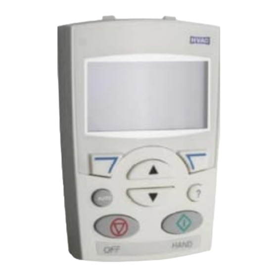
- Page 2 ACH550 Control Panel (ACH-CP-B) & Ethernet Cable – For Control Panel (ACH-CP-B) Interface to control board (SMIO-01). OPCA-01 (DB9 to RJ45 Connector), USB to 232 Connector, & Computer with Drive Windows Light – For Drive Windows Light interface to control board (SMIO-01). Note that this hardware is only required if using Drive Windows Light in place of the control panel.
- Page 3 Step 3: Remove all control wire and fieldbus connection from terminals (you can leave any existing jumpers). Unscrew the board enclosure mounting screw from upper right corner. Step 4: At the bottom of the plastic board enclosure there will be two plastic tabs (on bottom left, one bottom right) that should be pulled down to separate the enclosure.
- Page 4 Step 6: On the back plane of the board and plastic housing push the 4 tabs that hold the board in place away from the control board (SMIO-01). Lift board and slide it out of the plastic cover of board enclosure. Step 7: Remove small ribbon cable connector from control board (SMIO-01).
- Page 5 Step 9: Connect your 24VDC power to the 2 terminals on the 64652745 (OPEX-01 Interface Board) Option A: Gathering the programming data - Panel installation and considerations Step 1: Connect Ethernet cord to RJ45 connector in control panel (ACH-CP-B) and on 64652745 (OPEX-01 Interface Board) *Note: All of the control wiring has been removed, you will encounter alarms and faults when power is applied to the board.
- Page 6 *Note that the base programming for the drive will depend on the macro loaded, so the changed parameters will not reflect a parameter that is part of the default of the macro. Reference the ACH550 manual for macro parameter defaults This solution will support frame sizes 1 through 6.