Siemens Sivacon S8 Planning Information
Show thumbs
Also See for Sivacon S8:
- Operating instructions manual (63 pages) ,
- Instructions manual (12 pages) ,
- Manual (11 pages)
1
2
3
4
Table Of Contents
5
6
7
8
9
10
11
12
13
14
15
16
17
18
19
20
21
22
23
24
25
26
27
28
29
30
31
32
33
34
35
36
37
38
39
40
41
42
43
44
45
46
47
48
49
50
51
52
53
54
55
56
57
58
59
60
61
62
63
64
65
66
67
68
69
70
71
72
73
74
75
76
77
78
79
80
81
82
83
84
85
86
87
88
89
90
91
92
93
94
95
96
97
98
99
100
101
102
103
104
105
106
107
108
109
110
111
112

Related Manuals for Siemens Sivacon S8


Summary of Contents for Siemens Sivacon S8
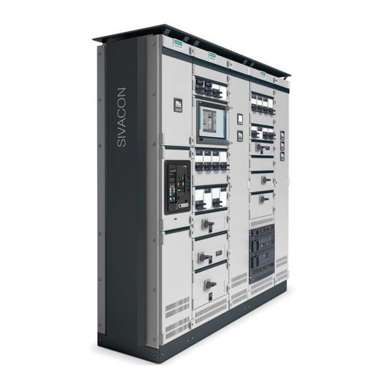
- Page 1 Totally Integrated Power SIVACON S8 Technical Planning Information · 10/2015 www.siemens.com/sivacon-s8...
- Page 3 WARNING, death or severe personal injury may result if proper precautions are not taken. Siemens products may only be used for the applications described in the catalog and in the relevant technical documentation. If products and components from other manufacturers are used, these must be recommended or approved by Siemens.
-
Page 4: Sivacon S8 - System Overview
SIVACON S8 System-based power distribution Technical Planning Information SIVACON S8 – System overview Circuit-breaker design Universal mounting design In-line design, plug-in Cubicles in fixed-mounted design Reactive power compensation Further planning notes Conforming to standards and design-verified Technical annex Glossary and rated parameters... -
Page 5: Table Of Contents
Content System-based power distribution Further planning notes Installation SIVACON S8 – System overview Weights and power loss System configuration and cubicle design Environmental conditions Corner cubicle Conforming to standards and Main busbar, horizontal design-verified Connection points for earthing and The product standard... - Page 6 Chapter 1 System-based power distribution...
-
Page 7: System-Based Power Distribution
We have prepared this planning support for dimensioning electric power distribution sys- manual for the SIVACON S8 low-voltage switchboard to tems and determine the devices and distribution boards support you with this task. Three principles must be ob- required for them. - Page 8 SIMARIS configuration tools Tested safety Configuring and dimensioning a low-voltage switchboard is SIVACON S8 is a synonym for safety at the highest level. very complex. SIVACON S8 switchboards are configured by The low-voltage switchboard is a design-verified low-volt- experts, effectively supported by the SIMARIS configuration...
- Page 9 Advantages of modular design SIVACON S8 can be used at all application levels in the Every SIVACON S8 switchboard is manufactured of de- low-voltage network (Fig. 1/3): mand-oriented, standardised, and series-produced mod- • Power center or secondary unit substation ules. All modules are tested and of a high quality. Virtually •...
- Page 10 Chapter 2 SIVACON S8 – System overview System configuration and cubicle design Corner cubicle Main busbar, horizontal Connection points for earthing and short-circuit devices Overview of mounting designs...
-
Page 11: Sivacon S8 - System Overview
• Economic efficiency - right from the start regards: • Flexibility – through modularity Tab. 2/1: Technical data, standards and approvals for the SIVACON S8 switchboard Standards and approvals Standards and regulations Power switchgear and controlgear assembly IEC 61439-2... - Page 12 Vertical distribution busbar (PE) Ventilated base compartment cover cable connection compartment Ventilated cubicle door Vertical distribution busbar (N) Compartment door cable connection compartment Head room door Fig. 2/1: Cubicle design of SIVACON S8 SIVACON S8 Planning Principles – SIVACON S8 – System overview...
-
Page 13: System Configuration And Cubicle Design
Tab. 2/2: Schematic overview of switchboard configurations for SIVACON S8 Busbar position Rear Bottom Top and bottom Single-front / double-front design Single front Double front Side of connection Operating panel SIVACON S8 Planning Principles – SIVACON S8 – System overview... - Page 14 Chapter 8 “Further planning notes”. • Back to back (only for single-front design) Cable/busbar entry From the bottom From the top Connection in cubicle Front Rear Side of connection Operating panel SIVACON S8 Planning Principles – SIVACON S8 – System overview...
- Page 15 Busbar position Rated current Up to 6,300 A Cable/busbar entry Connection in cubicle Front or rear 1,200 Cable / busbar Device/functional Busbar Cross-wiring Operating connection compartment compartment compartment panels compartment SIVACON S8 Planning Principles – SIVACON S8 – System overview...
- Page 16 Top or bottom Rated current Up to 7,010 A Cable/busbar entry Bottom, top Connection in cubicle Front 1,200 Cable / busbar Device/functional Busbar Cross-wiring Operating connection compartment compartment compartment panels compartment SIVACON S8 Planning Principles – SIVACON S8 – System overview...
- Page 17 Door components with DIN 43656) or upon request 25 mm (layer thickness 100 ± 25 μm) Width 45 mm Design components Blue Green Basic Fig. 2/2: Dimensions of enclosure parts SIVACON S8 Planning Principles – SIVACON S8 – System overview...
-
Page 18: Corner Cubicle
500 mm 600 mm 600 mm 700 mm Corner cubicle 800 mm 900 mm 1,200 mm 900 mm Operation panel Fig. 2/3: Integration of the corner cubicle SIVACON S8 Planning Principles – SIVACON S8 – System overview... -
Page 19: Main Busbar, Horizontal
0,94 for unventilated boards: 0,98 Busbar position rear top or rear bottom Fig. 2/4: Variable busbar position for SIVACON S8 SIVACON S8 Planning Principles – SIVACON S8 – System overview... -
Page 20: Connection Points For Earthing And Short-Circuit Devices
300 mm² cable lugs can be used with M12 screw, Main earthing busbar but this cable lug does not comply with DIN 46235, although it is 600 mm, 1,000 mm supplied by some manufacturers. (MEB) SIVACON S8 Planning Principles – SIVACON S8 – System overview... -
Page 21: Overview Of Mounting Designs
Internal separation Form 1, 2b, 3a, 4b, 4 type 7 (BS) Form 3b, 4a, 4b, 4 type 7 (BS) Form 3b, 4b Busbar position Rear, top Rear, top Rear, top SIVACON S8 Planning Principles – SIVACON S8 – System overview... - Page 22 Front side Front side 1,000, 1,200 mm 600, 800, 1,000 mm 800 mm Form 1, 2b, 3b, 4a, 4b Form 1, 2b Form 1, 2b Rear, top Rear Rear, top, without SIVACON S8 Planning Principles – SIVACON S8 – System overview...
- Page 23 SIVACON S8 Planning Principles – SIVACON S8 – System overview...
- Page 24 Chapter 3 Circuit-breaker design Cubicles with one ACB (3WL) Cubicles with up to three ACB (3WL) Cubicles with one MCCB (3VL) Cubicles for direct supply and direct feeder...
-
Page 25: Circuit-Breaker Design
(ACB) in withdrawable or fixed-mounted design or addition to cable connections, the system also provides alternatively with 3V. moulded-case circuit-breakers (MCCB) design-verified connections to SIVACON 8PS busbar trunk- (Tab. 3/1). ing systems. Fig. 3/1: Cubicles in circuit-breaker design SIVACON S8 Planning Principles – Circuit-breaker design... - Page 26 Also form 4b type 7 in acc. with BS EN 61439-2 possible Information about 3WT circuit-breakers is available from your Siemens contact Information about moulded-case circuit-breakers in plug-in/withdrawable design is available from your Siemens contact The circuit-breaker cubicles allow the installation of a current transformer (L1, L2 and L3) at the customer con- nection side.
-
Page 27: Cubicles With One Acb (3Wl)
2,500 A 1,000 3WL1232 3,200 A 1,000 1,000 1,200 3WL1340 4,000 A 3WL1350 5,000 A 1,200 1,200 3WL1363 6,300 A 1,200 1,200 Withdrawable design, frame height 2,200 mm Main busbar up to 6,300 A SIVACON S8 Planning Principles – Circuit-breaker design... - Page 28 3,200 A 1,400 3WL1340 4,000 A 1,000 1,000 5,000 A 1,400 1,400 3WL1350 3WL1363 6,300 A 1,400 1,400 Withdrawable design, frame height 2,200 mm Main busbar up to 7,010 A Frame height 2,200 mm SIVACON S8 Planning Principles – Circuit-breaker design...
- Page 29 3WL1120 2,000 A 400/600 3WL1220 2,000 A 600/800 rear bottom busbar position 3WL1225 2,500 A 600/800 3WL1232 3,200 A 600/800 3WL1340 4,000 A 1,000 1,000 Frame height 2,200 mm SIVACON S8 Planning Principles – Circuit-breaker design...
- Page 30 Connection to the SIVACON 8PS busbar trunking system is effected by means of an installed busbar trunking connec- tor. The SIVACON S8 connecting system is located com- pletely within the cubicle. The busbars can be connected both from the top and from the bottom, thus allowing flexible connection.
- Page 31 2,650 A 3,510 A 2,700 A 3,700 A 3WL1350 5,000 A 3,660 A 4,720 A 3,310 A 4,460 A 3WL1363 6,300 A 3,920 A 5,180 A 3,300 A 5,060 A SIVACON 8PS system LX SIVACON S8 Planning Principles – Circuit-breaker design...
-
Page 32: Cubicles With Up To Three Acb (3Wl)
• Variant C: highest current for bottom mounting slot, lowest current for top mounting slot Information about an individual distribution of the rated currents in the cubicle is available from your Siemens contact. Tab. 3/9: Rated currents for special load cases of a circuit-breaker cubicle with three 3WL11 circuit-breakers in the cubicle Rated current at 35 °C ambient temperature... -
Page 33: Cubicles With One Mccb (3Vl)
605 A 660 A 3VL7712 1,250 A 890 A 1,100 A 890 A 1,100 A 775 A 980 A 3VL8716 1,600 A 900 A 1,100 A 1,050 A 1,200 A 915 A 1,070 A SIVACON S8 Planning Principles – Circuit-breaker design... -
Page 34: Cubicles For Direct Supply And Direct Feeder
2,930 A 2,210 A 2,930 A 3,200 A 2,340 A 2,280 A 2,910 A 3,390 A 2,770 A 3,390 A 4,000 A 3,430 A 4,480 A 3,300 A 4,210 A 3,140 A 4,210 A SIVACON S8 Planning Principles – Circuit-breaker design... - Page 35 SIVACON S8 Planning Principles – Circuit-breaker design...
- Page 36 Chapter 4 Universal mounting design Fixed-mounted design with compartment door In-line switch disconnectors with fuses (3NJ62 / SASIL plus) Withdrawable design...
-
Page 37: Universal Mounting Design
4 Universal mounting design The universal mounting design of SIVACON S8 switch- designs makes for a space-optimized structure of the boards (Fig. 4/1) allows outgoing feeders in withdrawable switchboard. Tab. 4/1 gives an overview of the general design, fixed-mounted design and plug-in in-line design to cubicle characteristics. - Page 38 The other cubicle characteristics are identical to the cubicle without forced cooling. All mounting designs and func- tional units without forced cooling can be applied. Fig. 4/2: Cubicle with forced cooling for universal mounting design SIVACON S8 Planning Principles – Universal mounting design...
- Page 39 820 A 1,000 A ventilated Rated short-time withstand 65 kA 65 kA 65 kA 65 kA current I (1 sec) Top main busbar position Rated conditional short-circuit current I = 150 kA SIVACON S8 Planning Principles – Universal mounting design...
-
Page 40: Fixed-Mounted Design With Compartment Door
Connection cross sections in fixed-mounted cubicles with Rated current with fuse link = nominal device current a front door Nominal feeder current Max. connection cross section ≤ 250 A 120 mm > 250 A 240 mm SIVACON S8 Planning Principles – Universal mounting design... -
Page 41: In-Line Switch-Disconnectors With Fuses (3Nj62 / Sasil Plus)
Withdrawable unit variants SFD and HFD can be mixed within one cubicle Fig. 4/5: Design variants of the withdrawable units in standard feature design (SFD; left) and high feature design (HFD; right) SIVACON S8 Planning Principles – Universal mounting design... - Page 42 Fig. 4/7: Normal withdrawable unit in SFD with a withdrawable Apart from that, other protocols based on the Industrial Ethernet standard unit height of 100 mm such as Modbus/TCP can be used SIVACON S8 Planning Principles – Universal mounting design...
- Page 43 Number of available auxiliary contacts (rated current 10 A / 250 V) Withdrawable unit Control plug type height Without communication With PROFIBUS With PROFINET 12-pole ≥ 100 mm 24-pole 32-pole ≥ 150 mm 40-pole SIVACON S8 Planning Principles – Universal mounting design...
- Page 44 200 mm ¼ Width Small Connected withdrawable 150 mm, unit 200 mm position ½ Width Normal ≥ 100 mm withdrawable (grid 50 mm) unit Fig. 4/10: Positions in the HFD contact system SIVACON S8 Planning Principles – Universal mounting design...
- Page 45 Apart from that, other protocols based on the EIA-485 (RS485) interface standard such as Modbus RTU can be used Apart from that, other protocols based on the Industrial Ethernet standard such as Modbus TCP can be used SIVACON S8 Planning Principles – Universal mounting design...
- Page 46 Front areas usable for an instrument panel on small withdrawable units with an installation height of 200 mm Height of withdrawable unit > 100 mm Height of withdrawable unit 100 mm Dimensions in mm Fig. 4/13: Front areas usable for an instrument panel on normal withdrawable units SIVACON S8 Planning Principles – Universal mounting design...
- Page 47 Withdrawable unit Control plug type Without height With PROFIBUS With PROFINET communication 26-pole Small withdrawable unit 150, 200 mm 40-pole 12-pole ≥ 100 mm 24-pole Normal withdrawable unit 32-pole ≥ 150 mm 40-pole SIVACON S8 Planning Principles – Universal mounting design...
- Page 48 365 A 405 A Type: ¼ = small withdrawable unit size ¼ Circuit-breaker in vertical mounting position ½ = small withdrawable unit size ½ Rated current with fuse link = nominal device current SIVACON S8 Planning Principles – Universal mounting design...
- Page 49 500 mm 200 kW 600 mm 700 mm 700 mm 250 kW 600 mm 700 mm 700 mm Type: ¼ = small withdrawable unit size ¼ ½ = small withdrawable unit size ½ SIVACON S8 Planning Principles – Universal mounting design...
- Page 50 700 mm Type: ¼ = small withdrawable unit size ¼ Type: ¼ = small withdrawable unit size ¼ ½ = small withdrawable unit size ½ ½ = small withdrawable unit size ½ SIVACON S8 Planning Principles – Universal mounting design...
- Page 51 700 mm Type: ¼ = small withdrawable unit size ¼ Type: ¼ = small withdrawable unit size ¼ ½ = small withdrawable unit size ½ ½ = small withdrawable unit size ½ SIVACON S8 Planning Principles – Universal mounting design...
- Page 52 Chapter 5 In-line design, plug-in In-line switch-disconnectors 3NJ62 with fuses In-line switch-disconnectors SASIL plus with fuses...
-
Page 53: In-Line Design, Plug-In
5 In-line design, plug-in The plug-in design for SIVACON S8 switchboard (Fig. 5/1) Connection is effected directly at the switching device The with switching devices in in-line design with an incom- maximum cable cross sections that can be connected are ing-side plug contact allows easy and fast modification or stated in the device catalogues. -
Page 54: In-Line Switch-Disconnectors 3Nj62 With Fuses
250 mm 320 A 3NJ6233 630 A 200 mm 250 mm 500 A Rated current with fuse link = nominal device current The configuration rules stated in the following are to be observed SIVACON S8 Planning Principles – In-line design, plug-in... - Page 55 630 A 500 A In-line unit Below the bottommost in-line unit, only 50 mm blanking cover instead of 100 mm blanking cover or no blanking cover instead of 50 mm blanking cover required SIVACON S8 Planning Principles – In-line design, plug-in...
-
Page 56: In-Line Switch-Disconnectors Sasil Plus With Fuses
300 mm 324 A 630 A 150 mm 300 mm 510 A Rated current with fuse link = nominal device current The configuration rules stated in the following are to be observed SIVACON S8 Planning Principles – In-line design, plug-in... - Page 57 630 A 510 A In-line unit Below the bottommost in-line unit, only 75 mm blanking cover instead of 150 mm blanking cover or no blanking cover instead of 75 mm blanking cover required SIVACON S8 Planning Principles – In-line design, plug-in...
- Page 58 Chapter 6 Cubicles in fixed-mounted design In-line design, fixed-mounted Fixed-mounted design with front cover Cubicle for customized solutions...
-
Page 59: Cubicles In Fixed-Mounted Design
Design-verified ALPHA small distribution board. Measuring instruments and standard modules guarantee maximum safety. control elements are installed in the door. Fig. 6/1: Cubicles for fixed-mounted in-line design with 3NJ4 in-line switch-disconnectors SIVACON S8 Planning Principles – Cubicles in fixed-mounted design... - Page 60 200 A 220 A 3NJ413 400 A 100 mm 290 A 340 A 3NJ414 630 A 100 mm 380 A 460 A Rated current with fuse link = nominal device current SIVACON S8 Planning Principles – Cubicles in fixed-mounted design...
- Page 61 When using smaller links, a corresponding utilization Max. permissible continuous operational current = (in percent) is permissible. = (380 A / 630 A) x 500 A = 300 A SIVACON S8 Planning Principles – Cubicles in fixed-mounted design...
-
Page 62: Fixed-Mounted Design With
- Mounting kit for modular installation devices - Empty slot, device compartment Cubicle with degree of protection less than or equal to IP31 is also possible without an additional cubicle high door SIVACON S8 Planning Principles – Cubicles in fixed-mounted design... - Page 63 Nominal feeder current Max. conductor cross section ≤ 250 A 120 mm > 250 A 240 mm Fig. 6/4: Cable connections in fixed-mounted cubicles with a front cover SIVACON S8 Planning Principles – Cubicles in fixed-mounted design...
- Page 64 3KL57 400 A 350 mm 350 mm 345 A 355 A 3KL61 630 A 550 mm 550 mm 535 A 555 A Rated current with fuse link = nominal device current SIVACON S8 Planning Principles – Cubicles in fixed-mounted design...
- Page 65 DIN 43880 and a front cover. The multi-profile rail allows the SIKclip 5ST25 wiring system to be snapped on at the back. Fig. 6/5: Mounting kit for modular installation devices (without cover) SIVACON S8 Planning Principles – Cubicles in fixed-mounted design...
-
Page 66: Cubicle For Customized Solutions
Cubicle for customized solutions For individual configuration and flexible expansion of available for SIVACON S8 switchgear (Fig. 6/6). Their gen- cubicles, additional cubicles for customized solutions are eral characteristics are stated in Tab. 6/13 and the configu- ration data are described in Tab. 6/14. - Page 67 2,200 mm 1,800 mm ALPHA 8GK rapid mounting kits Compartment Cubicle height Main busbar Height Width Without 1,800 mm 2,000 mm , 600, 800 mm Rear position 1,650 mm No viewing door SIVACON S8 Planning Principles – Cubicles in fixed-mounted design...
- Page 68 Chapter 7 Reactive power compensation Configuration and calculation Separately installed compensation cubicles...
-
Page 69: Reactive Power Compensation
- With / without main busbar Design options - With connection to main busbar or with external connection - With / without line-side switch-disconnector module as cut-off point between main busbars and vertical distribution bar SIVACON S8 Planning Principles – Reactive power compensation... - Page 70 > 160 Hz audio frequency suppressor depends on the frequency of the ripple control signal of the respective network operator and must be adjusted if required. Special variants are available on request. SIVACON S8 Planning Principles – Reactive power compensation...
-
Page 71: Configuration And Calculation
F and the mean active power consump- tion P Compensation power P = F x P = 0.81 x 75 kW comp Compensation power P = F x P = 60 kvar comp comp SIVACON S8 Planning Principles – Reactive power compensation... - Page 72 – 0.06 0.11 0.21 0.29 0.54 0.48 – 0.06 0.16 0.23 0.48 0.43 0.92 – 0.10 0.18 0.43 0.36 0.94 0.03 0.11 0.36 0.29 0.96 – 0.01 0.29 0.20 0.98 – 0.20 SIVACON S8 Planning Principles – Reactive power compensation...
-
Page 73: Separately Installed Compensation Cubicles
Connection possibility for separately installed compensation cubicles: up to 2 x 240 mm Recommendation for 4 parallel cables per phase: Use separate incoming feeder cubicle and power factor correction cubicle with main busbar. SIVACON S8 Planning Principles – Reactive power compensation... - Page 74 Chapter 8 Further planning notes Installation Weights and power loss Environmental conditions...
-
Page 75: Further Planning Notes
All dimensions refer to the frame dimensions (nominal cubicle size) ! Minimum height of passage under covers or enclosures Fig. 8/1: Clearances to obstacles Fig. 8/2: Maintenance gangway widths and passage heights SIVACON S8 Planning Principles – Further planning notes... - Page 76 Circuit breaker fully withdrawn Door fixed in open position Minimum Escape direction maintenance 500 mm gangway width Unfolded swivel frame behind the door Fig. 8/3: Minimum widths of maintenance gangways in accordance with IEC 60364-7-729 SIVACON S8 Planning Principles – Further planning notes...
- Page 77 With main busbar position at the rear Double-front installations With main busbar position at the rear Double-front units Rear panel Door Fig. 8/4: Cubicle arrangement for single-front (top) and double-front systems (bottom) SIVACON S8 Planning Principles – Further planning notes...
- Page 78 7 x Ø14.8 Foundation frame, Screed e.g. U-shaped section DIN 1026 Bolt Alignment shims Heavy-duty dowel Concrete floor Fig. 8/7: Foundation frame mounted on concrete Fig. 8/10: Mounting points for the corner cubicle SIVACON S8 Planning Principles – Further planning notes...
-
Page 79: Weights And Power Loss
800 mm 600 mm 930 kg 800 mm 1,050 kg Tab. 8/2: Power losses of SIVACON S8 cubicles (orientation values) Power loss (approx. value) P Power loss (approx. value) P Circuit-breaker design with Circuit-breaker design with 100% rated 80 % rated... -
Page 80: Environmental Conditions
In case of higher concentrations of pollutants (Class > 3C2) pollutant reducing measures are required, for example: • Air-intake for service room from a less contaminated SIVACON S8 switchboards are intended for use in the normal environmental conditions described in Tab. 8/3. point •... - Page 81 Tab. 8/4 (for example an excessively low or high value for temperature or air humidity), the measures SIVACON S8 Planning Principles – Further planning notes...
- Page 82 Chapter 9 Conforming to standards and design- tested The product standard IEC 61439-2 Arc resistance Seismic safety and seismic requirements Declarations of conformity and certificates...
-
Page 83: Conforming To Standards And Design-Verified
Conditional ü ü 11. Electromagnetic compatibility (EMC) ü 12. Mechanical function Effectivity of the assembly in case of external faults Only impulse withstand voltage Comparison with an already tested design SIVACON S8 Planning Principles – Conforming to standards and design-verified... -
Page 84: Arc Resistance
SIVACON S8, for example (Fig. 9/1). An arc-resistant zone is defined as part of a circuit where an igniter wire can be applied and... - Page 85 SIVACON S8. be specified if applicable. Tab. 9/3: SIVACON S8 arc levels (system areas to which the internal arc is limited are marked in orange) Assessment criteria for personal safety and system protection...
-
Page 86: Seismic Safety And Seismic Requirements
= floor acceleration (acceleration in the mounting plane of the switchboard) On supporting structure of low stiffness, ZPA = zero period acceleration connected to the building g = ground acceleration = 9.81 m/s SIVACON S8 Planning Principles – Conforming to standards and design-verified... - Page 87 Swiss association of engineers and architects Richter Richter scale Mod. Mercalli Modified Mercalli scale; 1956 Medvedev-Sponheur-Karnik scale; 1964 Fig. 9/3: Comparison of seismic scales for the classification of seismic response categories of SIVACON S8 SIVACON S8 Planning Principles – Conforming to standards and design-verified...
-
Page 88: Declarations Of Conformity And Certificates
Directive 2014/30/EU must be transferred in national law by the EU member states up to the 20th of April, 2016. At that time a new declaration of conformity is provided. SIVACON S8 Planning Principles – Conforming to standards and design-verified... - Page 89 Fig. 9/4: EC-Declaration of Conformity for SIVACON S8 in respect of the Low Voltage and EMC Directives SIVACON S8 Planning Principles – Conforming to standards and design-verified...
- Page 90 Fig. 9/5: Declaration of Conformity for SIVACON S8 regarding design verification SIVACON S8 Planning Principles – Conforming to standards and design-verified...
- Page 91 Fig. 9/6: Declaration of Conformity for SIVACON S8 regarding design verification - Annex Page 1/2 SIVACON S8 Planning Principles – Conforming to standards and design-verified...
- Page 92 Fig. 9/7: Declaration of Conformity for SIVACON S8 regarding design verification - Annex Page 2/2 SIVACON S8 Planning Principles – Conforming to standards and design-verified...
- Page 93 SIVACON S8 Planning Principles – Conforming to standards and design-verified...
- Page 94 Chapter 10 Technical annex 10.1 Power supply systems according to their type of connection to earth 10.2 Loads and dimensioning 10.3 Degrees of protection according to IEC 60529 10.4 Forms of internal separation based on IEC 61439-2 10.5 Operating currents of three-phase asynchronous motors 10.6 Three-phase distribution transformers 100...
-
Page 95: Technical Annex
Earthing of exposed conductive parts R N conductor close to the power source) via protective (separately, in groups or jointly) conductors Fig. 10/1: Systems according to the type of connection to earth in accordance with IEC 60364-1 SIVACON S8 Planning Principles – Technical annex... - Page 96 Neutral choke (no longer required for modern systems) Central Earthing Point Main Equipotential Bonding conductor Fig. 10/2: Line diagram for an earthing concept based on a central earthing point (CEP) SIVACON S8 Planning Principles – Technical annex...
- Page 97 (IT systems). Accordingly, cir- cuit-breaker specifications relating to the IT system must be observed. 3-phase 690 V AC 690 V Fig. 10/3: Double fault in the IT system SIVACON S8 Planning Principles – Technical annex...
-
Page 98: Loads And Dimensioning
... Such apparatus shall be disconnected at one of their terminals unless they are not designed to withstand the full test voltage, in which case all terminals may be disconnected." SIVACON S8 Planning Principles – Technical annex... - Page 99 63 < I 10 mm 800 mm < S ¼ x S S = cross section of phase conductor in mm The neutral current can be influenced by load harmonics to a significant extent. SIVACON S8 Planning Principles – Technical annex...
-
Page 100: Degrees Of Protection According To Iec 60529
Against access to dangerous parts Additional letter (optional) with a back of the hand finger tool wire Supplementary information Additional letter (optional) especially for high-voltage devices movement during water test standstill during water test weather conditions SIVACON S8 Planning Principles – Technical annex... -
Page 101: Forms Of Internal Separation Based On Iec 61439-2
Busbar Enclosure Internal separation Functional unit Legend: Terminal for conductors led to the unit from outside SIVACON S8 Planning Principles – Technical annex... -
Page 102: Operating Currents Of Three-Phase Asynchronous Motors
113 A 132 kW 230 A 184 A 134 A 160 kW 280 A 224 A 162 A 200 kW 350 A 280 A 203 A 250 kW 430 A 344 A 250 A SIVACON S8 Planning Principles – Technical annex... -
Page 103: Three-Phase Distribution Transformers
2,640 A 47,722 A “ uninfluenced initial symmetrical transformer short-circuit current in consideration of the voltage and correction factor of the transformer impedance in accordance with IEC 60909-0, without considering the system source impedance SIVACON S8 Planning Principles – Technical annex... - Page 104 Chapter 11 Glossary and rated parameters 11.1 Terms and definitions 11.2 Rated parameters 11.3 Index of tables 11.4 Index of figures...
-
Page 105: Glossary And Rated Parameters
Construction rule Defined rules for the construction of an assembly which may be applied as an alternative to a verification test SIVACON S8 Planning Principles – Glossary and rated parameters... - Page 106 Maintenance gangway within a PSC assembly Space which is only accessible for authorized persons and which is mainly intended for the maintenance of built-in equipment SIVACON S8 Planning Principles – Glossary and rated parameters...
-
Page 107: Rated Parameters
The circuit must be capable of carrying this current specified conditions, defined in terms of a current and when operated alone without that overtemperatures in time. individual components will exceed the limit values specified. SIVACON S8 Planning Principles – Glossary and rated parameters... - Page 108 Specifically: Pollution degree 3 Conductive pollution occurs or dry, non-conductive pollution occurs which is expected to become con- ductive due to condensation. SIVACON S8 Planning Principles – Glossary and rated parameters...
-
Page 109: Index Of Tables
Rated currents for direct supply and direct feeder with overload relay, type 2 at 50 kA Minimum withdrawable unit sizes for: 4/22 fuseless motor feeders, 400 V, CLASS 10, with SIMOCODE, type 2 at 50 kA SIVACON S8 Planning Principles – Glossary and rated parameters... - Page 110 SIVACON S8 system characteristics under arcing Chapter 6 conditions General cubicle characteristics for fixed-mounted SIVACON S8 arc levels (system areas to which the in-line design internal arc is limited are marked in orange) Rating data of the 3NJ4 cable feeders...
-
Page 111: Index Of Figures
10/2 Double fault in the IT system the right for switch-disconnectors SASIL plus with 10/3 Double fault in the IT system fuses Pluggable in-line switch-disconnectors 3NJ62 Pluggable in-line switch-disconnectors SASIL plus SIVACON S8 Planning Principles – Glossary and rated parameters... - Page 112 All product names may be trademarks or product names of descriptions and/or performance characteristics, which do Siemens AG or supplier companies; use by third parties for not always apply in the form described in a specific appli- their own purposes could violate the rights of the owner.