Siemens SINAMICS G120 Getting Started
Hide thumbs
Also See for SINAMICS G120:
- List manual (1256 pages) ,
- Manual (732 pages) ,
- Operating instructions manual (550 pages)

Related Manuals for Siemens SINAMICS G120


Summary of Contents for Siemens SINAMICS G120
-
Page 1: Getting Started
Warnings and Cautions Installation SINAMICS Check List G120 Control Units Commissioning CU240E Diagnostics Getting Started FW 3.1 10/2007 A5E01301680B AA... - Page 2 This device may only be used for the applications described in the catalog or the technical description and only in connection with devices or components from other manufacturers which have been approved or recommended by Siemens. Correct, reliable operation of the product requires proper transport, storage, positioning and assembly as well as careful operation and maintenance.
-
Page 3: Table Of Contents
Warnings and Cautions Table of contents Warnings and Cautions ..................... 4 Installation ........................ 6 2.1 Installing the Control Unit ..................6 2.2 Terminals ......................10 2.3 Connecting a CU240E via USS ................10 Check List........................11 Commissioning ......................12 4.1 Create a STARTER Project................. 13 4.2 Going Online with the Inverter ................ -
Page 4: Warnings And Cautions
Warnings and Cautions Warnings and Cautions General WARNING This equipment contains dangerous voltages and controls potentially dangerous rotating mechanical parts. Non-compliance with the Warnings or failure to follow the instructions contained in this manual can result in loss of life, severe personal injury or serious damage to property. - Page 5 Warnings and Cautions CAUTION Children and the general public must be prevented from accessing or approaching the equipment! This equipment may only be used for the purpose specified by the manufacturer. Unauthorized modifications and the use of spare parts and accessories that are not sold or recommended by the manufacturer of the equipment can cause fires, electric shocks and injuries.
-
Page 6: Installation
Installation Command and setpoint sources ot the CU240E The inverter is controlled and monitored per default via terminals. Note The command and setpoint sources can be changed in the commissioning procedure or via Parameters P0700 and P1000. Installing the Control Unit The CU controls the functions of the PM. - Page 7 Installation CU240E Getting Started, 10/2007, A5E01301680B AA...
- Page 8 Installation CU240E Block Diagram CU240E Getting Started, 10/2007, A5E01301680B AA...
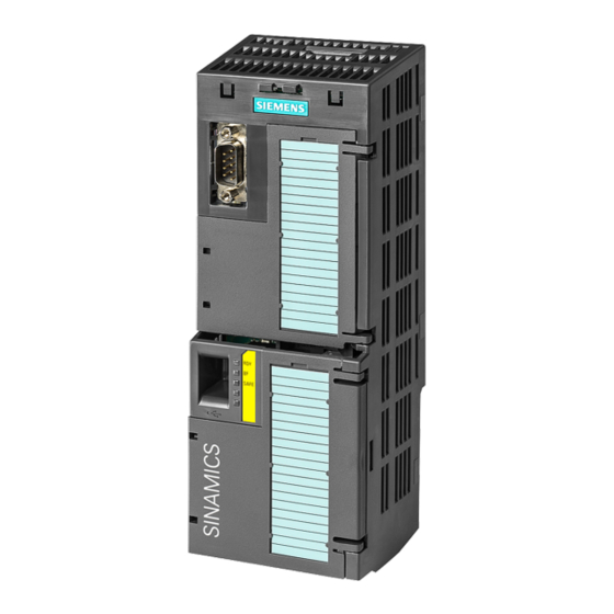
- Page 9 Installation Fitting the Control Unit to the Power Module The Control Unit is snapped onto the Power Module as shown in the figure below. To disconnect the CU push the release button on top of the PM. The process of fitting the Control Unit to the Power Module is the same technique independent from the type of G120 control unit or G120 power module.
-
Page 10: Terminals
Installation Terminals Overview of CU240E Terminals The terminals are designed as cage clamps for cable cross sections from 0.2 mm to 1,5 mm (24 … 14 AWG). The different types are listed below: • Digital Inputs (DI) • Digital Outputs (DO) •... -
Page 11: Check List
Check List Before power is applied to the inverter/motor system, the following checks should be performed: Check that: ✓ The environmental conditions conform to the inverter/motor specifications The inverter and the motor are securely mounted The inverter and motor are correctly installed with adequate cooling provision The motor and the application/equipment are ready to start, i.e. -
Page 12: Commissioning
Commissioning Description When shipped from the factory the G120 inverter (control unit and power module) must not be operated before a commissioning of the inverter has been performed. This can be done via: ● downloading a valid parameter set from BOP or STARTER ●... -
Page 13: Create A Starter Project
For commissioning the inverter you can use the STARTER software, delivered with the PC Connection Kit or download the latest STARTER software version from the internet under the following link: http://support.automation.siemens.com/WW/view/de/10804985/133100 Create a STARTER Project Commissioning procedure ● Switch the supply voltage to the inverter ●... - Page 14 Commissioning Press "Change and test ..." button to set the PG/PC interface. – If "PC COM-Port (USS)" is available as shown in the dialog box "PG/PC interface", press the "properties" button. – If not press the "Select ..." button to install the "PC COM-Port (USS)"...
- Page 15 Commissioning ● Setting properties of the COM port Via this dialog box, you set the com interface (COM1, COM2, COM3) and the Baud rate (default 38400). To find out the right values, select e.g. COM1 and press the "Read" button. If "???" is displayed in the Baud rate test area select another com interface.
- Page 16 Commissioning ● In this dialog you can enter a name for your inverter - in this case "SINAMICS_G120_CU240E" (no blanks or special characters), then press "Continue" and close the following summary dialog via the "Complete" button. CU240E Getting Started, 10/2007, A5E01301680B AA...
-
Page 17: Going Online With The Inverter
Commissioning Going Online with the Inverter Description With the above described procedure the project is created and the following STARTER dialog appears, but there is still no online connection established so far. To go online with this inverter press . The following dialog box shows in the left column the online and in the right column the offline saved data. - Page 18 Commissioning CU240E Getting Started, 10/2007, A5E01301680B AA...
-
Page 19: Start Commissioning
Commissioning Start Commissioning Description With closing the last dialog from the "Going Online Section" the "Offline mode" at the very down in the dialog box changes to "Online mode" and in case of first commissioning the message F00395 appears. It states that no commissioning has been performed so far with the inverter. To confirm, select the message and press the "Acknowledge"... -
Page 20
Commissioning Note Information about the symbols used in STARTER can be found in the online help. Press
and then click at the requested symbol. E.g. If you have confirmed F0395, open the drive unit ( ), double-click the drive object ) and start the wizard for basic commissioning from the following STARTER dialog. - Page 21 Commissioning Now you can select the basic commissioning settings for your application via pull-down menus. With pressing "Continue" button you jump to the next item. In case of "Drive functions" we recommend to select "Identification of all parameters inclusive the saturation curve" as shown in the figure below: CU240E Getting Started, 10/2007, A5E01301680B AA...
- Page 22 Commissioning For calculation of the motor data we recommend to select "Restore factory setting and calculate motor data only" as shown in the dialog box. CU240E Getting Started, 10/2007, A5E01301680B AA...
- Page 23 Commissioning The basic commissioning wizard ends with the following dialog: To complete basic commissioning, the motor data identification, selected during basic commissioning must be performed via switching on the inverter. This can be done via the chosen command source (e.g. terminals, BOP or communication) or via STARTER as shown in the dialog box below.
- Page 24 Commissioning will be displayed. Once Motor data identification has finished, the alarm disappears and the inverter switches OFF ( becomes colored again). CU240E Getting Started, 10/2007, A5E01301680B AA...
- Page 25 Commissioning To set the command source back press "Give up control priority!" in the following dialog box. Take care of the warnings displayed. Now the basic commissioning is finished. To save the settings in the EEPROM of your inverter, select the SINAMICS project and press the "Copy RAM to ROM" button CU240E Getting Started, 10/2007, A5E01301680B AA...
- Page 26 Commissioning Commissioning the application Now you can commission your application via the dialog boxes of the drive navigator or via the functions in the navigation area. If you have performed the application commissioning, disconnect your PC from the inverter via .
-
Page 27: Factory Reset
Commissioning This selection performs in addition to disconnecting the PC form the inverter the following steps: : saves project on your PC : saves drive settings on your PC (Upload) : Saves data from inverter RAM to EEPROM Factory reset Description With a factory reset a defined initial state of all of the inverter parameters can be re- established. -
Page 28: A Diagnostics
Diagnostics Fault s and alarms A fault indicates a severe unfavorable state of the inverter. If a fault occurs, the inverter is powered down with an OFF2 command and the LED "SF" on the Control Unit is active. Faults must be acknowledged before the inverter can be switched on again. An alarm states that the inverter is ●... - Page 29 Diagnostics Fault Cause Remedy F00072 USS setpoint fault Check USS master F00090 Encoder feedback loss Check that the encoder is installed and commissioned correctly. F0395 The fault occurs after a CU/PM swap or startup clone. It can also be cause by a faulty read from the EEPROM.
- Page 30 Diagnostics Status display via LEDs The SINAMICS G120 inverters provide multiple functions and operating states which are indicated via LEDs. Colors The colors of the LEDs are self explanatory. The Status of the inverter is displayed by the following different LED colors and states:...