Table of Contents
IGNITION CONTROLS FOR COMBINED VALVE AND IGNITION SYSTEM
NOTE:
The Combined Valve and Ignition (CVI) product concept consists of a specially designed gas valve family in
combination with a dedicated ignition controls family. This product handbook describes the CVI ignition controls family
S4565, S4575 and S4585 for use in combination with the CVI gas control family VK41.. For details of the CVI gas
controls please refer to Product Handbook EN2R-9004. For an up-to-date copy please contact your nearest
Honeywell office. For glossary of terms, abbrevations and symbols see document EN2R-9039
Distribuitor: CALOR SRL
Str. Progresului nr. 30-40, sector 5, Bucuresti
tel: 021.411.44.44, fax: 021.411.36.14
www.calorserv.ro - www.calor.ro
S4565, S4575 AND S4585
APPLICATION
The Combined Valve and Ignition (CVI) system has been
developed for application in gas fired domestic central
heating boilers, combi boilers and warm air furnaces or water
heater appliances with an automatic ignition system.
For this system, the S4565, S4575 and S4585 ignition
controls are used in conjunction with the VK41.. series gas
controls to provide and optimised safety sub-system for
programmed safe light up and flame supervision of the main
burner of the appliance
The combined system then provides programmed safe light
up, flame supervision and regulation of gas flow to the main
burner and/or pilot burner of the appliance.
1
PRODUCTION HANDBOOK
EN2R-9031 0402R15-NE
Table of Contents

Related Manuals for Honeywell S4565


Summary of Contents for Honeywell S4565
- Page 1 This product handbook describes the CVI ignition controls family S4565, S4575 and S4585 for use in combination with the CVI gas control family VK41.. For details of the CVI gas controls please refer to Product Handbook EN2R-9004. For an up-to-date copy please contact your nearest Honeywell office.
-
Page 2: Table Of Contents
Dimensional drawing “old style” housing Accessories for degree of protection IP 20, IP 40, IP X4, IP 44 Assembling of IP X4/44 housing Application S4565/S4575/S4585 ignition controls S4565 ignition controls Specifications S4565A, B ,P, Q System operation S4565A, B, P, Q... -
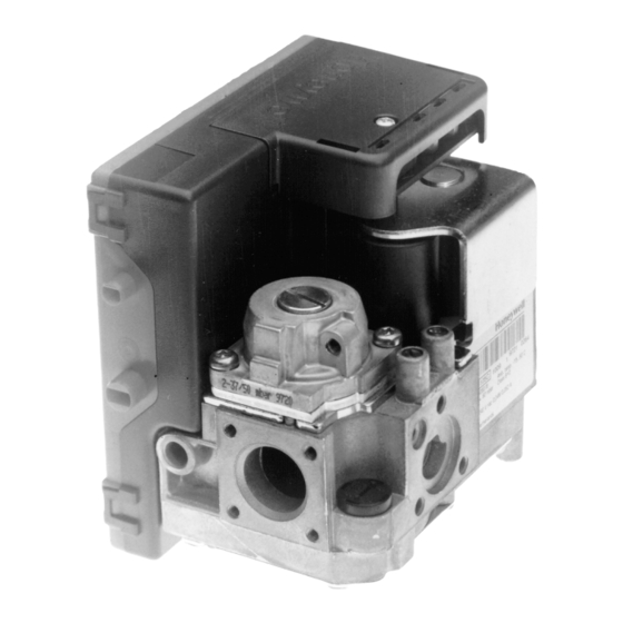
Page 3: Description
The CVI consists of a gas valve of the VK41.. series and a sequence. dedicated ignition control of the series S4565, S4575 and • S4585 which is connected directly on to it. -
Page 4: Features
FEATURES General Electrical connection options • • All burner control safety functions concentrated in one Connection to the gas control is made entirely by reliable and optimized system. plugging the ignition control on. • • Specially designed to provide the optimum system Electric connections are positioned on top and are made solution in gas appliances with a DBI or IP system to light by a multiple plug-in connector (IP 20 enclosure if side... -
Page 5: Dimensional Drawing Housing
DIMENSIONAL DRAWING HOUSING Connector pins suitable for Molex 3001 female connectors Mounting hole Ø 3.2 Ignition Flame detection Note: specific housings may deviate from drawing Fig. 1. Dimensional drawing housing in mm EN2R-9031 0402R15-NE... -
Page 6: Dimensional Drawing "Old Style" Housing
DIMENSIONAL DRAWING “OLD STYLE” HOUSING Connector pins suitable for Molex 3001 female connectors Mounting hole Ø 3.2 18.5 Ignition Flame detection Note: specific housings may deviate from drawing Fig. 2. Dimensional drawing “old style” housing in mm (do not use for new designs) EN2R-9031 0402R15-NE... -
Page 7: Accessories For Degree Of Protection Ip 20, Ip 40, Ip X4, Ip 44
ACCESSORIES FOR DEGREE OF PROTECTION IP 20, IP 40, IP X4, IP 44 See also Replacement parts and Accessories on page 66. IP 00 IP 20 IP 40 IP X4 IP 44 Optional strain relief Order number: 45900442-007 or- 011: 45900440-001 ( screws included) Cover set with separate strain relief Order number: 45900440-001 (screws included) -
Page 8: Assembling Of Ip X4/44 Housing
ASSEMBLING OF IP X4/44 HOUSING Assembling of the cable connector(s) and cover (see Fig. 3. and Fig. • Use cable with Ø 5 ... Ø 7 mm. • Strip length cable: 15 mm • Grommet inlet nunmbers1, 2, 4 applicable for cable with Ø... -
Page 9: Application S4565/S4575/S4585 Ignition Controls
In S4565 series there are versions available for both Direct Burner Ignition (DBI) and Intermittent Pilot (IP) ignition systems with a defined safety ignition time. - Page 10 SPECIFICATIONS S4565A, B ,P, Q Model Timing (depending on O.S. number) Suffix A: atmospheric, direct burner ignition Self check time (T 1.5 s Suffix B: atmospheric, direct burner ignition, Waiting time (T 0 ...30 s flame relay output Safety time (T 3.5 ...
- Page 11 CONNECTION DIAGRAM S4565A, B ,P, Q Optional Side connections Optional Optional ** * See note 3. ** See page 21. Fig. 19. All versions Fig. 6. Connection diagram S4565A, B, P and Q EN2R-9031 0402R15-NE...
-
Page 12: System Operation S4565A, B, P, Q
SYSTEM OPERATION S4565A, B, P, Q General Suffix A, B, P and Q (see Fig. 7.) When there is a call for heat a self check period (Tc) plus Lock-out reset waiting period (T ) elapse before built-in igniter and gas valve The S4565A, B, P and Q ignition controls can be reset by are switched on. - Page 13 TIMING DIAGRAM S4565A, B, P, Q Fig. 7. Timing diagram S4565A, B, P and Q EN2R-9031 0402R15-NE...
-
Page 14: Specifications S4565C, D, R, T
SPECIFICATIONS S4565C, D, R, T Model Housing (degree of protection) Suffix C: fan assisted, direct burner ignition See: Suffix D: fan assisted, intermittent pilot burner ignition accessories for degree of protection page 7.. including safety timer replacement parts and accessories page 66.. Suffix R: as C except volatile lock-out Timing (depending on O.S. - Page 15 CONNECTION DIAGRAM S4565C, D, R, T Side connections** Optional See note 7. ** Alternative side connection for models with combined flame de- tection/high voltage. See page 56. Fig. 71. Fig. 8. Connection diagram S4565C, D, R and T EN2R-9031 0402R15-NE...
-
Page 16: System Operation S4565C, D, R, T
SYSTEM OPERATION S4565C, D, R, T General Suffix D and T (see Fig. 10.) When there is a call for heat the fan starts running through Lock-out reset the no air position of the air proving switch. The S4565C, D, R, T ignition controls can be reset by either If an external LPG valve is connected, this will be energized. - Page 17 TIMING DIAGRAM S4565C, D, R, T Fig. 9. Timing diagram S4565C and R Fig. 10. Timing diagram S4565D and T EN2R-9031 0402R15-NE...
-
Page 18: Specifications S4565Ad, Bd, Cd, Dd, Pd, Qd, Rd, Td "1000" Series
SPECIFICATIONS S4565AD, BD, CD, DD, PD, QD, RD, TD “1000” SERIES Model Housing (degree of protection) Suffix AD: atmospheric, direct burner ignition See: Suffix BD: as AD but with flame relay output accessories for degree of protection page 7.. Suffix CD: fan assisted, direct burner ignition replacement parts and accessories page 66.. - Page 19 CONNECTION DIAGRAM S4565AD, BD, CD, DD, PD, QD, RD, TD “1000“ SERIES Side connections ** Optional Optional Optional *** See note 10. ** See page 21. Fig. 17. *** See page 21. Fig. 19. Fig. 11. Connection diagram S4565AD and BD “1000” series Side connections ** Optional Optional...
- Page 20 Side connections ** Optional Optional *** See note 10. ** See page 21. Fig. 17. *** See page 21. Fig. 19. Fig. 13. Connection diagram S4565CD and DD “1000” series Side connections Optional Optional *** See note 10. *** See page 21. Fig. 19. Fig.
- Page 21 Side connections ** Optional Optional *** See note 10. ** See page 21. Fig. 17. *** See page 21. Fig. 19. Fig. 16. Connection diagram S4565RD and TD “1000” series Side connections Side connection Fig. 17. Alternative side connection in case of sparking Fig.
-
Page 22: System Operation S4565Ad, Bd, Cd, Dd, Pd, Qd, Rd, Td "1000" Series
SYSTEM OPERATION S4565AD, BD, CD, DD, PD, QD, RD, TD “1000” SERIES General Suffix BD and QD (see Fig. 21.) The S4565AD, BD, CD, DD, PD, QD, RD, TD ignition controls As AD and PD except flame relay contact or opto is closed can provide both closed-loop sparking and sparking to after flame detection. - Page 23 TIMING DIAGRAM S4565AD, BD, CD, DD, PD, QD, RD, TD “1000” SERIES Fig. 20. Timing diagram S4565AD, PD “1000” series Fig. 21. Timing diagram S4565BD and QD “1000” series EN2R-9031 0402R15-NE...
- Page 24 Fig. 22. Timing diagram S4565CD and RD “1000” series Fig. 23. Timing diagram S4565DD and TD “1000” series EN2R-9031 0402R15-NE...
-
Page 25: Specifications S4565Ad, Bd, Cd, Dd, Pd, Qd, Rd, Sd, Td "2000" Series
SPECIFICATIONS S4565AD, BD, CD, DD, PD, QD, RD, SD, TD “2000” SERIES Model Housing (degree of protection) Suffix AD: atmospheric, direct burner ignition See: Suffix BD: as AD but with flame relay output accessories for degree of protection page 7.. Suffix CD: fan assisted, direct burner ignition replacement parts and accessories page 66.. - Page 26 CONNECTION DIAGRAM S4565AD, BD, CD, DD, PD, QD, RD, TD “2000” SERIES Side connections * Optional Optional ** See page 29. Fig. 31. ** See page 21. Fig. 19. h, RS and alarm are optional Fig. 24. Connection diagram S4565AD and BD “2000” series Side connections * Optional Optional **...
- Page 27 Side connections * Optional Optional ** ** See page 29. Fig. 31. See page 29. Fig. 31. *** See page 21. Fig. 19. ** See page 21. Fig. 19. RS and alarm are optional RS and alarm are optional Fig. 26. Connection diagram S4565CD and DD “2000” series Side connections * Optional Optional **...
- Page 28 Side connections * Optional Optional ** See page 29. Fig. 31. and Fig. ** See page 21. Fig. 19. Alarm is optional Fig. 29. Connection diagram S4565RD and TD “2000” series Side connections Void valves ignition used Fig. 30. Connection diagram S4565SD “2000” series EN2R-9031 0402R15-NE...
- Page 29 Side connections Side connections Fig. 31. Alternative side connection in case of sparking Fig. 33. Alternative side connection in case of combined to ground flame sensing and sparking Side connections Side connection Fig. 32. Alternative side connection in case of combined flame sensing and sparking (single rod) Fig.
-
Page 30: System Operation S4565Ad, Bd, Cd, Dd, Pd, Qd, Rd, Sd, Td "2000" Series
SYSTEM OPERATION S4565AD, BD, CD, DD, PD, QD, RD, SD, TD “2000” SERIES General Suffix CD and RD (see Fig. 37.) The S4565AD, BD, CD, DD, PD, QD, RD, TD ignition controls When there is a call for heat, self check period (T ) plus can provide both closed-loop sparking and sparking to waiting period (T... - Page 31 TIMING DIAGRAM S4565AD, BD, CD, DD, PD, QD, RD, TD “2000” SERIES Fig. 35. Timing diagram S4565AD, PD “2000” series Fig. 36. Timing diagram S4565BD, QD “2000” series EN2R-9031 0402R15-NE...
- Page 32 Fig. 37. Timing diagram S4565CD, RD “2000” series Fig. 38. Timing diagram S4565DD, TD “2000” series EN2R-9031 0402R15-NE...
-
Page 33: Specifications S4565Af, Bf, Cf, Df, Pf, Qf, Rf, Tf
SPECIFICATIONS S4565AF, BF, CF, DF, PF, QF, RF, TF Model Housing (degree of protection) Suffix AF: atmospheric, direct burner ignition See: Suffix BF: atmospheric, intermittent pilot burner ignition accessories for degree of protection page 7.. including safety timer replacement parts and accessories page 66.. Suffix CF: fan assisted, direct burner ignition Timing (depending on O.S. - Page 34 CONNECTION DIAGRAM S4565AF, BF, CF, DF, PF, QF, RF, TF Side connections** Optional See note 17. ** Alternative side connection for models with combined flame detection/high voltage. See page 56. Fig. 71. Fig. 39. Connection diagram S4565AF, BF, PF and QF Side connections** Optional See note 17.
-
Page 35: System Operation S4565Af, Bf, Cf, Df, Ef, Pf, Qf, Rf, Tf
SYSTEM OPERATION S4565AF, BF, CF, DF, EF, PF, QF, RF, TF General Suffix CF and RF (see Fig. 43. When there is a call for heat the fan starts running through Lock-out reset the no air position of the air proving switch after a self check The S4565AF, BF, CF, DF, EF, PF, QF, RF and TF ignition period (T ) plus a waiting period (T... - Page 36 TIMING DIAGRAM S4565AF, BF, CF, DF, EF, PF, QF, RF, TF Fig. 41. Timing diagram S4565AF and PF stab Fig. 42. Timing diagram S4565BF and QF EN2R-9031 0402R15-NE...
- Page 37 Fig. 43. Timing diagram S4565CF and RF stab Fig. 44. Timing diagram S4565DF and TF EN2R-9031 0402R15-NE...
-
Page 38: Application Note S4565Bf With Second Main Valve Control
APPLICATION NOTE S4565BF WITH SECOND MAIN VALVE CONTROL Lock out Gas valve Flame Side connections** main valve Optional See note 17. ** Alternative side connection for models with combined flame detection/high voltage. See page 56. Fig. 71. Fig. 45. Connection diagram S4565BF with second main valve control 1 MV 2 MV stab... -
Page 39: Application Note S4565Df, Tf With External Main Burner Interrupt
APPLICATION NOTE S4565DF, TF WITH EXTERNAL MAIN BURNER INTERRUPT Side connections** CNY 17-3 Optional See note 17. ** Alternative side connection for models with combined flame detection/high voltage. See page 56. Fig. 71. Fig. 47. Connection diagram S4565DF, TF with external main burner interrupt in fan assisted applications External main burner interrupt Ignition is switched off after a predetermined extended Maximum open contact voltage 24 V... - Page 40 stab Fig. 48. Timing diagram S4565DF and TF with external main burner interrupt in fan assisted applications Side connections** CNY 17-3 Optional See note 17. ** Alternative side connection for models with combined flame detection/high voltage. See page 56. Fig. 71. Fig.
- Page 41 stab Fig. 50. Timing diagram S4565DF and TF with external main burner interrupt in atmospheric applications EN2R-9031 0402R15-NE...
-
Page 42: Specifications S4565Pv, Qv, Rv, Tv
SPECIFICATIONS S4565PV, QV, RV, TV General Timing (depending on O.S. number) The S4565PV, QV, RV, TV are multitrial volatile ignition Self check time (T 0 ... 2 s controls in accordance with EN 298. The S4565RV and TV Waiting time (T 0 ... - Page 43 CONNECTION DIAGRAM S4565PV, QV, RV, TV Side connections * Status output or relay contact Optional ** See page 44. Fig. 55. ** See page 44. Fig. 56. Fig. 51. Connection diagram S4565PV and QV series or connection diagram S4565RV and TV series wired in atmospheric applications Side connections * Status output or relay contact...
- Page 44 Side connections * Status output or relay contact Optional ** See page 44. Fig. 55. ** See page 44. Fig. 56. Fig. 53. Connection diagram S4565RV and TV with prepurge option Side connections Side connections Fig. 54. Alternative side connection in case of combined Fig.
-
Page 45: System Operation S4565Pv, Qv, Rv, Tv
SYSTEM OPERATION S4565PV, QV, RV, TV General After T the fan starts running. The S4565PV, QV, RV, TV ignition controls can provide When sufficient air flow is proven by the air proving switch, closed-loop sparking, sparking to ground or combined the built-in igniter and gas valve are switched on. - Page 46 STATUS OUTPUT APPLICATION The lock-out status data from the S4565PV, QV, RV, TV The status information can be found under chapter ignition controls can be read by the microprocessor in the SPECIFICATIONS paragraph:“Opto coupler status output” comfort boiler control and stored in its EEPROM. on page 41 If the signal of the status output does not correspond to the The relay contact is controlled by the microprocessor and...
- Page 47 TIMING DIAGRAM S4565PV, QV, RV, TV Number of retrials Fig. 59. Timing diagram S4565PV series Number of retrials Fig. 60. Timing diagram S4565QV series EN2R-9031 0402R15-NE...
- Page 48 Number of retrials Fig. 61. Timing diagram S4565RV series Number of retrials Fig. 62. Timing diagram S4565TV series EN2R-9031 0402R15-NE...
- Page 49 Number of retrials Fig. 63. Timing diagram S4565RV with prepurge Number of retrials Fig. 64. Timing diagram S4565TV with prepurge EN2R-9031 0402R15-NE...
- Page 50 SPECIFICATIONS S4575A, B, P, Q Model Flame sensing Suffix A: atmospheric, direct burner ignition Min flame current: Suffix B: as A but with flame relay output for optional phase 0.5 µA Suffix P: as A except volatile lock-out independent versions: Suffix Q: as B except volatile lock-out for phase dependent...
- Page 51 CONNECTION DIAGRAM S4575A, B, P, Q Side connections 24 ... 240 V Optional Optional * See page 21. Fig. 19. Reset switch and alarm are optional Fig. 65. Connection diagram S4575A, B, P and Q Side connections 24 ... 240 V Optional Optional * See page 21.
-
Page 52: System Operation S4575A, B, P, Q
SYSTEM OPERATION S4575A, B, P, Q General Suffix B and Q (see Fig. 68.) The S4575A, B, D, P ignition controls can provide hot surface As suffix A and P except flame relay contact is closed after ignition. flame detection. The Hot Surface Igniter (HSI is connected to a floating Gas/air application winding of a transformer (see figFig. - Page 53 TIMING DIAGRAM S4575A, B, P, Q Fig. 67. Timing diagram S4575A, P Fig. 68. Timing diagram S4575B, Q EN2R-9031 0402R15-NE...
- Page 54 SPECIFICATIONS S4585D Model Flame sensing 1.0 ∝A Suffix D: fan assisted, intermittent pilot burner ignition Min flame current: Response time on: > 0.2 s Response time off (T < 1.0 s Supply voltage Phase-Phase mains 220 ... 240 Vac, 50/60 Hz (-15%, +10%) trafo input: 220 ...
- Page 55 CONNECTION DIAGRAM S4585D Side connections** Optional ** Alternative side connection for models with combined flame detection/high voltage. See page 56. Fig. 71. Fig. 69. Connection diagram S4585D wired up in atmospheric application Side connections** Optional LM - Limiter Air proving switch NF - No flame indicator Alternative side connection for models with combined...
- Page 56 Side connection ignition control 230 Vac Special applications input S7030 Ignition transformer Fig. 71. Alternative side connection for models with Fig. 72. Alternative side connection for models with combined flamedetection/high voltage using AT7030A flame sense input + 230Vac output for external ignition flame detection transformer.
-
Page 57: System Operation S4585D
SYSTEM OPERATION S4585D Atmospheric ignition control S4585D (see Fig. 73.) Fan assisted ignition control S4585D (see Fig. 73.) After false flame check during self check time (T ) a built-in When there is a call for heat, fan is energized through no air igniter and pilot gas valve are switched on. - Page 58 TIMING DIAGRAM S4585D Fig. 73. Timing diagram S4585D EN2R-9031 0402R15-NE...
-
Page 59: General Considerations
WARNING proving switch should be appropriate for the load that is switched by the ignition control. Honeywell is not responsible for damage, injury due NOTE 23.: Power interruptions will cause program restart. to mis wiring. After installation the ignition control can become wet due to condensation. -
Page 60: Emc Guidelines
EMC GUIDELINES The ignition cable has to be determined for lowest emission. Do not lead ignition cable close to other cabling. To suppress Radio Frequency Interference (RFI) the ignition control including spark igniter cabling should be mounted in sufficient shielded environment. EN2R-9031 0402R15-NE... -
Page 61: Electrical Connections And Wiring
• Wiring between ignition control and spark sensing probe should have good quality insulation, suitable for the Flame sensing wiring temperatures encountered. The S4565/S4575 and S4585 ignition controls are equiped CAUTION CAUTION with flame sensing by ionisation current based on the flame rectification principle. -
Page 62: Quality Assurance Statement
Assembly processes are guided by work instructions. Patrol and certified Quality System. inspections form part of the assembly processes. The quality system is described in the Honeywell Combustion Assembly inspection is performed by employees of the Controls Center Quality Assurance Programme and its quality control department, using their own authorised related operational procedures and instructions. -
Page 63: Standards And Approvals
O.S. numbers only. However conformity can only be declared as part of the appliance. The S4565/S4575 ignition controls are approved on the North American standard ANSI Z21.20 Automatic Ignition For other O.S. numbers, additional suppression means may be needed within the appliance. -
Page 64: Ordering Information
• The correct pilot burner for the installation concerned: NOTE: An up-to-date product survey, with details of all refer to Honeywell ignition products guide EN0R-0038. new and existing products in these series, is • Order numbers of replacement parts and accessories available. -
Page 65: Overview Ignition Controls
OVERVIEW IGNITION CONTROLS Model Suffix Application Safety time Atmospheric Fan assisted Flame relay Lock-out or flame opto output S4565 Non volatile S4565 Non volatile S4565 Volatile S4565 Volatile S4565 Non volatile S4565 Non volatile S4565 Non volatile S4565 Non volatile... -
Page 66: Replacement Parts And Accessories
Description Packing quantity Ordernumber Molex cable for 45.900.419-023 S4565A,B,P,Q Molex cable for 45.900.419-029 S4565C,D,R,T Molex cable for 45.900.419-025 S4585D Molex cable for 45.900.419-022 S4565AD,BD,DD,PD,QD,RD,SD,TD Molex cable for 45.900.419-024 S4565C,D,R,T and S4565AF,BF,CF,DF,EF,PF,QF,RF,TF Molex cable for: 45.900.419-033 S4565AD,BD,DD,PD,QD,RD,TD “2000-series” S4565BM,DM S4565PV.QV,RV,TV and S4575A,B,P,Q Molex cable for 45.900.419-034 S4565AD and PD “2000”...