Honeywell Lyric LCP300-L Installation And Reference Manual
Hide thumbs
Also See for Lyric LCP300-L:
- User reference manual (68 pages) ,
- Quick installation manual (8 pages) ,
- Manual (2 pages)
Table of Contents
Quick Links
See also:
Manual
Table of Contents

Related Manuals for Honeywell Lyric LCP300-L


Summary of Contents for Honeywell Lyric LCP300-L
- Page 1 PLEASE GO TO THE PAGE 34 FOR FCC/IC AGENCY STATEMENTS Lyric Installation and Reference Guide Gateway Ref: LCP300-L/LCP300-LC 800-21666 10/16 Rev. A...
- Page 2 The security system is not designed for use with any device that may be attached to the system's control or other communicating bus if Honeywell has not approved such device for use with the system. Use of any such unauthorized device may cause damage or compromise the performance of the security system and affect the validity of the end user’s Honeywell...
-
Page 3: Table Of Contents
Lyric Gateway Installation and Reference Guide Table of Contents System Features ......................................5 Installing the Control ....................................7 Battery Installation ......................................7 Battery Selection ..................................... 7 Installing the Rechargeable Backup Battery ..........................7 Replacing the Rechargeable Backup Battery ..........................7 Wall Mounting ........................................ - Page 4 This system supports Lyric Lock, an advanced feature designed to keep it functioning optimally. Lyric Lock capabilities include: the ability to interact with Honeywell and your company’s network for the setup and programming of system features, support for remote software updates and the ability (when enabled) to enhance the end user’s security by preventing unauthorized takeover of the system by another monitoring...
-
Page 5: System Features
Lyric Gateway Installation and Reference Guide System Features The Lyric Gateway is a self-contained, rechargeable wireless control/communicator that features easy installation and usage. A built-in speaker provides voice annunciation of system status along with voice descriptors of each zone. An internal module allows the controller to communicate with the Central Station via the Internet or (if installed) Cellular Wireless. - Page 6 Lyric Gateway Installation and Reference Guide System Features (Continued) System Power • Primary Power: Plug-in Power Supply, 110VAC to 9VDC, 2.5A output p/n 300-04705V1 (300-4063V1 in Canada) • Backup Battery: Rechargeable Nickel-metal Hydride Battery Pack rated at 7.2Vdc. (p/n 300-03864-AIO or 300-03866-AIO Alarm Output •...
-
Page 7: Battery Installation
Lyric Controller Installation and Reference Guide Installing the Gateway Battery Installation The Lyric Gateway is equipped with an integral, replaceable, rechargeable battery pack rated at 7.2Vdc. In the event of an AC power loss, the system is supported by the long life backup battery that is supervised for connection and for low voltage conditions. -
Page 8: Wall Mounting
Lyric Gateway Installation and Reference Guide Installing the Gateway (Continued) Disconnect the battery pack connector from the receptacle on the back of the gateway. Open the hinged battery retainer. Remove the battery pack from the Gateway. Install the replacement battery Install a replacement battery pack (LCP500-4B [p/n 300-03864-AIO] OR LCP500-24B [p/n 300-03866- AIO]) into the gateway. -
Page 9: Desktop Mounting
Lyric Gateway Installation and Reference Guide Installing the Gateway (Continued) Desktop Mounting NOTE: When selecting a location for the Lyric Gateway, be sure to provide a separation of at least 10 feet between 2.4GHz devices such as Wi-Fi Routers/Access Points. The desk Stand can be installed in two positions that provide a viewing angle of 30 degrees or 60 degrees. -
Page 10: Ac Power
Lyric Gateway Installation and Reference Guide Installing the Control (Continued) AC Power The Lyric Gateway is powered by a 110VAC, 60 Hz/9 Volt DC, 2.5 Amp Plug-in Power Supply, 300-04705V1 (300-04063V1 in Canada). Refer to the wiring table below for wire gauge and length. Use only the 300-04705V1 (300-04063V1 Canada) Power Supply. -
Page 11: Communications Modules
Lyric Gateway Installation and Reference Guide Installing the Gateway (Continued) The LYRIC-CDMA Communications Module is only available in the continental United States, Alaska and Hawaii. Communication Modules The Lyric Gateway supports Central Station reporting using wireless/cellular and WiFi communications devices. They also support upload/download programming capability via the Internet. -
Page 12: Checking Signal Strength
Lyric Gateway Installation and Reference Guide Installing the Gateway (Continued) Communication Modules Checking Signal Strength When choosing a suitable mounting location, check the communications module’s signal strength to ensure proper operation. For most installations, using the module’s internal antenna, mounting the Lyric Gateway as high as practical, and avoiding large metal components provides adequate signal strength for proper operation. -
Page 13: Wireless Zones
Lyric Controller Installation and Reference Guide Wireless Zones General Information Zones The Lyric Gateway supports up to 64 total wireless zones using 5800 and SiX™ Series transmitters, and wireless keys. Range The built-in RF receiver can detect signals from wireless transmitters within a nominal range of 200 feet. Transmitters 5800 and SiX™... -
Page 14: Rf Transmitter Loop Numbers
Lyric Gateway Installation and Reference Guide Wireless Zones (Continued) RF Transmitter Loop Numbers (Refer to this information when programming 5800 Series transmitters) The following illustration shows the compatible transmitters, their associated input types and loop designations. Notes: (1) The 5806W3 smoke detector must be used in SIA applications. (2) Button type devices send only fault and low battery signals;... -
Page 15: Mechanics Of Programming
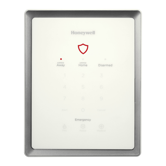
Lyric Controller Installation and Reference Guide Mechanics of Programming Navigating Gateway Keypad Gateway’s keypad can be used for Basic Security Functions. The keypad provides a number of functions and indicators. The System Status Shield is lit Green when the system is ready or flashes Red when it is not. When the system is armed the System Status Shield is lit Red. -
Page 16: Touch-Screen Display
Lyric Gateway Installation and Reference Guide Mechanics of Programming (Continued) Touch-screen Display The MyHome Gateway App is used to display screens on the smart device touch-screen. Variable icons and text are displayed on “screens”. The screen displays status icons and associated text, the current time and date, system status information and menu choices. -
Page 17: Security Screen
Lyric Controller Installation and Reference Guide Mechanics of Programming (Continued) Navigating Menus Security Screen System Status is displayed at the top of each screen and the time and date are displayed at the top left side of the Security Screen. The Security Screen displays the system status and selection “icons”. -
Page 18: Programming
Lyric Gateway Installation and Reference Guide Mechanics of Programming (Continued) Programming If the system is Armed or in Alarm, the Tools icon will not be functional. The system must first be disarmed. Master User Features SCREEN ACTION Select the “Security” icon. Select “Tools”... -
Page 19: Zone Response Type Definitions
Lyric Controller Installation and Reference Guide Zone Response Type Definitions General Information During programming, you must assign a zone type to each zone, which defines the way in which the system responds to faults in that zone. Zone types are defined below. Type Function Characteristics... - Page 20 Lyric Gateway Installation and Reference Guide Zone Response Type Definitions (Continued) Type Function Characteristics Can be assigned to any wireless zone used • Alarm sound will pulse (Temporal Fire) when this zone type is Fire with as a fire zone. Fire with verification is Verification alarmed and the alarm has been verified.
-
Page 21: System Operation
Lyric Controller Installation and Reference Guide System Operation Key/Touchscreen Operation Touchscreen icons displayed on the Smart Device allow the user to arm and disarm the system, and perform other system functions, such as bypassing zones. Zone and system conditions (alarm, trouble, bypass) are displayed on the LCD. -
Page 22: Reset Master Code
Lyric Gateway Installation and Reference Guide System Operation Reset Master Code After Entering the Programming Mode, select “Users” from the Master User screen menu. Select “Master” followed by “Edits’ to reset the Master User Code. Select “User Code”. Enter a new Master Code on the displayed keypad, then select “Done”. The system returns to the previous screen. -
Page 23: System Displays
Lyric Controller Installation and Reference Guide System Operation System Displays The following icons will be displayed on the Home screen along with specific zone status information (if applicable) to indicate system status. DISPLAY DEFINITION DISPLAY DEFINITION DISPLAY DEFINITION AC Loss 901 Expansion Temperature Module Tamper... -
Page 24: Audio Alarm Verification (Two-Way Voice Feature)
Lyric Gateway Installation and Reference Guide System Operation (Continued) Audio alarm verification has not been evaluated by ETL. Audio Alarm Verification (Two-Way Voice Feature) This feature allows the Central Station operator to listen, talk to or conduct a two-way conversation with an individual(s) at the premises. -
Page 25: Event Log
Lyric Controller Installation and Reference Guide System Operation Event Log The Lyric Gateway Series event log is capable of recording and displaying up to 6,000 system events. These events are stored locally in the Gateway, in chronological order, and transmitted to the Central Station. When the maximum number of events is reached in the Event Log, the system will overwrite the oldest event first. -
Page 26: Contact Id Event Log Codes
Lyric Gateway Installation and Reference Guide System Operation Contact ID® Event Log Codes Definition CID Code Event Log Display Resident Monitor Zone Response Resident Monitor Zone Response Resident Response Zone Response Resident Response Zone Response General Monitor Zone Response General Monitor Zone Response General Response Zone Response General Response Zone Response 1401... -
Page 27: Testing The System
Lyric Controller Installation and Reference Guide Testing the System TO THE INSTALLER Regular maintenance and inspection (at least annually) by the installer and frequent testing by the user are vital to continuous satisfactory operation of any alarm system. The installer should assume the responsibility of developing and offering a regular maintenance program to the user as well as acquainting the user with the proper operation and limitations of the alarm system and its component parts. -
Page 28: Zone Discovery Mode
Lyric Gateway Installation and Reference Guide Testing the System (Continued) RF Sniffer Test Mode This mode is used to verify that all transmitters have been properly programmed. Sniffer Mode does not automatically expire. You must manually exit Sniffer Mode to return to normal operation. Go-No-Go Test Mode Conducting this test with your hand wrapped around the transmitter will cause inaccurate results. -
Page 29: Programming Default Values
Lyric Controller Installation and Reference Guide Programming Default Values Programming Field Options Programmed Default System Alarm Report Delay No delay, 15 Seconds, 30 Seconds, 45 Seconds 30 Seconds Burglary Alarm Sound Yes, No Daylight Savings Time Yes, No Time Zone Offset (UTC-5:00 Eastern Time (US &... - Page 30 Lyric Gateway Installation and Reference Guide Programming Default Values Programming Field Options Programmed Default Use DHCP Yes, No NIC IP Address Up to 12 digits 255.255.255.255 Subnet Mask Up to 12 digits 255.255.255.255 Gateway IP Address Up to 12 digits 255.255.255.255 DNS Server IP Address Up to 12 digits...
- Page 31 Lyric Controller Installation and Reference Guide Programming Default Values (Continued) For Zone Programming Options refer to Explanation of Zone Assignment Table Headings Zone Loop Device Alarm Zone Response Type Chime Supervision Type Report Night Descriptor Door Entry Exit 1 Standard Supervised Front Door...
- Page 32 Lyric Gateway Installation and Reference Guide Programming Default Values (Continued) Explanation of Zone Assignment Table Headings Loop Number - Used with 5800 Devices. Entries are 1-4, depending on device being used. Refer to the transmitter’s instructions or the figure provided for appropriate loop numbers. Device Type- Dependent upon the Zone Number being programmed.
-
Page 33: Zone Response Type Matrix
Lyric Controller Installation and Reference Guide Zone Response Type Matrix SiX™ Series Device Signal Strength Signal strength for the enrolled SiX Series Devices is displayed on the Zone Programming Screen for the individual Zone that is programmed. Signal strength information is provided below. Icon Description Signal Strength... -
Page 34: Regulatory Agency Statements
Lyric Gateway Installation and Reference Guide Regulatory Agency Statements Federal Communications Commission (FCC) Part 15 The user shall not make any changes or modifications to the equipment unless authorized by the Installation Instructions or User's Manual. Unauthorized changes or modifications could void the user's authority to operate the equipment. CLASS B DIGITAL DEVICE STATEMENT NOTE: This equipment has been tested and found to comply with the limits for a Class B digital device, pursuant to part 15 of the FCC Rules. - Page 35 Lyric Controller Installation and Reference Guide WARNING THE LIMITATIONS OF THIS ALARM SYSTEM While this System is an advanced design security system, it does not offer guaranteed protection against burglary, fire or other emergency. Any alarm system, whether commercial or residential, is subject to compromise or failure to warn for a variety of reasons.
-
Page 36: Agency Notices
Lyric Gateway Installation and Reference Guide Agency Notices For Residential Burglar Alarm installations with line security, total exit delay time must not exceed 60 seconds. For Burglar Alarm installations without line security, total exit delay time must not exceed 120 seconds. -
Page 37: Specifications
110VAC, 60 Hz/9 Vdc from plug-in 2.5A power supply Rechargeable Backup Battery: Nickel-metal hydride battery pack rated at 7.2 Vdc Communication: Formats Supported: ADEMCO Contact ID® Reporting, 10 characters/sec SIA/DCS Format, 2225Hz Handshake, Data Tones, 2025/2235Hz, baud For patent information, see www.honeywell.com/patents - 37 -... -
Page 38: Glossary
Lyric Gateway Installation and Reference Guide Glossary AES – Advanced Encryption Standard APL – Advanced Protection Logic dBM – decibels milliwatt (power ratio) CDMA - Code Division Multiple Access is a channel access method used by various radio communication technologies that allows many users to occupy the same time and frequency allocations in a given band/space. DHCP –... -
Page 39: Contacting Technical Support
Note the proper model number of this product, and the version level (if known) along with any documentation that came with the product. • Note your Honeywell customer number and/or company name. Having this information handy will make it easier for us to serve you quickly and effectively. Technical Support : ...................... -
Page 40: Index
Lyric Gateway Installation and Reference Guide – Index – 24-Hour Silent ............22 User Security Code ..........22 300-03864-AIO ............7 Master User Tools Screen ........17 300-03866-AIO ............7 Memory of Alarm ............22 300-04063V1 .............. 10 Navigating Menus ..........15, 17 300-04705V1 .............. - Page 41 Lyric Controller Installation and Reference Guide LYRIC GATEWAY RESIDENTIAL BURGLAR AND FIRE ALARM CONTROL PANEL SUMMARY OF CONNECTIONS Notes: Connection of the fire alarm signal to a fire alarm headquarters or a Central Station shall be permitted with the approval of the local authority having jurisdiction. The burglar alarm signal shall not be connected to a police emergency number.
- Page 42 For the latest warranty information, please go to: www.honeywell.com/security/hsc/resources/wa. MyWebTech Warranty Patents For patent information, see www.honeywell.com/patents 2 Corporate Center Drive, Suite 100 P.O. Box 9040, Melville, NY 11747 Copyright © 2016 Honeywell International Inc. www.honeywell.com/security Ê800-21666UŠ 800-21666 10/16 Rev. A...