Table of Contents
(USER'S OPERATION/MAINTENANCE EDITION)
Copyright C
Hitachi High-Technologies Corporation 2014.
All rights reserved. Printed in Japan.
INSTRUCTION MANUAL
MODEL TM3030Plus
TABLETOP MICROSCOPE
・Before using the instrument, read the safety instructions and
precautions carefully.
・Be sure to follow the instructions and warning of instruction manual
and warning label.
・Keep this manual in a safe place nearby so it can be referred to
whenever needed.
FOR
May/2016 5th Edition
Part No. 55E-8881-4 HR-G (HMS)
Table of Contents

Related Manuals for Hitachi TM3030 Plus


Summary of Contents for Hitachi TM3030 Plus
- Page 1 ・Be sure to follow the instructions and warning of instruction manual and warning label. ・Keep this manual in a safe place nearby so it can be referred to whenever needed. Copyright C Hitachi High-Technologies Corporation 2014. May/2016 5th Edition All rights reserved. Printed in Japan. Part No. 55E-8881-4 HR-G (HMS)
- Page 2 NOTICE: 1. Information contained in this document is subject to change without notice for improvement. 2. This manual is copyrighted by Hitachi High-Technologies Corporation with all rights reserved. No part of this manual may be reproduced, transmitted or disclosed to a third party in any form or by any means without the express written permission of Hitachi High-Technologies Corporation.
-
Page 3: Preface
Hitachi’s service department or technicians certified by the same. Carefully read the safety tips provided in this manual, and use the system after you have thoroughly understood the safety precautions (“Safety Tips”... - Page 4 First, please read the sections on “IMPORTANT” and “For the Safe Handling of the System” provided at the beginning of this Instruction Manual. List of Abbreviations Abbreviations that appear frequently in this Instruction Manual and their full spellings are given below: Personal Computer High Voltage...
-
Page 5: Important
Product Warranty Product Warranty Hitachi High Technologies Corporation (“HHT”) warrants that the Model TM3030Plus Tabletop Microscope is free of defect, either in material or manufacturing, based on the specifications provided in this Instruction Manual, provided that the system is used in compliance with the contents of the Instruction Manual. - Page 6 A system failure arising from the corrosion of its electrical circuits or deterioration of its optical elements due to the use of the system under a strongly corrosive atmosphere, such as chlorine gas, or in a dusty environment. A system failure arising from the use of hardware, software, or supplies that are not provided by HHT.
-
Page 7: Installation, Relocation, And After Service
Third-Party Intellectual Property HHT disclaims any liability for claims made by a third party, such as on products made by using a system delivered by HHT or an affiliate thereof, or on patents owned by a third party with respect to the use of a delivered system. -
Page 8: Workshop And Training For Customers
Workshop and Training for Customers For the safe and accurate use of the system, HHT provides workshop and training, either at HHT’s facility or on an on-site visit basis. For procedures for receiving such training, please consult the sales department that handles your account (it will be on a charge basis). System Life The life length of the system is seven (7) years from the commencement of its use, provided that the system is properly maintained in terms of the periodic maintenance and inspection,... -
Page 9: Miscellaneous
Miscellaneous Leaked X-Rays In the Model TM3030Plus Tabletop Microscope, the effective dose equivalent of leakage X-ray radiation is less than 0.1 µSv/hour under its actual operating conditions, which satisfies the requirement specified in the IEC61010-1 Ed 3:2010 In the ICRP recommendations, it is stated that electron microscopes, along with home television sets, fall into a category of potential radiation sources that could produce undesired byproduct X-rays. - Page 10 Open source software license We are using Open source software and show its license and copyright below. libjpeg (ijg-6b) "This software is based in part on the work of the Independent JPEG Group." "The Graphics Interchange Format(c) is the Copyright property of CompuServe Incorporated.
- Page 11 Copyright (c) 1998, 1999 Glenn Randers-Pehrson, and are distributed according to the same disclaimer and license as libpng-0.96, with the following individuals added to the list of Contributing Authors: Tom Lane Glenn Randers-Pehrson Willem van Schaik libpng versions 0.89, June 1996, through 0.96, May 1997, are Copyright (c) 1996, 1997 Andreas Dilger Distributed according to the same disclaimer and license as libpng-0.88, with the following individuals added to the list of Contributing Authors:...
- Page 12 Reference Library, even if advised of the possibility of such damage. Permission is hereby granted to use, copy, modify, and distribute this source code, or portions hereof, for any purpose, without fee, subject to the following restrictions: 1. The origin of this source code must not be misrepresented. 2.
- Page 13 zlib (1.1.4) /* zlib.h -- interface of the 'zlib' general purpose compression library version 1.1.4, March 11th, 2002 Copyright (C) 1995-2002 Jean-loup Gailly and Mark Adler This software is provided 'as-is', without any express or implied warranty. In no event will the authors be held liable for any damages arising from the use of this software.
-
Page 14: For The Safe Handling Of The System
For the Safe Handling of the System Before using the Tabletop Microscope, carefully read the safety precautions provided below, and please be sure to understand them thoroughly. Precautions on human safety are displayed using the following headers combining the safety alert symbol and the phrases “WARNING”... - Page 15 For the Safe Handling of the System When using the chemical such as the reagent, confirm properties of the material and information on handling (MSDS etc.) and handle it properly. If any problem arises with respect to the system, please contact the Sales Department that handles your account or a maintenance service company designated by HHT.
-
Page 16: General Precautions On Safety
For the Safe Handling of the System General Precautions on Safety Notes that have not been described in the instruction manual are shown below. WARNING Accident by using the device continuously with abnormal condition If an abnormal noise, a strange odor, or the generation of fumes occurs when the system is being used, immediately turn it off, and unplug the power cord from the outlet. - Page 17 For the Safe Handling of the System Warnings Provided in the Instruction Manual Notes that have been described to the manual and their description places are shown as follows. WARNING Use in humid and dusty place Do not use the system near a sink, a humidifier, or any place near water, in a humid basement room, or a dusty place or a place subject to fumes.
- Page 18 For the Safe Handling of the System Warnings Provided in the Instruction Manual (continued) WARNING Injury by heavy load The system is a heavy object weighing approximately 65 kg (For Manual Stage) / 68 kg (For Motor drive Stage). Install the system on a table with a minimum load bearing capacity of 100 kg.
- Page 19 For the Safe Handling of the System Warnings Provided in the Instruction Manual (continued) CAUTION Injury from Being Pinched The specimen stage weighs approximately 5 kg. It might cause injury when operating it grasping the parts other than the handle. When changing specimens, securely grasp the handle, and use caution so that your hands will not be pinched.
-
Page 20: Warning And Caution Labels On The System
For the Safe Handling of the System WARNING and CAUTION Labels on the System The warning and caution labels affixed on the Tabletop Microscope are shown on pages SAFETY-7 to SAFETY-8. Check the contents of the warning and caution labels against the actual equipment. Inspect the warning and caution labels from time to time. - Page 21 For the Safe Handling of the System WARNING and CAUTION Labels on the System (continued) WARNING WARNING Hazardous voltage inside Can cause death or severe injury. Do not remove the cover. Hazardous voltage inside P/N 52E-4125 Can cause death or severe injury. Do not remove the cover.
-
Page 22: To Avoid Serious Property Damage Or Damage To The System
For the Safe Handling of the System To Avoid Serious Property Damage or Damage to the System NOTICE About the Power Supply Make sure the power supplied to the Tabletop Microscope is AC 100-240 V (Min. 90 V, Max. 250 V), 500 VA or higher (50/60 Hz). Voltage fluctuations and superposed noise on the power line can adversely affect the main unit. -
Page 23: About Turbo Molecular Pump
For the Safe Handling of the System To Avoid Serious Property Damage or Damage to the System (continued) NOTICE About Turbo Molecular Pump This instrument has a built-in Turbo Molecular Pump (TMP) whose fan rotor spins rapidly (90,000 rpm) to maintain a vacuum inside the specimen chamber. So, any excessive shock might damage TMP. -
Page 24: On The Power Supply For The Pc
For the Safe Handling of the System To Avoid Serious Property Damage or Damage to the System (continued) NOTICE On the Power Supply for the PC If power is shut off during access to the hard disk or other memory devices, a PC malfunction can occur and the data and software stored on them can be destroyed. -
Page 25: About The Computer Virus
For the Safe Handling of the System To Avoid Serious Property Damage or Damage to the System (continued) NOTICE About the Computer Virus If a program or data suddenly becomes corrupt, an unexpected operation occurs, or an abnormal screen appears, the infection of the PC by a computer virus must be suspected. The computer virus refers to a malicious program that surreptitiously invades the PC, runs the PC uncontrollably, or damages data. -
Page 26: About Network Connection
For the Safe Handling of the System To Avoid Serious Property Damage or Damage to the System (continued) NOTICE About Network Connection For network connection, the PC is equipped with an Ethernet port. As connecting to the network through the use of Ethernet requires sufficient knowledge on the network environment, perform such a connection by consulting your network administrator. -
Page 27: For The Proper Use Of The System While Avoiding Minor Damage To It
For the Safe Handling of the System For the Proper Use of the System While Avoiding Minor Damage to It Installing the Control Application If the control application is installed using a privilege other than the administrator privilege, when a user logs in by using power user or general user privileges, the control application may fail to run properly. -
Page 28: Precautions On Operating The System
For the Safe Handling of the System For the Proper Use of the System While Avoiding Minor Damage to It (continued) Precautions on Operating the System When leaving the system unattended, turn off the Start button. Do not use large quantities of chemicals (such as conducting paste) that fix specimens onto the specimen stub. - Page 29 (For Korea only) (한국대상) Information about the attached chemical substances 부속화학물질에 관한 정보 The attached chemical substances listed below do not correspond to the standard of classification of the harmful factor under the laws of Korea. 첨부된 아래의 리스트의 화학물질은 산업안전보건법 시행 규칙 별표 11 의 2 제 1 호에...
-
Page 30: Table Of Contents
Contents PREFACE ..........................1 ABOUT THIS INSTRUCTION MANUAL ................1 IMPORTANT ....................IMPORTANT-1 Product Warranty .................... IMPORTANT-1 Installation, Relocation, and After Service ............IMPORTANT-3 Workshop and Training for Customers ............IMPORTANT-4 System Life ..................... IMPORTANT-4 Disposal ......................IMPORTANT-4 Miscellaneous ....................IMPORTANT-5 For the Safe Handling of the System ............ - Page 31 About Magnetic Fields Generated by a Notebook PC ........SAFETY- 15 About the Temperature and Humidity of the Room ........SAFETY- 15 (For Korea only) Information about the attached chemical substances ..SAFETY- 16 PRECAUTIONS ON HANDLING ............... PRECAUTIONS-1 1. Precautions on Using the System ............PRECAUTIONS-1 2.
- Page 32 About TM3030Plus Setup CD-ROM (Brief Explanation / Summary) ...... 2- 66 2.6.1 Installing the Application ................2- 67 2.6.2 Upgrading the Application ................2- 68 2.6.3 Output Log Data ..................2- 69 2.6.4 About TM3030Plus Application ..............2- 69 2.6.5 Exit ......................
- Page 33 4.3.6 Setting Menu ..................... 4- 54 4.3.7 Stage Menu ....................4- 59 4.3.8 Maintenance Menu ..................4- 62 4.3.9 Help Menu ....................4- 63 4.3.10 Start / Stop Button ..................4- 64 4.3.11 View Mode Selection Button ..............4- 66 4.3.12 Observation Condition Selection Button ...........
- Page 34 Beam Axis Alignment .................... 5- 11 Condenser Lens Aperture Replacement ..............5- 21 Objective Aperture Replacement ................5- 25 Error Messages ..................... 5- 29 5.5.1 Messages Displayed When the Application is Started ........ 5- 29 5.5.2 Initial Startup Window (During Initialization) ..........5- 31 5.5.3 Normal Observation Screen ..............
- Page 35 7.17.1 Measurement of Distance ............... 7- 48 7.17.2 Measurement on Profile View ..............7- 50 7.18 Fix Function ......................7- 53 7.18.1 Image Fix 3 points .................. 7- 53 7.18.2 Image Fix 9 points .................. 7- 56 7.18.3 Profile Fix ....................7- 58 7.19 Saving .........................
-
Page 36: Precautions On Handling
PRECAUTIONS ON HANDLING For safety, please comply with the following precautions: 1. Precautions on Using the System WARNING (1) Do not remove the cover from the main unit. Maximum voltages of AC 240 V and DC 15 kV prevail inside the main unit, potentially causing severe injury or death from electric shock when touched. -
Page 37: Precautions On Operating The System
3. Emergency Action 3a. Turn off the POWER switch located on the main unit. 3b. Unplug the power cord from the outlet. 3c. Contact a service engineer. 4. Precautions on Operating the System 4a. When leaving the system unattended, turn off the accelerating voltage. 4b. -
Page 38: Specifications And Installation Conditions
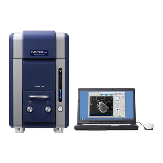
1 SPECIFICATIONS AND INSTALLATION CONDITIONS 1.1 Overview The TM3030Plus is a tabletop microscope for the fine specimen image observation by irradiating the specimen with the narrow-focused electron beam, and detecting secondary electron and backscattered electron so as to be magnified and displayed on screen. The main feature of this system is observation ability with high-magnification which cannot be done with the optical microscope and it permits to get three-dimensional images with great focal depth. -
Page 39: Features
1.2 Features TM3030Plus has the following main features: 1. A compact desktop type. 2. Provides a great focal depth and permits high magnification observation when compared with an optical microscope. 3. Elimination of cumbersome preparation of samples. 4. The capacity to mount specimens up to 70 mm across and 50 mm thick. 5. -
Page 40: Specifications
1.3 Specifications Table 1.3 Specifications Item Product Specifications Accelerating voltage 5 kV, 15 kV Magnification 15x to 60,000x (image display magnification: 43steps (*1)) (digital zoom 2x, 4x), The minimum magnification depends on the accelerating voltage, D (*2), and the screen size. Maximum specimen 70 mm (diameter) size... -
Page 41: Recommended Pc Specifications
1.4 Recommended PC Specifications Table 1.4 Recommended PC Specifications Item Details Recommended PC specifications ® Windows 7 Professional (64 bit) ® CPU: Intel Core™ i5-2520M (or greater) Memory capacity: 2 GB minimum Display resolution: WXGA 1366 × 768 pixels (1677 million colors) Display: 15-inch screen Interface connector: USB2.0/3.0 PC-card slots (IEEE 1394 (6 pin) or Oxford... -
Page 42: Installation Condition
1.5 Installation Condition Install the TM3030Plus in the place of the following condition: Table 1.5 Installation Conditions Item Installation Conditions General 1. Flat location requirements 2. Avoid liquids 3. Avoid external shock 4. Avoid heat sources 5. Avoid strong magnetic field (vertically from system: 15 mT, horizontally from system: 5 mT)... - Page 43 Noise Meet the following noise level for the installation site. The allowable level is defined as the amount of image blurring is 0.2 mm or less in photography at a magnification of 5,000x. Allowable noise level (*) 75 dB or less (frequency 150 Hz) [C characteristics: 72 dB or less (frequency ...
- Page 44 WARNING: The system is a heavy object weighing approximately 65 kg (For Manual Stage) / 68 kg (For Motor drive Stage). Install the system on a table with a minimum load bearing capacity of 100 kg. Installing it on a table with an inadequate load bearing capacity can cause the table to break, which can result in unexpected injury beyond damage to the system.
- Page 45 For layout, see Figure 1.5 below. Power supply & grounding Grounded power cable Diaphragm pump USB cable * Recommended Table layout Notebook PC power cable (2.5 m) Main unit 1200 Units: mm Recommended table size: 1200(W)×800(D)×700(H) mm Minimum table size: 1000(W)×800(D)×700(H) mm Withstand load: 100 kg or more * The Chair is not included in the size * Dimensions is reference...
-
Page 46: Items To Be Prepared
1.6 Items to be Prepared Before the installation of TM3030Plus, prepare the following items. Table 1.6 Customer-provided Items Recommended PC (Refer to 1.4 Recommended PC Specifications) Table Recommended table Size: 1,200 mm (W) × 800 mm (D) × 700mm (H) or larger Withstand load: not less than 100 kg Others: Flat, No casters Others... -
Page 47: Installation And Setup
2 INSTALLATION AND SETUP 2.1 Connecting to the PC Connect the main unit and a PC as shown in the figure below. 1. Connect the USB cable coming from the main unit to the PC USB port. Figure 2.1 Connecting a USB Cable to the PC 2. - Page 48 Click Figure 2.2.1-1 Start Button Window 2. Select [Small icons] from [View by] pull-down menu of [Control Panel]. Click Figure 2.2.1-2 Adjust your computer’s settings Window 2 - 2...
- Page 49 3. The following window appears. Click the [Personalization] icon. Click Figure 2.2.1-3 Adjust your computer’s settings Window 4. Scroll down and click the [Windows 7 Basic] icon. Scroll down Figure 2.2.1-4 Change the visuals and sounds on your computer Window 2 - 3...
- Page 50 5. The window becomes black-and-white in a few seconds and recovers. Confirm the [Windows color] becomes [Windows 7 Basic] and the [Screen saver] becomes [None]. Click Figure 2.2.1-5 Change the visuals and sounds on your computer Window NOTE : TM3030Plus application program is recommended to be used with the setting mentioned above.
- Page 51 7. The following window appears. Click of the [Show additional plans] to select [High performance], and click [Change plan settings]. Figure 2.2.1-7 Select a power plan Window 8. The [Change settings for the plan: High performance] menu is displayed. Select [Never] in the [Dim the display], [Turn off the display] and [Put the computer to sleep] items.
- Page 52 9. Back to the [Power Options], and click [Choose what closing the lid does]. Click Figure 2.2.1-9 Select a power plan Window 10. The following window appears. Change the setting of [On battery] and [Plugged in] for [When I press the power button] to [Shut down]. Change the setting of [On battery] and [Plugged in] for [When I close the lid] to [Do nothing].
- Page 53 NOTE : When this application is running, do not use the screen saver or do not leave the PC in the sleep or standby mode. If any of these actions are taken, USB communication will be disrupted on Windows and application may not work normally or image data may be lost during capturing.
- Page 54 12. The following window appears. Click [Set custom text size (DPI)]. Click Figure 2.2.1-13 Make it easier to read what’s on your screen Window 13. Confirm the setting is same as bellow (9 point Segoe UI at 96 pixels per inch. Scale to this percentage of normal size: 100%) and click the [OK] button.
- Page 55 15. Confirm the setting is the same as bellow, and click the [OK] button. Display: 1.Mobile PC Display Resolution: recommended size of arranged PC Orientation: Landscape Figure 2.2.1-16 Change the appearance of your display Window In the case of using English as a Display language for TM3030Plus application, please operate the settings below.
- Page 56 Click Figure 2.2.1-17 Adjust your computer’s settings Window 18. The Region and Language window appears. Select [Administrative] tab and click [Change system locale] button in the [Language for non-Unicode programs]. Figure 2.2.1-18 Region and Language Window 19. The Region and Language Settings window appears. From the pull down list of [Current system locale], select [English (United States)] and click the [OK] button.
- Page 57 Figure 2.2.1-19 Region and Language Settings Window 20. The following window appears. Click the [Restart now] button. Figure 2.2.1-20 Change System Locale Window 21. After restarting, open the [Administrative] tab in the Region and Language window and confirm that the [Language for non-Unicode programs] is [English (United State)]. 2 - 11...
-
Page 58: Installation Of The Tm3030Plus Application Program
Figure 2.2.1-21 Region and Language Window NOTE : If not performing the above settings, texts may be corrupted in the TM3030Plus application. This is the end of the PC setup. About installation of TM3030Plus application program, refer to 2.3.1 Installation of the Application Program. 2.3 Installation of the TM3030Plus Application Program NOTE : When installing the application, follow these precautions: 1. - Page 59 1. Turn on the PC and log in as “TM3030PlusUSER”. If no other user login name is set additionally, the login window does not appear. 2. Insert the TM3030Plus setup CD-ROM into the CD/DVD drive. 3. The following window appears. Click the [Run SETUP.exe] icon. Figure 2.3-2 AutoPlay Window 2 - 13...
- Page 60 4. TM3030Plus Setup Tools starts automatically. If the User Account Control window appears, click the [Yes] button. Click Figure 2.3-3 User Account Control Window 5. The following window appears. Input Serial Number of the TM3030Plus in the dialog box and click the [OK] button. Serial Number is listed on the product nameplate located on the back of the main unit.
-
Page 61: Installation Of The Application Program
2.3.1 Installation of the Application Program 1. The following window appears. Click the [Installation for TM3030Plus application] button. Click Figure 2.3.1-1 TM3030Plus Setup Tools Window (Main Menu) 2. The following window appears. Click the [Installation of application program.] button. Click Figure 2.3.1-2 TM3030Plus Setup Tools Window (Installation) 2 - 15... - Page 62 NOTE : When this application is already installed, the message window shown below appears. In this case, click the [OK] button to close the window. When any application failure occurs and so the application is to be repaired, refer to 2.5.1 2 Repairing.
- Page 63 5. The following window appears. Click the [Next] button. Click Figure 2.3.1-6 InstallShield Wizard Window 6. The following window appears. Input a User Name and Organization. The items saved before will be displayed by default. In this case, they can be used without changed. Click the [Next] button.
- Page 64 7. The following window appears. Click the [Install] button. Click Figure 2.3.1-8 Ready to Install the Program Window 8. The following window appears, and the application program starts to be installed. Do not click the [Cancel] button during this installation. Figure 2.3.1-9 Installing TM3030Plus Window 2 - 18...
- Page 65 9. When installing, the following [Windows Security] window may appear. In such a case, click the [Install] button. Click Figure 2.3.1-10 Windows Security Window 10. The following window appears. Click the [OK] button. Figure 2.3.1-11 Attach Your Device Window 11. When the install process is completed, the following window appears. Click the [Finish] button.
-
Page 66: Installation Of The Instruction Manual
2.3.2 Installation of the Instruction Manual 1. The following window appears. Click the [Installation for TM3030Plus application] button. Figure 2.3.2-1 TM3030Plus Setup Tools Window (Main Menu) 2. Install the instruction manual. Select [Installation of the instruction manuals] from the Installation menu of the TM3030Plus Setup Tools. Click Figure 2.3.2-2 TM3030Plus Setup Tools Window (Installation) 2 - 20... - Page 67 NOTE : When this Instruction Manual is already installed, the window shown below appears. In this case, click the [OK] button to close the window. After uninstalling the Instruction Manual, re-install it. For the details of the uninstall process, refer to 2.4.2 Uninstallation of the Instruction Manual.
- Page 68 5. The following window appears. Click the [Next] button. Click Figure 2.3.2-6 InstallShield Wizard 6. The following window appears. Click the [Next] button. Click Figure 2.3.2-7 Customer Information Window NOTE : For using with all login user, select [Anyone who uses this computer (all users)] as [Install this application for].
- Page 69 7. The following window appears. Click the [Install] button. Click Figure 2.3.2-8 Ready to Install the Program Window 8. The instruction manual starts to be installed. Do not click the [Cancel] button during this installation. Figure 2.3.2-9 Installing TM3030Plus Manual Window 2 - 23...
- Page 70 9. When the install process is completed, the following window appears. Click the [Finish] button. Click Figure 2.3.2-10 InstallShield Wizard Completion Window 2 - 24...
-
Page 71: Setup Of The System Files
2.3.3 Setup of the System Files 1. The following window appears. Click the [Installation for TM3030Plus application] button. Figure 2.3.3-1 TM3030Plus Setup Tools Window (Main Menu) 2. Setup the System Files. Select [Setup of system files] from the Installation menu of the TM3030Plus Setup Tools. - Page 72 3. After finishing the installation, the following window appears. Click the [OK] button. Figure 2.3.3-3 System Installed Window 4. Click the [Exit] button in the [TM3030Plus Setup Tools] window. Click Figure 2.3.3-4 TM3030Plus Setup Tools Window (Installation) 5. Take out the setup CD-ROM from the CD/DVD drive. NOTE : Keep the TM3030Plus setup CD-ROM at hand because factory default system data is saved in it.
-
Page 73: Confirmation Of The Installation
2.3.4 Confirmation of the Installation 1. Confirm the [TM3030Plus] shortcut icon exists on the desktop. Figure 2.3.4-1 TM3030Plus Shortcut Icon 2. Confirm the [TM3030Plus] is added in the program menu of the [Start] button. Figure 2.3.4-2 Confirmation of Installation 3. Substantial application file is installed in the [C:¥Program Files(x86) ¥ TM3030Plus ¥ ] folder. -
Page 74: Installation Of The Usb Driver Software
2.3.5 Installation of the USB Driver Software Perform the following operations after installation of TM3030Plus application. 1. Shut down the main unit. Connect the USB cable coming from the main unit to the PC USB port. USB cable Main unit Figure 2.3.5-1 Connecting the Main Unit and the PC 2. -
Page 75: Confirmation Of The Usb Driver Software
2.3.6 Confirmation of the USB Driver Software 1. Open [Device Manager] from [Control Panel] of the [Start] menu. Figure 2.3.6-1 Device Manager Icon * When [Device Manager] does not appear, select [Small icons] from [View by] pull-down menu of [Control Panel]. Figure 2.3.6-2 Control Panel Figure 2.3.6-3 Control Panel 2 - 29... - Page 76 2. [Device Manager] appears. Confirm [SEM USB Device] exists in [Universal Serial Bus controllers]. If it doesn’t exist, install the USB driver software again. Figure 2.3.6-4 Device Manager Window 3. Close [Device Manager]. 2 - 30...
-
Page 77: Setup Of The Observation Screen Size
2.3.7 Setup of the Observation Screen Size NOTE : When starting the TM3030Plus application program, follow these precautions: 1. Connect the main unit to the PC with a USB cable. 2. Start the application program after turning on the main unit. The application doesn’t start when the main unit is shut down or the USB cable is unplugged. - Page 78 3. After installing the application, when the application starts up first, the [No data found in Initial File. Do you default to start up PC?] message appears. Click the [OK] button. Click Figure 2.3.7-3 Default to Start Up Window 4. The [Set up the observation screen size when the application has started.] message appears.
- Page 79 6. When the application starts normally, the operation window appears. Figure 2.3.7-6 Operation Window 7. Select [Observation Screen Size.] from the [Maintenance] menu in the operation window. Figure 2.3.7-7 Maintenance Menu 2 - 33...
- Page 80 8. The Observation Screen Size window and a red line appear in the operation window. Figure 2.3.7-8 Observation Screen Size Window 9. Measure the red line appearing in the operation window with a ruler. Figure 2.3.7-9 Measuring the Observation Screen Size NOTE : Measure the red line in 0.5 mm increments.
- Page 81 10. Input the length of the red line in the [Observation screen size] box of the Observation Screen Size dialog, and click the [SET] button and the [Close] button. * The observation screen size will change depending on the PC environment. Click Click Figure 2.3.7-10 Observation Screen Size Window...
-
Page 82: Adding A User Account
2.3.8 Adding a User Account 1. When starting the application with a new Windows user account, perform the operations described in [2.2.7 Screen Settings] for each account. For the operation to create a Windows user account, see the instruction manual supplied for the PC. 2. - Page 83 4. A [No User Setting File found. Do you default to start up PC?] message appears. Click the [OK] button. Click Figure 2.3.8-3 Default to Start Up Window 5. When the application program starts normally, the following operation window appears. For a description of image observation operations, see Chapter 4.
- Page 84 7. The following confirmation window appears. Click the [OK] button to close the application program. Click Figure 2.3.8-5 Close the Application Window 2 - 38...
-
Page 85: Uninstallation Of The Tm3030Plus Application Program
2.4 Uninstallation of the TM3030Plus Application Program 2.4.1 Uninstallation of the Application Program NOTE : Uninstall the TM3030Plus application program with a user name of TM3030PlusUSER. 1. Open [Control Panel] from the Start menu. 2. Select [Programs and Features] from the [Control Panel]. Figure 2.4.1-1 Programs and Features Icon 3. - Page 86 Click Figure 2.4.1-3 Programs and Features Window 5. The following window appears. Wait a moment. Figure 2.4.1-4 Windows Installer Window 6. When the following window appears, click the [Yes] button. Click Figure 2.4.1-5 User Account Control Window 7. The following window appears and the uninstallation starts. Figure 2.4.1-6 Windows configures TM3030Plus Window 2 - 40...
- Page 87 8. After finishing the uninstallation, confirm the [TM3030Plus] is removed from the [Programs and Features] window. 9. Close the [Programs and Features] window. 2 - 41...
-
Page 88: Uninstallation Of The Instruction Manual
2.4.2 Uninstallation of the Instruction Manual NOTE : Uninstall the instruction manual with a user name of TM3030PlusUSER. 1. Open [Control Panel] from the Start menu. 2. Select [Programs and Features] from [Control Panel]. Figure 2.4.2-1 Programs and Features Icon 3. - Page 89 5. The following window appears. Wait a moment. Figure 2.4.2-4 Windows Installer Window 6. When the following window appears, click the [Yes] button. Click Figure 2.4.2-5 User Account Control Window 7. After the uninstallation process is finished, confirm the [TM3030Plus Manual] is removed from the [Programs and Features] window.
-
Page 90: Upgrading Of The Tm3030Plus Application Program
2.5 Upgrading of the TM3030Plus Application Program NOTE : When upgrading the application, follow these precautions: 1. Login as TM3030PlusUSER. 2. Do not connect the main unit to the PC with USB cable before upgrading the application. Main unit USB cable Figure 2.5 Prohibition of the Connecting Main Unit to the PC 2.5.1 Upgrading of the Application Program 1. - Page 91 1c. The following window appears. Click [Run SETUP.exe]. Figure 2.5.1-1 AutoPlay Window 1d. Easy install tool starts automatically. If the User Account Control window appears, click the [Yes] button. Click Figure 2.5.1-2 User Account Control Window 2 - 45...
- Page 92 1e. The following window appears. Input Serial Number in the dialog box, and click the [OK] button. Serial Number is listed on the product nameplate on the back of the main unit. Figure 2.5.1-3 Input Serial Number Dialog Box Serial No. Figure 2.5.1-4 Product Nameplate 1f.
- Page 93 1g. The following window appears. Click the [Upgrade of application program.] button. Click Figure 2.5.1-6 TM3030Plus Setup Tools Window (Upgrade) 1h. The following window appears. Click the [OK] button. Figure 2.5.1-7 Choose Setup Language Window 1i. The following window appears. Click the [Yes] button. Figure 2.5.1-8 Continue Setup Window 2 - 47...
- Page 94 10 1j. The following window appears. Wait until the preparation finishes. Figure 2.5.1-9 Preparing to Install Window 1k. The following window appears. Click the [Next] button. Click Figure 2.5.1-10 Resuming the InstallShield Wizard Window 2 - 48...
- Page 95 1l. The application starts to be installed. Do not click the [Cancel] button during this installation process. Figure 2.5.1-11 Installing TM3030Plus Window 1m. If the following window appears, click the [OK] button. Figure 2.5.1-12 User Account Control Window NOTE : When the TM3030Plus application program (Setup.exe) is installed with the TM3030Plus Setup tools, the User Account Control window does not appear because the change of the setting has been permitted on the User Account Control window upon the startup of the TM3030Plus Setup tools.
- Page 96 1n. The following window appears. Click the [OK] button. Figure 2.5.1-13 Attach Your Device Window 1o. When the installation is completed successfully, the following window appears. Click the [Finish] button. Click Figure 2.5.1-14 InstallShield Wizard Completed Window 2 - 50...
- Page 97 2. Repairing of the Application Program When installing the application program of the same version as already installed, the following [Repair] program appears. Use this function when some trouble occur with the application program. NOTE : Confirm the version of the TM3030Plus application program by seeing the [Upgrade for TM3030Plus application] in the TM3030Plus Setup Tools.
- Page 98 2b. The following window appears. Click the [Upgrade of application program.] button. Click Figure 2.5.1-16 TM3030Plus Setup Tools Window (Upgrade) 2c. The following window appears. Click the [OK] button. Figure 2.5.1-17 Choose Setup Language Window 2 - 52...
- Page 99 2d. The following window appears. Wait until the preparation finishes. Figure 2.5.1-18 Preparing to Install Window 2e. The following window appears. Click the [Next] button. Click Figure 2.5.1-19 Welcome to the InstallShield Wizard Window 2 - 53...
- Page 100 2f. The following window appears. Select the [Repair] button, and click the [Next] button. Click Figure 2.5.1-20 Program Maintenance Window 2g. The following window appears. Click the [Install] button. Click Figure 2.5.1-21 Ready to Install the Program Window 2 - 54...
- Page 101 2h. When the following window appears, click the [Yes] button. Click Figure 2.5.1-22 User Account Control Window 2i. The following window appears. Do not click the [Cancel] button during this installation. Figure 2.5.1-23 Installing TM3030Plus Window 2j. The following window appears. Click the [OK] button. Figure 2.5.1-24 Attach Your Device Window 2 - 55...
- Page 102 2k. When the installation is completed successfully, the following window appears. Click the [Finish] button. Click Figure 2.5.1-25 InstallShield Wizard Completion Window 2 - 56...
-
Page 103: Upgrading Of The Instruction Manual
2.5.2 Upgrading of the Instruction Manual 1. Upgrading In the case where the previous TM3030Plus instruction manual is already installed and later version needs to be installed, apply the following process. 1a. Select [Upgrade for TM3030Plus application] from the following TM3030Plus Setup Tools main menu. - Page 104 1c. The following window appears. Choose [English [United States]] and click the [OK] button. Figure 2.5.2-3 Choose Setup Language Window 1d. The following window appears. Click the [Yes] button. Figure 2.5.2-4 Setup Continue Window 1e. The following window appears. Wait until the preparing finishes. Figure 2.5-2-5 Preparing to Install Window 2 - 58...
- Page 105 1f. The following window appears. Click the [Next] button. Click Figure 2.5.2-6 Welcome to the InstallShield Wizard Window 1g. The following window appears. Do not click the [Cancel] button during this installation. Click Figure 2.5.2-7 Installing TM3030Plus Manual Window 2 - 59...
- Page 106 1h. When the following window appears, click the [Yes] button. Click Figure 2.5.2-8 User Account Control Window NOTE : When the TM3030Plus application program (Setup.exe) is installed with the TM3030Plus Setup Tools, the User Account Control window does not appear because the change of the setting has been permitted on the User Account Control window upon the startup of the TM3030Plus Setup Tools.
- Page 107 1i. When the installation finished, the following window appears. Click the [Finish] button. Click Figure 2.5.2-9 InstallShield Wizard Completed Window 2. Repairing Use this function when installing the instruction manual of the same version as already installed. 2a. The following window appears. Choose [English [United States]] and click the [OK] button.
- Page 108 2b. The following window appears. Wait until the preparing finishes. Figure 2.5.2-11 Preparing to Install Window 2c. The following window appears. Click the [Next] button. Click Figure 2.5.2-12 Welcome to the InstallShield Wizard Window 2 - 62...
- Page 109 2d. The following window appears. Select the [Repair] button, and click the [Next] button. Click Figure 2.5.2-13 Program Maintenance Window 2e. The following window appears. Click the [Install] button. Click Figure 2.5.2-14 Ready to Install the Program Window 2 - 63...
- Page 110 2f. The following window appears. The instruction manual starts to be installed. Figure 2.5.2-15 Installing TM3030Plus Manual Window 2g. When the following window appears, click the [Yes] button. Click Figure 2.5.2-16 User Account Control Window 2 - 64...
- Page 111 2h. When the installation finished, the following window appears. Click the [Finish] button. Click Figure 2.5.2-17 InstallShield Wizard Completion Window 2 - 65...
-
Page 112: About Tm3030Plus Setup Cd-Rom (Brief Explanation / Summary)
2.6 About TM3030Plus Setup CD-ROM (Brief Explanation / Summary) Before installing the application, check the following precautions: 1. For installation, log in as Administrator (TM3030PlusUSER). 2. Use one PC for operating the TM3030Plus. When using some PCs for one system, you might not acquire accurate maintenance data of the system. -
Page 113: Installing The Application
2.6.1 Installing the Application Select [Installation for TM3030Plus application] to show the following TM3030Plus Setup Tools window (Installation). Click Figure 2.6.1 TM3030Plus Setup Tools Window (Installation) Use the TM3030Plus setup CD-ROM to newly install the application program to the PC. Follow the instruction displayed on screen. -
Page 114: Upgrading The Application
3. Installation of system files Use for installing the adjustment data of the TM3030Plus. * If the system files are not installed, theTM3030Plus application program does not start. * System files are factory adjustment data peculiar to every devices. Do not use it for other systems having the serial number different from that of the printed number on the disk surface. -
Page 115: Output Log Data
2. Upgrade of application program Upgrading and repairing of the application program are possible. When already installed, upgrade the application of the earlier version by using the TM3030Plus Setup Tools. When the version is the same, repair the application. * For the upgrade procedure, refer to 2.5.1 Upgrading of the Application Program. 3. -
Page 116: System Configuration
3 SYSTEM CONFIGURATION 3.1 System Configuration Figure 3-1 shows the external view of the TM3030Plus Tabletop Microscope. Main unit (supplied by the customer.) Table (supplied by the customer.) Diaphragm pump Figure 3.1 External View of the TM3030Plus Tabletop Microscope 3 - 1... -
Page 117: Part Names
3.2 Part Names 3.2.1 Main Unit Figures 3.2.1-1, 3.2.1-2 and 3.2.1-3 show the front, back and right side of the main unit respectively. SYSTEM LED (Green) Top cover Turns ON when the system is normal. (Does not light when the error occurs.) AIR LED (Yellow) Lights ON when the specimen chamber is... - Page 118 Power switch Figure 3.2.1-3 Main Unit (Right Side View) Figure 3.2.1-4 shows the electron gun section (under the top cover). Electron gun Electron gun cushion Axis adjustment knobs Figure 3.2.1-4 Electron Gun Section 3 - 3...
-
Page 119: Diaphragm Pump
3.2.2 Diaphragm Pump Figure 3.2.2 shows the diaphragm pump. Evacuation tube connector Power Signal connector connector Figure 3.2.2 Diaphragm Pump 3 - 4... -
Page 120: Operations
4 OPERATIONS 4.1 Summary of Operations This section explains the basic operations and terminology necessary for the use of the system. 4.1.1 Operation Units Basic operations can be performed simply with a mouse and a keyboard. 1. Mouse Operation Performs processing and specifies settings. 1a. -
Page 121: Operation Windows
4.1.2 Operation Window This section explains the operation window used to control the model TM3030Plus Tabletop Microscope. On the operation window, buttons are assigned to each function. Just by clicking them, you can switch or adjust the conditions. (2) Title bar (3) Menu bar (5) Image save buttons (1) Start/stop... - Page 122 4. View mode settings area Switches the view modes. 5. Image save buttons Saves observation images in a file. 6. Title bar button Closes or minimizes the window. 7. Image observation area Displays an image being observed. 8. Information / comment area Upper row: Provides information of an observation image.
-
Page 123: Basic Operations
4.2 Basic Operations The flowchart below shows the flow of basic operations. Details on the items making up the flowchart are provided in each subsection and in 4.3 Detailed Description of Functions. 4.2.1 Starting the System 4.2.2 Loading a Specimen and Adjusting its Height 4.2.3 Changing Specimens *1: The application starts with the 4.2.4 Observation Condition Settings *... -
Page 124: Starting The System
4.2.1 Starting the System 1. Verify that the earth leakage breaker located on the back of the main unit is turned on. Figure 4.2.1-1 Earth Leakage Breaker 2. Turn on the Power switch located on the right side of the main unit. Figure 4.2.1-2 Starting the System (Power Switch Operation) 3. - Page 125 AIR LED (yellow) Figure 4.2.1-3 AIR LED (Yellow) Lighting 3c. EVAC LED lights blue: Evacuation of the specimen chamber has been completed. (Ready for observation). 3d. EVAC LED blinks blue: Air is in the process of being evacuated from the specimen chamber.
- Page 126 Figure 4.2.1-5 EVAC / AIR Switch Operation 5. Connect the USB cable coming from the main unit to the USB port on the back of the PC. 6. Turn on the PC. 7. Start the application. 7a. Choose one from the followings to start the application: ...
-
Page 127: Loading A Specimen And Adjusting Its Height
7b. Once the application starts, the operation window appears along with the application startup dialog. After the application startup is completed correctly, the dialog will automatically disappear. Dialog Figure 4.2.1-7 Application Startup Screen NOTE : Verify that the main unit is connected to the PC with a USB cable. Otherwise, the application will not start. - Page 128 1c. Powdery Samples To observe a powdery sample, sprinkle it onto a conducting double-sided tape or paste, and blow off excess powder using a blower or an air duster gun. Unfixed samples can contaminate the inside of the column, causing image failure. 1d.
- Page 129 NOTE : When handling the specimen stub, wear clean gloves to keep the specimen stub free from particles and contaminants. 3. Attach a conducting double-sided tape to the specimen stub. Figure 4.2.2-2 Attaching a Conducting Double-sided Tape NOTE : With water-rich specimens, such as organisms, plants, and food items, use glue or woodwork bond in small amounts.
- Page 130 5. Attach the specimen stub to the height-adjustment screw. Figure 4.2.2-4 Attaching the Specimen Stub to the Height Adjustment Screw 6. Set up the specimen stub on the specimen height gauge to adjust its height. NOTE : When conducting EDX analysis with an EDX detector optionally attached, use a specimen height gauge designed for it.
- Page 131 Approx. 1 mm Reference position (0.5 ~ 1.5 mm) Height adjustment screw lock nut 1 lock nut 2 Figure 4.2.2-6 Specimen Height Gauge and Specimen Stub Assembly Figure 4.2.2-7 Adjusting the Specimen Height 4 - 12...
-
Page 132: Changing Specimens
4.2.3 Changing Specimens 1. If observation is in progress, click the [stop] button on the operation window to terminate the observation process. Press the EVAC/AIR switch and wait until the specimen chamber reaches the atmospheric pressure. If observation is not performed, and yet EVAC LED is lighting blue, press the EVAC/AIR switch and wait until air introduction is completed. - Page 133 Specimen stub assembly Stage Figure 4.2.3-3 Taking Out the Specimen Stub Assembly 4. Exchange the specimen, and insert the specimen stub assembly, with its height already adjusted, securely into the holder base of the stage until it stops. Specimen stub assembly Figure 4.2.3-4 Attaching the Specimen Stub Assembly Hexagon socket head screw Figure 4.2.3-5 Hexagon Socket Head Screw for Fixing Specimen Stub Assembly...
- Page 134 Specimen stub assembly Hexagon socket head screw Ball wrench 2 Stage feeding screw Figure 4.2.3-6 Securing Specimen Stub Assembly NOTE : Specimen stub assembly can be fixed with the hexagon socket head screw outside of the holder base. The vibration trouble might occur when observing at high magnification or observing the heavy specimen.
- Page 135 5. In the case of a manual stage, align the specimen with the center of the specimen stage. Turn the stage knobs X and Y to align the tip of the positioning guide with the center (a cross mark), as shown in Figure 4.2.3-7. A: Center mark ●...
- Page 136 Figure 4.2.3-9 Specimen Change (Readjustment) 7. While gently holding the specimen stage, press the EVAC/AIR switch to conduct evacuation. When the evacuation process is finished, the lighting pattern of EVAC LED (blue) switches from blinking to lighting. Figure 4.2.3-10 EVAC/AIR Switching Operation (Evacuation) 4 - 17...
-
Page 137: Observation Condition Settings
8. The evacuation-in-progress status is also indicated as a dialog on the operation window. The dialog disappears upon completion of the evacuation. Dialog Figure 4.2.3-11 Evacuation-in-progress Screen 4.2.4 Observation Condition Settings Observation conditions can be set using the observation condition selection buttons. The current condition is indicated by a green border. - Page 138 1. 5 kV This is an observation condition well-suited for observing fine features on the specimen surface. Damage to biological samples during the observation can be minimized. In the case of the charge-up reduction mode, images can become rough. [5 kV] can be selected together with [Low mag.], [Middle mag.], or [High mag.].
- Page 139 1c. High mag. An electron beam is more focused than [Middle mag.], achieving high resolution. Although charge-up phenomenon and damage to samples can be minimized, contrast or image degradation can occur depending on the observed sample or magnification. This condition is suitable for observation at a magnification of 6,000x to 30,000x.
-
Page 140: Signal Select / Observation Mode Settings
2. 15 kV This observation condition tends to produce sharply defined images, suitable for high-magnification observations. When [15 kV] is selected, the [N] mark is displayed in the information area located in the lower right part of the image observation area. (see 4.3.2) Figure 4.2.4-6 Observation Condition Settings (15 kV) 3. - Page 141 Figure 4.2.5-1 Signal Select / Observation Mode Settings NOTE : If switching the observation mode ([Conductor], [Standard] and [Chg-up Red.]) among different image signals or even in a single image signal, it takes over ten seconds to reach the specified degree of vacuum. At the same time, image brightness changes.
- Page 142 1b. Standard This observation mode is suitable for observing either conductive or non-conductive samples. Select this mode especially when observing non-conductive samples (e.g. plastic, paper, fiber, rubber, ceramic, biological samples, foods, etc). When [Standard] is selected, the [M] mark is displayed in the information area located in the lower right part of the image observation area.
- Page 143 Figure 4.2.5-5 Signal Select / Observation Mode Settings (SE – Standard) 2b. Chg-up Red. When observing non-conductive samples in the [Standard] mode, brightness / contrast can change over time (i.e. brightness change) or image can look shifted unexpectedly (i.e. image deviation). In such cases, set the observation mode to [Chg-up Red.].
-
Page 144: Starting Observation
3b. Chg-up Red. When observing non-conductive samples in the [Standard] mode, brightness / contrast can change over time (i.e. brightness change) or image can look shifted unexpectedly (i.e. image deviation). In this case, set the observation mode to [Chg-up Red.]. When [Chg-up Red.] is selected, the [L] mark is displayed in the information area located in the lower right part of the image observation area. -
Page 145: Searching For Field Of View
Figure 4.2.6-2 Auto Start Activation Screen NOTE : The accuracy of the Auto focus and Auto B/C functions depends on specimen surface structures or the settings of [Observation Condition] and [Observation Mode]. The Auto functions will not operate properly if the specimen surface contains few minute structural features, its contrast is low, or the specimen gets charged easily. - Page 146 X knob Figure 4.2.7-1 Searching for FOV (X-Knob Operation) Turn the Y knob (on the right side when viewed from the front) clockwise to move the field of view downward. While, turn it counterclockwise to move the field of view upward.
- Page 147 Figure 4.2.7-3 Searching for FOV (Image Shift Operation) Figure 4.2.7-4 Searching for FOV (Image Shift Operation) Click the [image shift reset] button to recover the previous field of view. Figure 4.2.7-5 Searching for FOV (Image Shift Reset Operation) 4 - 28...
- Page 148 NOTE : The range over which the field of view can be moved by image shifting is limited. If it ceases to move, press the Reset button once. Use the Image Shift again for fine adjustments, while manipulating the XY knobs. 2.
-
Page 149: Setting A Magnification
2b. Click Center Function When you double-click the left mouse button while the mouse cursor shows the mark, either motor drive operation or image shift operation is automatically selected according to the amount of movement and magnification. Also, the double-clicked point moves to the center of the observation area. - Page 150 2. Dragging the Mouse 2a. Move the mouse cursor into the [Magnification] button to change the cursor to the mark. Figure 4.2.8-2 Magnification Settings (Mouse-Dragging Operation) 2b. By dragging the mouse to the right and left, the magnification is changed. To increases the magnification, drag it to the right direction;...
-
Page 151: Adjusting The Brightness / Contrast
NOTE : If presetting two magnifications levels with a large magnification difference, for example, a low magnification (e.g. 100x or lower) and a high magnification (e.g. 10,000x or higher), an deviation of the field of view can occur. In such a case, change magnifications by using the [Magnification] button. -
Page 152: Coarse Focusing
Figure 4.2.9-3 Auto B/C Execution Screen When a field of view or magnification is changed, brightness and contrast can vary. In such cases, press the [Auto B/C] button to appropriately adjust the balance between brightness and contrast so as to facilitate the search process. 4.2.10 Coarse Focusing Manual focusing and auto focusing are available. - Page 153 Focus (-) Focus (+) Figure 4.2.10-2 Coarse Focusing 2. Auto Operation Auto-focusing automatically adjusts focus. Figure 4.2.10-3 Coarse Focusing (Auto Operation) Figure 4.2.10-4 Coarse Focusing (Auto-focusing in Progress Screen) NOTE : The accuracy of Auto-focusing can be affected by the specimen surface structures. Auto-focusing will not operate properly if the specimen surface contains few minute structural features, its contrast is low, or the specimen gets charged easily.
-
Page 154: Fine Focusing
4.2.11 Fine Focusing When conducting high-magnification observation, manually perform fine focusing. As necessary, perform astigmatism correction. 1. Manual Operation 1a. Move the particular point to be focused to the center of the image, and click the [Reduce] button in [View mode settings area]. This limits the field of view to near the center of the screen. - Page 155 Figure 4.2.11-3 Fine Focusing in Observation Area (Mouse-Dragging Operation) Figure 4.2.11-4 Fine Focusing in Focus Button (Mouse-Dragging Operation) 4 - 36...
- Page 156 2. Astigmatism Correction If the electron beam irradiating specimen surface is not circular, even a circular specimen can look elliptic. or it can look blurred even after accurate focusing. This phenomenon is referred to as astigmatism and affects the imaging more adversely at a high magnification.
-
Page 157: Saving The Image Data
An astigmatism correction operation part is displayed in the Information / Comment area of the operation window. Figure 4.2.11-8 Astigmatism Correction Operation Part 2b. Using focusing adjustment, set the focus in the condition of (A) shown in Figure 4.2.11-6. (A) is the intermediate position through which the image runs vertically or obliquely. - Page 158 Figure 4.2.12-1 Edit Button 1b. The Setting for Save window appears. On this window, specify information view / hide settings, edit any comment entry, and select the type of image save. For the details, refer to 4.3.25 Edit Button. Figure 4.2.12-2 Setting for Save Window 1c.
- Page 159 NOTE : Any of the following characters cannot be used as a file name: [ ¥ / : ; * ? " < > | ! ' &] (half-width characters). Figure 4.2.12-3 Save Image Window Table 4.2.12-1 Image Save Type and Image Save Size (.jpg) Image Save Type Quick Save (size) Save (size)
-
Page 160: Checking The Image Data
4.2.13 Checking the Image Data Using Windows Explorer, display a list of saved images. 1. Select the [Saved images] from the [File] menu. Or, press the [F9] key on your keyboard. 2. Open the folder in which an image was saved last. Figure 4.2.13 Image Data Save Folder NOTE : If reduced images are not displayed in the folder, click the [View] button on the Toolbar and select either [Medium Icons] or [Large Icons]. - Page 161 2. When continuing observation, perform the steps described in 4.2.6 Starting Observation and the following sections. When using any other specimen, exchange the specimens referring to the steps described in 4.2.2 Loading a Specimen and Adjusting its Height and the following sections, and then perform observation. NOTE : When exchanging specimens, and then pressing the EVAC/AIR switch for air introduction into the specimen chamber, the displayed image on screen will disappear.
-
Page 162: Shutting Down The System
4.2.15 Shutting Down the System 1. When not continuing observation, press the EVAC/AIR switch to introduce air into the specimen chamber, and then remove the specimen. 2. Press the EVAC/AIR switch to evacuate the specimen chamber (observation-enabled). After completion, the lighting pattern of EVAC LED (blue) changes from blinking to lighting. - Page 163 4. Press the Power switch on the main unit to turn it off. Figure 4.2.15-3 System Shutting Down NOTE : If image observation is not performed for a long time, activate the main unit and evacuate air from the specimen chamber at least once every two weeks in order to keep the specimen chamber in a vacuum condition.
-
Page 164: Detailed Description Of Functions
4.3 Detailed Description of Functions 4.3.1 Image Observation Area The image observation area displays an image. Perform operation by viewing the image displayed in this area. The drag operation (see Figure 4.2.11-3) allows you to perform fine focusing. In this case, the mouse pointer changes to the mark. -
Page 165: File Menu
NOTE : Image scale, Observation condition, Observation mode, Image signal / image mode should be always displayed. The observation mode (see 4.3.6 5. ) is displayed when observation is allowed (i.e. when the specimen chamber is in a vacuum state) and the [Standard] or [Chg-up Red.] is selected. In addition, the Image signal / image mode (see 4.3.5 2. - Page 166 2. Saving Image Figure 4.3.3-3 File Menu (Save Image Menu) 2a. Quick save An image displayed in the current View mode is captured and saved as an image file. The [Quick Save] button operation on the operation window allows the same process to be performed.
-
Page 167: Edit Menu
4.3.4 Edit Menu Figure 4.3.4 Edit Menu 1. Copy Image Copies the image being observed to the clipboard. This button is enabled when [Freeze] is selected in [View mode settings area]. The image size to be copied is 640x480 pixels after [Quick save] operation; 1280x960 pixels after [Save] operation or after [Digital Zoom] operation. -
Page 168: View Menu
4.3.5 View Menu Figure 4.3.5-1 View Menu 1. View Mode Figure 4.3.5-2 View Menu (View Mode Menu) The View mode can be switched. The View mode selection button operation on the operation window allows the same process to be performed. For the details, refer to 4.3.11 View Mode Selection Button. - Page 169 3. Image Mode Figure 4.3.5-4 View Menu (Image Mode Menu) [BSE] has four image modes. Every time the system is turned on, [COMPO] is selected. The following figures show observation images of a solder with the same field of view. 3a.
- Page 170 Figure 4.3.5-6 Image Mode Settings (Shadow 1) 3c. Shadow 2 Select [Shadow 2] from the [Image Mode] menu to display an image illuminated from the left. Images emphasizing stereoscopic effect can be acquired. When [Shadow 2] is selected, the [S] mark is displayed in the information area located in the lower right part of the image observation area.
- Page 171 NOTE : If [Freeze] is selected in [View mode settings area], the image mode corresponding to a BSE signal image cannot be changed. NOTE : When [Shadow 1], [Shadow 2], or [TOPO] is selected, and then the image is turned using the rotation function, the direction of the shadow changes accordingly. If switching the image mode during observation, Auto B/C adjustment is executed.
- Page 172 5. Magnification Figure 4.3.5-10 View Menu (Magnification Menu) The magnification changes to the value you select from the list of the [Magnification] menu. The [Magnification] button operation allows fine adjustment. (See 4.3.16) 6. Auto B/C Automatically adjusts the brightness and contrast of the image being observed, according to the brightness and contrast levels that were set in advance on the Auto B/C adjustment window (See 4.3.34).
-
Page 173: Setting Menu
4.3.6 Setting Menu Figure 4.3.6-1 Setting Menu 1. Auto B/C Adjustment Displays the Auto B/C Adjustment window (See 4.3.34) where the conditions (brightness and contrast levels) for Auto B/C adjustment can be set. 2. Preset Magnification Displays the Preset Magnification window (See 4. 3 33) where preset magnifications can be set in advance. - Page 174 5. Observation Mode 5a. Signal select-BSE Figure 4.3.6-3 Setting Menu (Observation Mode Menu) When [BSE] is selected, the three observation modes, such as [Conductor], [Standard] and [Chg-up Red.], are displayed and become selectable. Similarly, every time the [BSE] button in [Signal select / observation mode settings area] is clicked, the observation modes can be switched.
- Page 175 Chg-up Red. When observing non-conductive samples in the [Standard] mode, brightness / contrast can change over time (i.e. brightness change) or image can look shifted unexpectedly (i.e. image deviation). In such cases, it is recommended that the observation mode should be set to [Chg-up Red.]. NOTE : If an image is displayed with [Freeze] selected in [View mode settings area], the observation mode is not selectable.
- Page 176 6c. EDX Well-suited for observing specimens that do not produce adequate brightness / contrast levels. Select [EDX] for EDX analysis in addition to general sample observation. The [EDX] button operation in [Observation condition settings area] allows the same process to be performed. NOTE : Changing the observation condition settings can adversely affect the beam axis conditions.
- Page 177 8a. Raw Data Captures raw data of an image without optimizing the image. This is a default setting. When [Raw Data] is selected, the [-] mark is not displayed in the upper left part of the information area located in the lower right part of the image observation area. Figure 4.3.6-8 Information Area Display (Raw Data) 8b.
-
Page 178: Stage Menu
NOTE : When [Fine] or [Fine & High Contrast] is selected, an artifactual image might be produced due to image optimizing. To avoid this noise, select [Raw Data]. NOTE : Contrast of an image captured with [Fine & High Contrast] selected is different from that of live display image. - Page 179 1a. Specimen position monitor The center of green cross line shows the home position of the motor drive stage. A horizontal green line is X-axis, and a vertical green line is Y-axis. The blue frame shows the movable range of the stage. 1b.
- Page 180 2a. 8 Points Displays the stage move buttons in eight directions. (top/bottom/right/left/upper left/upper right/lower left/lower right) Figure 4.3.7-4 Stage Menu (Mouse Control Mode Menu-8 Points) 2b. 4 Points Displays the stage move buttons in four directions. (top/bottom/right/left) Figure 4.3.7-5 Stage Menu (Mouse Control Mode Menu-4 Points) 2c.
-
Page 181: Maintenance Menu
4.3.8 Maintenance Menu Figure 4.3.8 Maintenance Menu 1. Beam Axis Alignment Displays the Beam Axis Alignment window that allows performing optical axis alignment of the electron beam. Perform the alignment if beam axis conditions are changed after filament exchange, maintenance operations, or observation condition change. For the details, refer to 5.2 Beam Axis Alignment. -
Page 182: Help Menu
4.3.9 Help Menu 4.3.9-1 Help Menu 1. Instruction Manual Displays the instruction manual. 2. Explanation of Buttons Figure 4.3.9-2 Help Menu (Explanation of Buttons Menu) 2a. Show Enables an explanation of a button to be displayed when the mouse cursor is moved to under the button. -
Page 183: Start / Stop Button
4.3.10 Start / Stop Button 1. Start (HV-ON) Button Figure 4.3.10-1 Start / Stop Button (Start) While the [Start/stop] button shows [Start], electron beam irradiation is off (HV-OFF). Click the [Start] button, and a high voltage starts to be applied in order to irradiate a specimen with an electron beam. - Page 184 Figure 4.3.10-3 Auto Start In Progress Window NOTE : The [Start] button is not enabled until the specimen chamber reaches a vacuum degree capable of observation. Normally, it takes approximately three minutes to be able to start observation after the EVAC/AIR switch is turned on. If the [Start/stop] button does not show [Stop] despite the operation, or if an error message indicating a system failure appears after the Auto start-in-progress window disappears, refer to 5.5 Error Messages.
-
Page 185: View Mode Selection Button
4.3.11 View Mode Selection Button Changes the view modes. The current view mode button turns yellow. The following view modes are available: 1. Fast Figure 4.3.11-1 View Mode Selection Button (Fast) Well-suited for the operation to search for a target field of view while adjusting the observation position of the specimen. -
Page 186: Observation Condition Selection Button
Stops the scanning process. To save an image, each mode automatically switches to [Freeze] after an image is captured. Select any button other than [Freeze] to restart observation. When clicking the [Freeze] button during observation in the [Fast] or [Slow] mode, the observed field of view is scanned and the mode switches to the [Freeze] mode. - Page 187 1a. Low mag. This observation condition tends to produce smooth images with high contrast, suitable for observation at a magnification of 15x to 2,000x due to low resolution. This magnification is only reference value. Set the advanced value depending on samples and purpose.
- Page 188 Figure 4.3.12-4 Observation Condition Settings (5 kV - High Mag.) The features of the observation condition of [5kV] are explained below. Low Mag. Middle Mag. High Mag. Electron beam focusing Coarse Fine Image contrast High Image quality Fine Coarse Charge-up phenomenon High Sample damage High...
-
Page 189: Signal Select / Observation Mode Selection Button
NOTE : Changing the settings of the observation condition can adversely affect the beam axis conditions. In such a case, perform beam axis adjustments. For the details, refer to 5.2 Beam Axis Alignment. 4.3.13 Signal Select / Observation Mode Selection Button The image signals (BSE / SE / Mix) and the observation modes (Conductor / Standard / Chg-up Red.) can be set using the signal select / observation mode selection buttons. - Page 190 1a. Conductor This observation mode is suitable for observing conductive samples, such as metal materials. When observing the fixed field of view of conductive samples using each image signal (BSE / SE / Mix), it is recommended that not [Conductor] but [Standard] should be selected.
- Page 191 2. SE (Secondary Electron) Topographical information on a sample surface can be obtained. Every time the [SE] button is clicked, [Standard] or [Chg-up Red.] is selected in order. The current mode will be displayed under the [SE] button. Select a desired condition, depending on the specimen to be observed and the observation purpose.
-
Page 192: Quick Save Button
3a. Standard This observation mode is suitable for observing conductive or non-conductive sample. When [Standard] is selected, the [M] mark is displayed in the information area located in the lower right part of the image observation area. (see 4.3.2) Figure 4.3.13-7 Signal Select / Observation Mode Settings (Mix – Standard) 3b. - Page 193 1. To save an image, either click the [Quick Save] button or select [Quick Save] from [Save Image] of the [File] menu. Figure 4.3.14-2 Quick Save Button for Image Data 2. The view mode changes to [Freeze] (the observation image pauses) and image capture starts.
-
Page 194: Save Button
3. After image capture, the Save Image window will appear. Enter the file name, and save the data by selecting the destination of save and the desired file type. If not saving the image, click the [Cancel] button. NOTE : Any of the following characters cannot be used in a file name: [ / : ; * ? " < > | ! ' &] (half-width characters). - Page 195 1. Either click the [Save] button or select [Save] from [Image Save] of the [File] menu. Figure 4.3.15-2 Image Data Save Button 2. The displayed image darkens, and the View mode changes to [Freeze]. Then, the image starts to be captured. Figure 4.3.15-3 Image Data Capture Screen It takes about 30 to 40 seconds to capture an image.
- Page 196 3. After image capture, the Save Image window appears. Select the saving destination, enter the file name, and select the file type to save the image data. When not saving the file, click the [Cancel] button. NOTE : Any of the characters cannot be used in a file name: [ / : ; * ? " < > | ! ' &] (half-width characters).
-
Page 197: Magnification Button
4.3.16 Magnification Button Figure 4.3.16 Magnification Button This button allows changing the magnification. To increase the magnification from the current level, click the + side; to decrease it, click the – side of the [Magnification] button. The magnification continuously changes step by step while holding the button. The current magnification is displayed in the center of the button. -
Page 198: Preset Buttons
4.3.17 Preset Buttons Figure 4.3.17 Preset Buttons By registering magnifications that is frequently used (two magnification levels can be memorized within the range of 15x to 10,000x),your target magnification can be set with a simple click of the [Preset] button. For a description of how to set a Preset magnification, see 4.3.33 Preset Magnification Window. -
Page 199: Brightness Button
4.3.18 Brightness Button Figure 4.3.18-1 Brightness Button Brightness of the observation image can be adjusted with mouse operation. 1. Brightness Adjustment (Mouse-Clicking) To increase the brightness, click the + side; to decrease it, click the – side. While the button is pressed, the brightness continuously changes. The brightness level of the current image is indicated below the button. - Page 200 2. Brightness Adjustment (Mouse-Dragging) 2a. Move the mouse cursor into the [Brightness] button to change the cursor to the mark. Figure 4.3.18-4 Brightness Button (Mouse-Dragging Operation) 2b. Adjust the brightness by dragging the mouse. When dragging it to the right on the [Brightness] button, the brightness is increased;...
-
Page 201: Contrast Button
4.3.19 Contrast Button Figure 4.3.19-1 Contrast Button Contrast of the observation image can be adjusted with mouse operation. 1. Contrast Adjustment (Mouse-Clicking) To increase the contrast, click the + side; to decrease it, click the – side. While the button is pressed, the contrast continuously changes. - Page 202 2. Contrast Adjustment (Mouse-Dragging) 2a. Move the mouse cursor into the [Contrast] button to change the cursor to the mark. Figure 4.3.19-4 Contrast Button (Mouse-Dragging Operation) 2b. Adjust the contrast by dragging the mouse. When dragging it to the right on the [Contrast] button, the contrast is increased;...
-
Page 203: Auto B/C Button
4.3.20 Auto B/C Button Figure 4.3.20-1 Auto B/C Button Brightness and contrast of the image being observed can be automatically adjusted by clicking the [Auto B/C] button. A dialog appears during the processing. The dialog disappears when the processing is completed. Figure 4.3.20-2 Auto B/C Execution Window When a field of view or magnification is shifted, brightness and contrast can vary. -
Page 204: Focus Button
4.3.21 Focus Button Figure 4.3.21-1 Focus Button Focus of the observation image can be adjusted with mouse operation. 1. Focus Adjustment (Mouse-Clicking) To make the focal length shorter, click the + side; to make it longer, click the – side. While the button is pressed, the focal length continuously changes. -
Page 205: Auto Focus Button
2b. Drag the mouse to the right or left direction, and focus correspondingly changes to be fine-adjusted. Move the particular point to be focused to the center of the image, and select [Reduce] in [View mode settings area] (see 4.3.11.3). This limits the field of view to near the center of the screen. -
Page 206: Image Shift Reset Button
NOTE : The accuracy of Auto-focusing can be affected by the specimen surface structures. Auto-focusing will not operate properly if the specimen surface contains few minute structural features, its contrast is low, or the specimen gets charged easily. In such cases, perform manual focusing. - Page 207 3. Rotating the Image Clockwise by 90° from the Current Position By clicking the mark, the image is rotated clockwise by 90° from the current position. 4. Rotating the Image Counterclockwise by 90° from the Current Position By clicking the mark, the image is rotated counterclockwise by 90°...
-
Page 208: Edit Button
4.3.25 Edit Button Figure 4.3.25-1 Edit Button Displays the Setting for Save window. Figure 4.3.25-2 Setting for Save Window On this window, you can set information show / hide, edit any comments to be entered, and select the desired image save type and file name. 1. - Page 209 1a. Information Figure 4.3.25-4 Information Block (1) Date Specifies show / hide for the date in the [Information / Comment] area. When [Date] is selected, the date for saving an image will be displayed. (Save Image type: other than [Image Only]) (2) Time Specifies show/hide for the time in the [Information / Comment] area.
- Page 210 (5) Image Number Specifies show / hide for the image number in the [Information / Comment] area. When [Image Number] is selected, the image number for saving an image will be displayed. (Save Image type: other than [Image Only]) The image number consists of [title + auto increment]. When [Auto Increment] is selected, a number is displayed and counted up upon being captured.
- Page 211 Table 4.3.25 Image Type and Image Save Size Image Type Quick Save Save Image only 640x480 pixels 1280x960 pixels Image + information 640x520 pixels 1280x1040 pixels Image + information + comments 640x550 pixels 1280x1100 pixels When selecting each [Image Type], the display in the [Information / Comment] area and corresponding image to be saved will be as follows: (1) Image only ...
- Page 212 (2) Image + Information Information / Comment area Characters are displayed in the information area; nothing is displayed in the Comment area. Figure 4.3.25-9 Information / Comment Area (Characters: Hidden in Comment Area) Saved Image The saved image file includes the information (the items selected in the [Information] block).
- Page 213 Saved Image The saved image file includes the information and comments which are selected or entered in the [Screen Display] tab. (Save Image size: [Save]: 1280x1100 pixels, [Quick Save]: 640x550 pixels). Figure 4.3.25-12 Saved Image (Characters: Displayed) NOTE : The magnification displayed in the saved image is based on the observation image display size on the observation screen.
-
Page 214: Minimize Button
(2) Use Magnification The magnification information can be added to the file name to save an image. If either [Quick Save] or [Save] is executed, the file name will be [image + (xMMM)]. If the [Save] is executed after Digital Zooming (see 4.3.30), the file name will be [image + (D xMMM)]. -
Page 215: Exit Button
4.3.27 Exit Button Figure 4.3.27-1 Exit Button Terminates the application program. Click [OK] on the Application Termination Confirmation window to terminate the application program. Figure 4.3.27-2 Application Termination Confirmation Window 4 - 96... -
Page 216: Setting For Save Window
4.3.28 Setting for Save Window Figure 4.3.28 Setting for Save Window For the details on settings, refer to 4.3.25 Edit Button. 4.3.29 Save Image Window Figure 4.3.29 Save Image Window This window allows saving an image file by specifying a saving destination and a file name. 4 - 97... - Page 217 1. Location of Save Upon termination of the image capture using [Save] or [Quick Save], a list of available drives and folders is displayed. Select the drive and the folder in which the image is to be saved. Details (a list of files and folders) of the saving destination are displayed. When creating a new folder, click [New Folder].
-
Page 218: Digital Zoom Window
4.3.30 Digital Zoom Window Figure 4.3.30-1 Digital Zoom Window Digital zoom operation can be performed for the observation image. Digital Zoom operation 1. When [Digital Zoom] is selected from the [Edit] menu, high-definition images start to be captured (image capture), irrespective of the current View mode. A dialog message is displayed, showing the image capture is in progress (it takes 30 to 40 seconds to complete the saving process after the image capture is finished). - Page 219 2. Upon termination of the image capture process, the dialog disappears, and the Digital Zoom window is displayed. Figure 4.3.30-3 Digital Zoom Window 3. Click [Zoom] after specifying a zoom magnification and a zoom location, and a digital zoom image is displayed. Zoom magnification : Select a digital zoom magnification (2x or 4x) from the pull down list box.
- Page 220 Zoom button : Executes digital zooming. This button is disabled when the display image is being zoomed. Figure 4.3.30-4 Digital Zoom Execution Window Return button : Resets the Digital Zoom magnification to the original magnification. This button is enabled when the display image is being zoomed. 4.
- Page 221 NOTE : The items predetermined in the [Setting for Save] window (see Figure 4.3.28) are embedded in the [Information / comment] area (see 4.3.2) on the operation window. To modify the conditions, click the [Edit] button (see 4.3.25) or select the [Setting for Save] from the [File] menu.
-
Page 222: Data Entry / Measurement Window
4.3.31 Data Entry / Measurement Window Figure 4.3.31-1 Data Entry / Measurement Window A maximum of 50 characters and graphics can be written onto an observed screen. In addition, the distance between two points can be measured (using the Quick Measurement function). - Page 223 Figure 4.3.31-2 Data Entry / Measurement Select Screen Figure 4.3.31-3 Image Capture Execution Window 1b. The Data Entry / Measurement window is displayed. Figure 4.3.31-4 Data Entry / Measurement Window 1 4 - 104...
- Page 224 1c. From the entry mode selection buttons, select the desired mode to enter data (characters and graphics). For the details, refer to 2 Entry Mode Selection Buttons described below. Figure 4.3.31-5 Data Entry / Measurement Window 2 1d. Click the [Save] button to save the image with data embedded. As a Save Image window appears, enter the file name, and select the saving destination and the file type.
- Page 225 Table 4.3.31 Image Types and Image Save Sizes Image Type Image Save Size Image only 640x480 pixels Image + information 640x520 pixels Image + information + comments 640x550 pixels Saved images can be checked by using Explorer. Select [Saved Images] from the [File] menu or click the [F9] key on your keyboard to display the folder where the images are saved.
- Page 226 Outer-size arrow button: Draws an outer -size line without displaying a numerical value. Drag the mouse from the start point to the end point of a line.. Inner-size display button: Draws an inner-size line by displaying a numerical value. Drag the mouse from the start point to the end point of a line..
-
Page 227: Image Balance Window
NOTE : Any of the following characters cannot be used in a file name: [ / : ; * ? " < > | ! ' &] (half-width characters). Figure 4.3.31-6 Save Image Window Close button: Closes the window. 4.3.32 Image Balance Window Figure 4.3.32 Image Balance Window This window allows adjusting the image on the Data Entry / Measurement window (see 4.3.31). - Page 228 Brightness slider: Adjusts the brightness. Drag the slider to the right to increase the brightness; drag the slider to the left to decrease it. Contrast slider: Adjusts the contrast. Drag the slider to the right to increase the contrast; drag the slider to the left to decrease it. Auto B/C button: Automatically adjusts the brightness and contrast on the basis of the image on the Data Entry / Measurement window.
-
Page 229: Preset Magnification Window
4.3.33 Preset Magnification Window Figure 4.3.33 Preset Magnification Window Registers preset magnifications within the range of 15x to 10,000x. Select [Preset Magnification] from the [Setting] menu. Magnifications can be registered independently in Preset Magnifications 1 and 2, using the slider or the up/down button on the Preset Magnification window. Click the [SET] or [OK] button to determine the preset magnifications. -
Page 230: Auto B/C Adjustment Window
4.3.34 Auto B/C Adjustment Window Figure 4.3.34 Auto B/C Adjustment Window This button allows setting a brightness or contrast level. Select [Auto B/C Adjustment] from the [Setting] menu to display the Auto B/C Adjustment window. On this window, set the brightness and contrast levels to desired levels. -
Page 231: Control Sensitivity Window
4.3.35 Control Sensitivity Window Figure 4.3.35 Control Sensitivity Window This button allows adjusting the operation sensitivity of the buttons (e.g. magnification and brightness buttons). Select [Control Sensitivity] from the [Setting] menu to display the Control Sensitivity window. Set the sensitivities of the buttons to desired levels. Each button allows the level to be specified in three steps (-1: slow, 0: standard, +1: fast). -
Page 232: Beam Axis Alignment Window
4.3.36 Beam Axis Alignment Window Figure 4.3.36 Beam Axis Alignment Window On this window, perform beam axis alignment after completion of column maintenance including filament replacement, or when the beam axis becomes misaligned after some time has passed. It can be easy to perform alignment by viewing the step-by-step guide provided on the Beam Axis Alignment window. - Page 233 Reference image: Displays reference images after axis alignment in each step. Operation Procedure: Displays the operation procedure and the adjustment point of the beam axis adjustment in each step. Stop button: Cancels the beam axis alignment process and closes the Beam Axis Alignment window.
-
Page 234: Observation Screen Size Window
4.3.37 Observation Screen Size Window Figure 4.3.37 Observation Screen Size Window Displays an observation screen size window for registering the size of the image observation area (see 2.3.7). An observation screen size must be set after an application is installed. Select the [Observation Screen Size] from the [Maintenance] menu to open the Observation Screen Size window. -
Page 235: Astigmatism Correction
4.3.38 Astigmatism Correction Figure 4.3.38 Astigmatism Correction An astigmatism correction (to correct any electron beam distortion) on the observation image can be performed here. Perform this adjustment if focusing operation becomes difficult because certain amount of time has passed or after the column is serviced including filament replacement. -
Page 236: User Information Window
4.3.39 User Information Window Figure 4.3.39 User Information Window On this window, user information for the management of applications can be registered, especially when the management source responsible for controlling this program for operational purposes must be tracked. Select [user information] (see 4.3.10) from the [Help] menu to display the user information window. -
Page 237: Version Information Window
4.3.40 Version Information Window Figure 4.3.40 Version Information Window The product logo, the software version, and copyright declarations are displayed on the Version Information window. In the lower part of the window, the information registered on the user information window is shown. Select [Version Information] from the [Help] menu to display the version information window. -
Page 238: Maintenance
5 MAINTENANCE Periodically perform inspection and maintenance of the following items to keep the system in good working condition to extend the lifetime of the instrument. 1. After reading this instruction manual carefully, perform the maintenance according to the procedures described in this manual. 2. -
Page 239: Filament Replacement
5.1 Filament Replacement If an image does not appear when an application button is pressed or a filament-related error message appears, a blown filament must be suspected. The filament is an electron source for observation, so it must be replaced when disconnection occurs. 1. - Page 240 3. Introduce air into the specimen chamber. Turn on the power switch on the right side of the main unit. Press the EVAC/AIR switch to introduce the air into the specimen chamber. After air introduction is completed, the lighting pattern of AIR LED (yellow) changes from blinking to lighting. Then, turn off the power switch on the right side of the main unit.
- Page 241 6. Remove the Wehnelt as well as the cartridge filament. By pulling the Wehnelt, it can be removed together with the cartridge filament. NOTE : When handling the components inside the electron gun (the cap, the Wehnelt, the anode, and the cartridge filament), use clean gloves to keep them free of particles and smudges.
- Page 242 WARNING: When using a volatile solvent during the cleaning of parts for the system, verify information (MSDS and the like) on the nature and handling of the solvent, and be sure to handle it properly. Do not put such chemicals near an open fire. ...
- Page 243 Location to be cleaned Figure 5.1-13 Cleaning the Anode 1 Figure 5.1-14 Cleaning the Anode 2 9. Fasten the Wehnelt onto the new cartridge filament. The tip of the filament is like an extremely thin wire. Touched even slightly, it can be deformed and become unusable.
- Page 244 Spacer is used to adjust the image brightness. Reuse (Wehnelt) If broken: Cartridge Discard filament (Cartridge filament, spacer) Figure 5.1-16 Replacing the Cartridge Filament Spacer Fasten the Wehnelt onto the cartridge filament clockwise. Incorporate it into the electron gun after verifying there is not play. Align the guard ring pin with the holder groove of the cartridge filament, and insert it vertically.
- Page 245 10. Secure the cap, by turning it clockwise, onto the cartridge filament that was attached in Section 5.1 9. Figure 5.1-20 Cap Figure 5.1-21 Attaching the Cap 11. Verify that grease is applied to the o-ring and is free of particles, then attach the o-ring to the groove.
- Page 246 12. Close the top cover of the electron gun gently, and tighten the hexagon head screw (indicated by an arrow in the figure below) using a provided hexagonal wrench. Press the EVAC/AIR switch to evacuate the air. After completing evacuation, The lighting pattern of the EVAC LED (blue) changes from blinking to lighting.
-
Page 247: Ultrasonic Cleaning With Organic Solvent (Volatile Solvent)
5.1.1 Ultrasonic Cleaning with Organic Solvent (Volatile Solvent) WARNING: When using a volatile solvent during the cleaning of parts for the system, verify information (MSDS and the like) on the nature and handling of the solvent, and be sure to handle it properly. ... -
Page 248: Beam Axis Alignment
5.2 Beam Axis Alignment 1. Set the supplied reference sample to the center of the stage, and press the EVAC/AIR switch to evacuate the air from the specimen chamber. After completing evacuation, the lighting pattern of the EVAC LED (blue) changes from blinking to lighting. EVAC LED (blue) Figure 5.2-1 Verifying the Evacuation of the Specimen Chamber 2. - Page 249 3. Start the beam axis alignment mode. The beam axis can be adjusted to the center of the lens in the three steps. From the [Maintenance] menu, select [Beam axis alignment]. The Beam Axis Alignment window will be displayed. Figure 5.2-3 Starting the Beam Axis Alignment Mode NOTE : Beam axis alignment can be performed only when electron beam irradiation is on (HV-ON).
- Page 250 Specify electron beam conditions. Figure 5.2-5 Electron Beam Condition Setup Window (1) * If the supplied reference sample is not loaded, in the confirmation message shown in Figure 5.2-4, click the [Cancel] button. When the following message appears, click the [OK] button, and by following the message, load the supplied reference sample and perform the beam axis alignment again.
- Page 251 Figure 5.2-7 Beam Axis Alignment STEP 1 4a. First, loosen the four axis alignment knobs, A, B, C and D, by approximately one turn. Figure 5.2-8 Operating the Electron Gun Axis Alignment Knobs (1) Figure 5.2-9 Operating the Electron Gun Axis Alignment Knobs (2) 4b.
- Page 252 4c. When the image on the observation screen turns into an image as shown in Figure 5.2-10, click the [STEP 2] tab. Figure 5.2-10 STEP 1 Reference Image NOTE : Figure 5.2-10 is only an example. Don’t be alarmed if the same image does not appear;...
- Page 253 5. Beam Axis Alignment: STEP 2 Turn the four axis alignment knobs, A, B, C, and D, to move the electron gun so that the window will be the brightest. Figure 5.2-12 Beam Axial Alignment STEP 2 5a. In a manner similar to STEP 1, adjust the beam axis so that the image on the observation screen is the brightest.
- Page 254 NOTE : Figure 5.2-13 is only an example. Don’t be alarmed if the same image does not appear; it is not a problem. 6. Beam Axial Alignment: STEP 3 (if STEP 2 was Not Successful) Turn the four axis alignment knobs, A, B, C, and D, to move the electron gun so that the image will be the brightest.
- Page 255 Figure 5.2-15 STEP 3 Reference Image NOTE : Figure 5.2-15 is only an example. Don’t be alarmed if the same image does not appear; it is not a problem. 7. When the beam axis alignment window closes automatically, the axis alignment of the electron beam is completed.
- Page 256 8. Gently close the top cover. Figure 5.2-17 Opening and Closing the Top Cover (2) CAUTION: The finger might get injured in the opening and shutting part of the top cover. Be careful not to pinch your fingers when opening and shutting. 9.
- Page 257 NOTE : The brightness of the image can vary to some extent from adjustment guidelines due to the particular combination of a filament and an Wehnelt. If the image is dark, reduce the number of spacers supplied with the cartridge filament one by one.
-
Page 258: Condenser Lens Aperture Replacement
5.3 Condenser Lens Aperture Replacement The condenser lens aperture is built into the liner tube and it is located underneath the anode. After the system has been in use for about 6 months and if it appears that there is image deterioration (an out-of-focus condition), replace the condenser lens aperture. - Page 259 NOTE : When handling the components inside the electron gun (the cap, the Wehnelt, the anode and the cartridge filament), use clean gloves to keep them free of particles and smudges. CAUTION: The electron gun weighs 2.5 kg. It might cause finger injury when opening and shutting.
- Page 260 Holder Pipe holder Pipe 3 Condenser lens aperture Top holder Pipe 1 Holder Pipe holder Pipe 2 Condenser Holder Condenser Holder Condenser lens aperture lens aperture lens aperture Figure 5.3-5 Disassembling the Liner Tube 8. When handling the condenser lens aperture, use caution since it is thin and easily to deform.
- Page 261 9. Place the top holder as shown in Figure 5.3-7 below. Drop down the aperture from the above into the center of the top holder. Use caution so that the aperture is not tilted. In the next step, mount the holder, and secure the pipe by tightening it onto the top holder screw thread.
-
Page 262: Objective Aperture Replacement
11. Insert the liner tube into the liner pipe. 12. Mount the anode by turning it clockwise, and close the electron gun. 13. Press the EVAC/AIR switch to evacuate the air from the specimen chamber. After completing the evacuation, The lighting pattern of EVAC LED (blue) changes from blinking to lighting. - Page 263 4. Tilt the electron gun to the left of the system until it touches the cushion. NOTE : When handling the components inside the electron gun (the cap, the Wehnelt, the anode, and the cartridge filament), use clean gloves to keep them free of particles and smudges.
- Page 264 Liner pipe Figure 5.4-4 Pulling the Liner Pipe Out (2) NOTE : Since the liner pipe is thin and easily bent, when pulling it out, pull it straight up. 6. Remove the objective aperture unit and replace the objective aperture. Grasp the center of the liner pipe, and using a slotted screwdriver, turn the stopper at the tip counterclockwise to take out the objective aperture unit.
- Page 265 Stopper Objective aperture Spacer Aperture holder O-ring Figure 5.4-7 Objective Aperture Unit and Figure 5.4-8 Liner Pipe Liner Pipe 8. Install the liner pipe. Insert the liner pipe with fingers completely. Follow the inverse procedure of 5.3 Condenser Lens Aperture Replacement from 5 to 12, to assemble the liner tube and anode.
-
Page 266: Error Messages
5.5 Error Messages 5.5.1 Messages Displayed When the Application is Started The error messages listed below are displayed right after the application is started. <> Code Error Message Countermeasure 1000 Failed to access the memory. Click the [OK] button to close the program. Could not start up the When an access error occurs on the hard disk, application. - Page 267 Code Error Message Countermeasure 1081 No application files found, or Click the [OK] button to close the program. failed to access these files. If application files access error occurs, this Could not start up the message appears. When the account type into application.
-
Page 268: Initial Startup Window (During Initialization)
5.5.2 Initial Startup Window (During Initialization) The error messages listed below are displayed mainly during the startup process of the application program (when the initial window is being displayed). <> Code Error Message Countermeasure 1101 The data in Adjust File are Click the [OK] button to close the program. - Page 269 Code Error Message Countermeasure 1120 No User Setting File found. User setting file “TM_User.ini” is not found. To Do you default to start up PC? start this application in default setting, click the [OK] button, and the [Cancel] button to terminate this application.
- Page 270 Code Error Message Countermeasure 1160 Main Power Switch is off, or The TM3030Plus main unit may be turned off the USB cable is not de-energized or the USB cable may be connected. disconnected. Restart the system inby the following procedure. 1.
-
Page 271: Normal Observation Screen
5.5.3 Normal Observation Screen The error messages listed below are displayed mainly during normal operation. <> Code Error Message Countermeasure 1201 Time has run out. The high This message appears if a time-out has voltage cannot be applied. occurred during a gradual-increase process of Start up the main unit and electron beam. - Page 272 Code Error Message Countermeasure 1209 The electron gun or the high Abnormality on the high voltage power supply voltage power supply stopped has been detected. An emission current greater due to the failure. than 200 μA (an overcurrent) could have been Start up the main unit and detected.
- Page 273 Code Error Message Countermeasure 1211 The electron gun is wrong. An emission current of 7 µA or more has been Start up the main unit and detected at a filament current of 0.0 A. application again. Click the [OK] button to close the message. Contact service if the failure Restart the system by the following procedure.
- Page 274 Code Error Message Countermeasure 1214 The filament has burned out. An emission current lower than 10 µA has been Or, it is not set right. detected during a gradual-increase process of a Please check the filament high voltage. Click the [OK] button to close the setting.
- Page 275 Code Error Message Countermeasure 1231 Time has run out. This message appears if a time-out (40 s) has “Auto Start” cannot be started. occurred during HV auto start (HV interlink: HV-ON/AFC/ABC). Then, auto start will stop. Click the [OK] button to close the message. Restart the system by the following procedure.
- Page 276 Code Error Message Countermeasure 1246 Electron gun has been This message appears when the electron gun warmed up. Click the Start has been warmed up normally. Click the [OK] button. button to close the message. After turning on the electron beam, image observation can be started.
- Page 277 Code Error Message Countermeasure 1255 “Freeze” condition had This message appears when 5 minutes have continued for 5 minutes or passed in the [Freeze] mode during HV-ON. more. Also, the electron beam will be turned off to The image observation was prevent damage to the specimen by the electron stopped.
- Page 278 Code Error Message Countermeasure 1390 The focus position is not within This message appears when the inaccurate a proper range. focusing due to the specimen holder located too Adjust the specimen stub low lasts for 2 minutes during HV-ON. Click the height to proper height.
- Page 279 Code Error Message Countermeasure 1420 Something wrong in Disk. Failed to access to the hard disk drive during Failed to save the image. image data saving. Image could not be saved Start up the main unit and normally. application again. Click the [OK] button to close the message.
- Page 280 Code Error Message Countermeasure 1430 The image cannot be saved This message appears if you attempt to save an directly from a shared network image directly from My Network. Click the [OK] folder. button to display the data saving window again. Assigning a drive letter to the No image can be saved directly from My connection is required to save...
- Page 281 Code Error Message Countermeasure 1511 The rotation speed of TMP A time-out (300 s) has occurred during does not reach the normal evacuation. level. Click the [OK] button to close the message. Check if there is no vacuum Restart the system by the following procedure. leakage.
- Page 282 Code Error Message Countermeasure 1513 TMP stopped due to the Turn off the power switches for the PC and the exceeded temperature or control unit and leave the system as is for about current. 1 hour to cool it down. Also, check the Check if the diaphragm pump following items 1.
- Page 283 Code Error Message Countermeasure 1521 The cooling fan in Main Unit Either the FAN (one of the two fans) that cools stopped. the system is not running due to a malfunction Start up the main unit and or because the F4, F10, or F9 fuse on the application again.
- Page 284 Code Error Message Countermeasure 1574 The power supply of +24V was An overcurrent in the power supply or a blown shut down. fuse (on the IO-DRV00 board, F5, F6, F7, F8, or Start up the main unit and F9, or more than one fuse) was found. application again.
- Page 285 Code Error Message Countermeasure 1580 The power supply of -15V for An overcurrent in the power supply or a blown DEF was shut down. fuse (F9 on the COLHVC00 board) was found. Start up the main unit and Click the [OK] button to close the message. application again.
- Page 286 Code Error Message Countermeasure 1600 The amount of the image shift The message appears when the image shift movement exceeds 50 µm. function is not enabled and a specified position Reset the image shift, and can not be moved to the center of the window. move the stage.
- Page 287 Code Error Message Countermeasure 1707 The input value of the This message appears when the entered observation screen size is observation screen size is invalid. unacceptable. Click the [OK] button to reset the observation This size returns to the screen size to the currently saved size. previous registered value.
-
Page 288: Wait Message Window
5.5.4 Wait Message Window The following messages are principally displayed during the processing of an application. <> Code Error Message Countermeasure 1200 Now turning on accelerating This message appears when the HV-ON voltage. slow-up process is started. Please wait. It will be closed when the HV-ON is turned on or the [Cancel] button is clicked. - Page 289 Code Error Message Countermeasure 1310 “Auto Focus” is activated. This message appears when auto focusing is Please wait. started. It will be closed when auto focusing is completed or the [Cancel] button is clicked. 1400 Now capturing the image. This message appears when image capture is Please wait.
-
Page 290: Termination Process
5.5.5 Termination Process The following messages are displayed upon termination of the application. <> Code Error Message Countermeasure 1900 Do you close the application? This termination confirmation message appears. Click the [OK] button to start the termination process. While, click the [Cancel] button to cancel the termination process. -
Page 291: Replacement Parts
6 REPLACEMENT PARTS 6.1 Consumables Obtain the following consumables as needed to operate the system. (See Table 6.1.) Table 6.1 Consumables Part No. Part Name Usage Notes 50E-6159 Carbon seal Fixing specimen 20 sheets pack G743002 Bamboo sticks For vacuum parts cleaning 10 sticks per package S370057 Gauze... -
Page 292: Limited Life Parts
6.2 Limited Life Parts The parts which are regarded as limited life parts (See Table 6.2) must be replaced in the specified interval. If the system is continuously used without properly replacing the limited life parts, it may not only damage the system but cause safety problems. Contact the nearest service office to schedule the replacements. - Page 293 Although the lifespan for limited life parts may vary depending on usage conditions, perform replacement based on the specified replacement interval. Contact a Hitachi service office to schedule the replacements. The customer must not perform the replacement. 6 - 3...
-
Page 294: Spare Parts
6.3 Spare Parts The spare parts shown below must be obtained when the system is operated for a long time. The number of spare parts you need to stock varies depending on your intended use. (See Table 6.3.) Table 6.3 Spare Parts Quantity Part No. -
Page 295: View (Option)
7 3D-VIEW (Option) This chapter provides an outline of 3D-VIEW and its specifications. 7.1 Functional Outline 3D-VIEW is software allowing bird’s-eye-view graphics and 3D displays to be produced as well as height measurement of a given specimen to be performed, by using a BSE (backscattered electron) detector with four segments to obtain 3D information of a specimen. - Page 296 1. 3D-Image Capture For 3D viewing by using a four-segment BSE detector, it is necessary to obtain image data of each segment. 3D-Image Capture is a function to automatically acquire such image data. NOTE : When [SE] or [Mix] is selected from [Signal Select], it is not possible to acquire BSE image data by using 3D-Image Capture function.
-
Page 297: Measurement Method Of 3D Information
7.2 Measurement Method of 3D Information 3D-Image Viewer measures 3D information in a manner using each element of the four-segment BSE detector to detect and calculate directional BSE signals. Electron beam Objective lens High sensitive 4-segment BSE detector Backscattered electron Specimen Figure 7.2 Detection Method by 4-Segment Backscattered Electron NOTE :... - Page 298 NOTE : Calibration is needed depending on each specimen material or observation condition. Calibration is to be performed to enhance precision of height measurement. See 7.22 Calibration of 3D Measurement. NOTE : The height measured by 3D-VIEW is relatively based on the calibrated Z value. When the Z-calibration has not been executed, it is relatively measured using the initial value "Default".
-
Page 299: Specifications
7.3 Specifications 1. 3D-Image Capture Function Capture function: Auto capture of 4-element image data from a BSE detector Quick save (640 480 pixels) Capture resolution: Save (1,280 960 pixels) Brightness adjustment: Automatic 2. 3D-Image Viewer Function Import function: 4-element image data auto select/read function (SEM condition auto import function) Measurement performance: Depth accuracy: ... - Page 300 Measurement of distance in horizontal (X), height direction (Z), length (lp) and angle between two arbitrary points that are specified on the profile. Surface roughness measurement on a cross-sectional profile Zooming function in height direction of a cross-sectional profile Baseline correction function (straight lines, curves) Bird's-eye-view display Color contour display 3D display function:...
-
Page 301: Installing And Uninstalling
7.4 Installing and Uninstalling The 3D-VIEW software is composed of 3D-Image Capture and 3D-Image Viewer. Hitachi authorizes the installation of 3D-Image Viewer on one TM3030Plus control PC and only one, customer-provided PC. Installation of 3D-Image Viewer on a PC other than the TM3030Plus control PC is a customer responsibility. -
Page 302: Installing 3D-Image Viewer
7.6 Installing 3D-Image Viewer 1. Close the TM3030Plus application and any other applications that may be running. 2. Load the 3D-Image Viewer setup CD on the CD-ROM drive. Use Explorer to open the CD drive. 3. Open the [English] folder contained in the 3D-Image Viewer setup CD, then double-click the [Setup.exe] file. - Page 303 6. The Select Program Folder dialog appears. Click the [Next] button. Figure 7.6-3 Select Program Folder Dialog 7. The Create Shortcut dialog appears. Click the [Next] button. Figure 7.6-4 Create Shortcut Dialog 8. The Installation Information dialog appears. Click the [Next] button. Figure 7.6-5 Installation Information Dialog 7 - 9...
- Page 304 9. When the installation is completed, the Finished Installation dialog appears. Click the [Finish] button. The installation process is finished. Figure 7.6-6 Finished Installation Dialog 7 - 10...
-
Page 305: Uninstalling 3D-Image Viewer
7.7 Uninstalling 3D-Image Viewer 1. Close the TM3030Plus application and any other applications that may be running. 2. Open Control Panel. Execute the [Uninstall of Program]. 3. On the [Add or Remove Programs] list, select [3D-Viewer], and click the [Remove] button. - Page 306 6. When uninstallation is completed, the Finished Uninstallation dialog appears. Click the [Finish] button. The uninstallation process is finished. Figure 7.7-3 Finished Uninstallation Dialog 7 - 12...
-
Page 307: Image Viewer Screen Configuration
7.8 3D-Image Viewer Screen Configuration The example of the main operation window is shown below. Menu bar Image setting view Toolbar Image view Profile location Split bar Profile view Profile setting view Split bar Status bar Figure 7.8 3D-Image Viewer Main Window ... - Page 308 Toolbar This bar provides command buttons. Double-click a margin around the buttons to switch the bar to a free toolbar capable of being moved. Double-click a margin again to reset the Toolbar to the previous condition. Image view This view displays a SEM image and depth data.
-
Page 309: Menu Functions
7.9 Menu Functions 1. [File] menu: File operation commands Figure 7.9-1 File Menu New Opens an image, or resets a file to the default. Open Reads an image file that is saved in the 3D-VIEW format, [*.rd5]. Save Save an image file in the 3D-VIEW format, [*.rd5]. - Page 310 Export Converts and saves 3D-VIEW data in order to open it by other applications. The Export has the following three submenus. (1) Image The data displayed in the image view is saved with the image file as bitmaps or the text file as CSV format.
- Page 311 User Setting Displays the User Setting dialog to perform settings of transferring data to Excel and the language of a menu. Use Excel: Line roughness measurement and image/profile measurement result can be transferred to Excel by checking the checkbox. English File name (Full path): Specifies the destination to save the Excel macro file for transferring to Excel.
- Page 312 2. [Edit] menu: Provides commands for data edit operations. Figure 7.9-4 Edit Menu Copy Image Copies the image displayed in the image view to the clipboard. The image displayed in the image view can be pasted by the image edit software. ...
- Page 313 3. [View] menu: Provides commands for display operations. Figure 7.9-5 View Menu Toolbar Switches between Toolbar display/hide modes. Status Bar Switches between Status Bar display/hide modes. Split Moves the Split Bar. Topmost window Specifies that the window is always displayed as the topmost item. 7 - 19...
- Page 314 4. [Analyze] menu: Provides commands for measurement operations. Figure 7.9-6 Analyze Menu Multiple Roughness Displays the Roughness dialog and executes setting and measurement of multiple roughness. Line: 5, 10, and 20 lines can be selected. Divides the image in the image view at equal intervals by the selected number of lines and shows the roughness of the position of these lines.
- Page 315 Surface area Displays the surface area, image area, and the ratio between the surface and the image areas of the current image. Sa(µm Displays the surface area. Sm(µm Displays the image area. Sa/Sm(%): Displays the ratio between the surface area and the image area. Copy Excel: Transfers the surface area data to Excel.
- Page 316 5. [Calibration] menu: Provides commands for calibration. See 7.22 Calibration of 3D Measurement. Figure 7.9-10 Calibration Menu Condition Displays the Condition Table dialog, which is used to set or select measurement conditions. X, Y Calibrates the horizontal (X) and vertical (Y) measurements. ...
-
Page 317: Image Settings View Function
7.10 Image Settings View Function This function allows you to specify various settings, such as selecting an image view display format. Condition Display data setting Measurement of roughness Measurement of distance Image Fix Figure 7.10-1 Image Settings View 1. Condition Calibration condition Displays the calibration condition. - Page 318 Calibration button Executes X, Y, Z, and Flat calibration. The functions of X, Y, Z, and Flat buttons are the same as menus explained in 7.9 Menu Functions 5. [Calibration] menu. When executing the calibration, an orange mark is displayed at the left side of each button. See 7.9 Menu Functions 5.
- Page 319 2. Display Data Setting [Image] Switches the image displayed in the image view. The following images can be displayed. : SEM image [SEM], 16-color contour line image [Contour16], 256-color contour line image [Contour256], bird's-eye-view image [BirdView], calculated image composing of four element's signals. The color bar shown in Figure 7.10-4 is displayed when selecting a color contour line image.
- Page 320 [Color] Changes the display color of the image in the image view. Gray (256 shades of gray), Dark Gray (180 shades of gray), Brown, Gold, Fluoresce, Sepia, Green, Blue, and Map are available. 3. Measurement of Roughness Selects the mode for setting the position of the profile where roughness is measured. And display the roughness parameters.
- Page 321 4. Measurement of Distance Measures the distance and the angle between two arbitrary points on the image displayed in the image view. The measurement result can be transferred to Excel by selecting the [Use Excel] checkbox on the user setting dialog. ...
-
Page 322: Profile Settings View Function
7.11 Profile Settings View Function This function allows you to specify various profile settings, including the selection of a profile view display format. Zooming rate selection Profile View Profile fix Figure 7.11-1 Profile Settings View 1. Profile [Zoom] Displays expansion/reduction of the scale in the direction of height of the profile displayed in the profile view by the setting magnification. - Page 323 2. Profile Measurement Setting Block [Profile View] Measures the distance and the angle between two arbitrary points on the image displayed in the profile view. The measurement result can be transferred to Excel by selecting [Use Excel] on the user setting window. ...
-
Page 324: Mouse Pointer
7.12 Mouse Pointer The shape of the mouse pointer changes according to the operating modes. Operating modes are specified separately for the image view and the profile view. 1. Image View Mouse Pointer : Arbitrary cross section mode : Point specification Fix mode : Line specification Fix mode : Measure mode 2. -
Page 325: Viewer Functions
7.13 3D Viewer Functions These functions display a 3D image in 3D-Image Viewer, and rotate and zoom those images. They set display modes and save moving pictures. 1. 3D Viewer Window When clicking the [Open 3D view] in the [Analyze] menu on the main window or the [Open 3D view] button on the Toolbar, 3D Viewer window is displayed. - Page 326 Zoom Expands and reduces 3D model display. When dragging the mouse on the 3D model to upper direction, 3D model is expanded. When dragging the mouse on the 3D model to lower direction, 3D model is reduced. Move Moves the display position of 3D model. 3D model is moved in the direction dragged with the mouse on 3D model.
-
Page 327: Operation Procedures
7.14 Operation Procedures This chapter describes the basic operating procedures, including image acquisition and 3D display, for producing a 3D display. If an accurate measurement is to be taken or if a 3D image differs from an actual sample shape, calibration should be performed by referring to 7.22. - Page 328 TM3030Plus Main Unit Specimen Stub Specimen Stage Holder Base The direction that installs sample in the stage (Top View) Observation image area Specimen Holder Base Specimen Stub Example of the direction that installs sample Example of the observation image Figure 7.14.1-2 Direction of Sample Insertion and Observation Image 3.
- Page 329 NOTE : Set the height of the specimen to be focused within the range of 8.5 mm ( 1 mm) that is recommended value. When executing 3D-Image Capture at outside of recommended range, the following message appears. “The focus is out of its range.
- Page 330 4. Start of 3D-Image Capture With the PC control application program started, select 3D-Image Capture from the File menu and open the 3D-Image Capture dialog. Figure 7.14.1-3 3D-Image Capture of File Menu NOTE : When the SEM main unit is under the following states, 3D-Image Capture cannot be executed.
- Page 331 [Cancel] Cancels the operation of the 3D-Image Capture, and close the 3D-Image Capture dialog. NOTE : The image captured by [Quick Save] might be rougher than the image captured by [Save]. And the accuracy of 3D display and the measurement with 3D-Image Viewer might decrease.
- Page 332 6. Saving Image The Saving Image Window is displayed after executing the 3D-Image Capture. The image and the text data can be saved by inputting the file name, selecting the destination and the file type, and clicking the [Save] button (A file name is up to 255 single-byte alphanumeric characters).
-
Page 333: Displaying A 3D-Image By 3D-Image Viewer
7.15 Displaying a 3D-Image by 3D-Image Viewer 7.15.1 Launching 3D-Image Viewer After acquiring an image by using 3D-Image Capture, launch 3D-Image Viewer to perform 3D display/measurement. Start 3D-Image Viewer by double-clicking the 3D-Image Viewer shortcut on the Desktop or from the [Start] menu. Figure 7.15.1 3D-Image Viewer Main Window 7 - 39... -
Page 334: Importing Image Data [Import]
7.15.2 Importing Image Data [Import] This section explains the procedures for importing image data, acquired by means of 3D-Image Capture, into 3D-Image Viewer. Image data can be imported into 3D-Image Viewer by either of two methods: opening a previously saved image or using the Automatic Import function that automatically selects the latest image stored in a specified folder. - Page 335 1b. Selecting an image file The image file used for 3D-Image Viewer is selected on the Import dialog. When clicking the [Browse] button, then selecting the image file captured by 3D-Image Capture, and clicking the [OK] button, the image is displayed at the image view of the main window.
- Page 336 Figure 7.15.2-4 Details of Import Dialog NOTE : An image cannot be imported if the folder in which an image file is saved during the execution of capture does not contain a text file containing observation conditions. 2. Automatic Import Automatic import is a function to open the image file saved in the pre-set folder by clicking the [Automatic Import] button on the Toolbar.
- Page 337 2a. Setting the destination folder When clicking [Import] from the [File] menu, the Auto Import dialog is displayed. Click the [Browse] button on the Automatic Import dialog, and set the folder for saving the image file opened by the automatic import. Then, click the [OK] button. The newest image file in the pre-set folder can be imported when checking [Automatic Import] on the dialog, and clicking the [OK] button.
-
Page 338: Displaying A Profile And Measuring Roughness Parameters
7.16 Displaying a Profile and Measuring Roughness Parameters Each of the roughness parameters is calculated using a formula for describing the profile. The method of specifying the position of the profile is the [Free] and the [Line]. Image View Measurement Profile Line of roughness Profile View... -
Page 339: Measurement Of Roughness [Free]
7.16.2 Measurement of Roughness [Free] The profile between two arbitrary points specified on the image is displayed. When selecting the [Free] from the Measurement of roughness and moving the mouse cursor on the image view, the mouse cursor becomes Under such a condition, a blue line where the two points are connected is displayed when clicking two arbitrary points on the image view. - Page 340 Figure 7.16.3-2 Example of Measurement of roughness Dialog 2. Transfer of the Measurement Result of Roughness to Excel The measurement result of roughness can be transferred to Excel by setting it on [User Setting] menu. NOTE : 3D-VIEW does not include Excel. Purchase Excel separately, and install it into the computer that 3D-Image Viewer is installed in.
- Page 341 Figure 7.16.3-3 User Setting Menu Figure 7.16.3-4 User Setting Dialog Figure 7.16.3-5 Excel Transfer Button 7 - 47...
-
Page 342: Measurement
7.17 Measurement This explains the measuring method of the distance and the angle between arbitrary two points from the image imported. The measuring methods are [Measurement of distance] and [Profile View]. 7.17.1 Measurement of Distance 1. Measuring Method Measures the distance and the angle between two arbitrary points on the image displayed in the image view. - Page 343 Figure 7.17.1-3 Measurement of distance Dialog Figure 7.17.1-4 Example of Displaying the Measurement of distance 2. Transfer of the Image Measurement Result to Excel The image measurement result can be transferred to Excel by setting it on [User Setting] menu. See 7.9 Menu Functions 1.
-
Page 344: Measurement On Profile View
NOTE : The image measurement result is transferred to Excel automatically even if set to the Manual by the user setting. The Auto/Manual setting of the Excel transfer is an effective function for only Roughness Line. 7.17.2 Measurement on Profile View 1. - Page 345 Figure 7.17.2-3 Profile Measure Dialog Figure 7.17.2-4 Example of Displaying the Measurement of Profile Measure 2. Transfer of the profile measurement result to Excel The profile measurement result can be transferred to Excel by setting it on [User Setting] menu. See 7.9 Menu Functions 1.
- Page 346 NOTE : The profile measurement result is transferred to Excel automatically even if set to the Manual by the user setting. The Auto/Manual setting of the Excel transfer is an effective function for only Roughness Line. 7 - 52...
-
Page 347: Fix Function
7.18 Fix Function Image Fix function can be used when extracting only the fine ruggedness on the curved wide surface and observing the specimen. It is also effective for observing the tilted surface as a flat surface. Image Fix is used when correcting all aspect of view displayed in the image view. Profile Fix is used when correcting the profile displayed in the profile view. - Page 348 2. The mouse cursor changes into . At this time, select the arbitrary 3 points on the image view. The specified points are displayed by a red round sign. Figure 7.18.1-2 Example of Operating the Image Fix 3 points 3. After specifying 3 points, the confirmation message in Figure 7.18.1-3 is displayed. Click the [OK] button and apply the Image Fix.
- Page 349 Figure 7.18.1-4 During the Image Fix execution The example of correction that uses the Image Fix is shown in Figure 7.18.1-5. The shape of the hollow can be horizontally observed by correcting the tilted surface. Before correction After correction Figure 7.18.1-5 Example of Executing the Image Fix 3 points 7 - 55...
-
Page 350: Image Fix 9 Points
7.18.2 Image Fix 9 points This function corrects the height of arbitrary 9 points on the image view in order to set the standard position where the height is 0 µm. 1. Select the [9 point] radio button from the [Image Fix] block and click the [Fix] button. Figure 7.18.2-1 Image Fix 9 point 2. - Page 351 3. Specify the second and third lines on the image view according to the procedure similar to 1., and select 3 points for correction of the height on the profile. 4. After specifying 3 points, the confirmation message in Figure 7.18.2-3 is displayed. Click the [OK] button and apply the Image Fix.
-
Page 352: Profile Fix
7.18.3 Profile Fix This function corrects the height of the profile in the profile view. The Profile Fix does not correct the height of the image displayed in the image view. 1. Select the line displayed the profile on the image view. 2. - Page 353 4. After specifying 3 points, the confirmation message in Figure 7.18.3-3 is displayed. Click the [OK] button and apply the Profile fix. When executing the Profile fix, the [Fix] button changes into the [Release] button. Click the [Release] button to release the Profile fix. Figure 7.18.3-3 Confirmation Message of the Profile fix Figure 7.18.3-4 Profile fix Release Button 7 - 59...
-
Page 354: Saving
7.19 Saving In 3D-Image Viewer, the profile displayed in the profile view and the image data displayed in the image view can be saved as image. Moreover, the height and the coordinates of data displayed in each view can be saved as the text file. See 7.9 Menu Functions. -
Page 355: Image File
7.19.2 Saving an Image or Cross Profile on Image View as a BMP Format Image File This explains the method of saving the image displayed in the image view, or the profile displayed in the profile view as the image with BMP format. The image displayed in the image view or the profile view is saved as it is. -
Page 356: Conversion Into Tdv Format
Select the [Image] or the [Profile] from the [Export] of the [File] menu in order to save the text file with CSV format. Save as dialog is displayed. Specify the destination folder, input the file name, select Text Files (*.csv), and click the [Save] button. When selecting [Image], the image displayed in the image view is saved as data. -
Page 357: Print
7.20 Print This explains the method of printing. Four types of images can be selected for printing: Image: Prints the image displayed in the Image view. Profile: Prints the image displayed in the profile view. Image and Profile: Prints with the images of the image view and the profile view arranged up and down. - Page 358 Select the Print from the [File] menu to print. Figure 7.20-3 Print Menu Print image dialog is displayed. Select one of [Image], [Profile], [Image and Profile], and [4 Images]. Then, click the [OK] button. When selecting [Image], [Profile], or [Image and Profile], the Print dialog is opened.
- Page 359 Figure 7.20-5 Print format Dialog In Memory 1 to Memory 4, four types of different images displayed in Image View can be stored. To store an image in from Memory 1 to Memory 4, with the image to be saved displayed in Image View, select Memory Image from the [Edit] menu, and select the memory number in which the image is to be stored from Memory 1 to Memory 4.
-
Page 360: Model Display In Three Dimensions
7.21 Model Display in Three Dimensions This explains how to create a 3D model from an imported image. 1. Opening the 3D Viewer Window Select the [Open 3D view] from the [Analyze] on the menu bar, or click the [Open 3D view] button on the Toolbar to open the 3D Viewer window. - Page 361 Creating 3D model is started and the 3D Data Creating dialog is displayed. Push the [Abort] button when discontinuing it halfway. When A, B or C is selected with the 3D Data Creating dialog displayed, 3D model creating process can be displayed respectively by the wire frame model.
- Page 362 4. Saving Moving Picture The 3D image that is rotated, zoomed, and moved can be recorded as a moving picture with AVI format. The procedure of saving moving pictures is as follows: 4a. When clicking the [Create AVI File] button on the Toolbar, the Save AVI File dialog opens.
- Page 363 video, and click the [OK] button. If the compression condition of the video setting is not required, click the [OK] button with the default setting. When [Full Frames (Uncompressed)] is selected from [Compressor], high quality moving picture can be saved, but high-performance PC is required. When the PC stops while saving the moving picture, reduce the number of [Size] or [Frame Rate], or select another compression program.
- Page 364 4d. AVI view window is opened and recording of 3D-Image Viewer moving pictures begins. Operate the rotation and the zoom, etc. of the 3D model. The recording elapsed time is displayed at the lower left part of AVI view window. Click the [Stop] button to end it.
-
Page 365: Calibration Of 3D Measurement
7.22 Calibration of 3D Measurement This chapter explains the basic operations of calibration for performing 3D measurement. Improving the accuracy of 3D measurement requires the calibration of measurement conditions (specimen type, SEM accelerating voltage, magnification, working distance). 3D image can be displayed without calibration. However, 3D image display might be greatly different from ruggedness shape on an original surface of the specimen. -
Page 366: Setting Of Calibration Condition
7.23 Setting of Calibration Condition The new creation and the edit of the calibration condition, and the switch to another calibration condition are executed using the Condition table dialog. The Condition table dialog is displayed when selecting the [Condition] from the [Calibration] menu or clicking the [Condition] block area on the main operation window of 3D-Image Viewer. - Page 367 The content of each item displayed in the Condition table dialog is shown below. Comment: Arbitrary comment applied to the calibration condition HV(kV): Accelerating voltage when capturing the displayed image Mag X: Magnification of calibration condition WD(mm): Working distance when capturing the displayed image State of calibration to horizontal (X axis) size State of calibration to vertical direction (Y axis) size State of calibration to height direction (Z axis) size...
- Page 368 [Copy] button: Copies the content of the calibration condition selected, and make a new calibration condition. [Delete] button: Deletes the calibration condition selected from the Condition table dialog. The calibration condition applied to the displayed image and Default cannot be deleted. [Edit] button: The dialog shown in Figure 7.23-3 is displayed.
-
Page 369: Calibration Operations
7.24 Calibration Operations The calibration condition is newly created without the calibration of [X,Y], [Z], and [Flat]. So, each calibration procedure is explained as follows. 7.24.1 Calibration of X, Y This function calibrates the horizontal (X-axis) and vertical (Y-axis) size of the image in the image view. - Page 370 4. The Adjustment dialog shown in Figure 7.24.1-2 is displayed. Input the calibration value of horizontal direction (X) and vertical direction (Y) between two points, or the angle between two points. And then, click the [Next] button. NOTE : In case of inputting the angle, the value of vertical direction (Y) is calculated and calibrated by the value of horizontal (X) and input angle.
-
Page 371: Calibration Of Z
7.24.2 Calibration of Z This function calibrates the size in the direction of height (Z-axis) by using the specimen whose height is known. More accurate result of the Z-axis calibration can be provided after Flat calibration. NOTE : 3D-VIEW measures height based on contrast difference among the four BSE images observed from different directions. - Page 372 Figure 7.24.2-2 Calibration of Z Message Dialog 2 5. The adjustment dialog shown in Figure 7.24.2-3 is displayed. Input the calibration value of height (Z) between two points, or the angle between two points. And then, click the [Next] button. NOTE : In case of inputting the angle, the value of height (Z) is calculated and calibrated by the value of horizontal (X) and input angle.
-
Page 373: Calibration Of Flat
7.24.3 Calibration of Flat Flat calibration is executed when the originally horizontal structure is displayed as an inclining structure because four elements of the BSE detector have the variability of the sensitivity. Calibration of Flat requires the flat specimen. 1. Capture the flat area on the specimen by the 3D-Image Capture and import the image captured using 3D-Image Viewer. -
Page 374: Height Calibration Using A 30-Degree Tilted Specimen Stub
7.25 Height Calibration Using a 30-degree Tilted Specimen Stub This describes example of the calibration method of using a 30-degree tilted specimen stub. Prepare a flat specimen (as flat as possible) that has the same composition as the specimen that is actually measured for the calibration. NOTE : 3D-VIEW measures height based on contrast difference among the four BSE images observed from different directions. - Page 375 2. Set the tilted specimen stub in the stage, and execute proper settings for observing the image. TM3030Plus Main Unit Specimen Stub Specimen Stage Holder Base The direction that installs specimen in the stage (Top View) Figure 7.25.1-2 Example of Inserting Specimen Observation image area Specimen...
- Page 376 Element A Element B Element C Element D Figure 7.25.1-5 Example of Flat Part Capturing 4. Launch 3D-Image Viewer, and import the image captured as above. 5. On the 3D-Image Viewer application, select the [Condition] from the [Calibration] menu, or click the [Condition] block of the main operation screen of 3D-Image Viewer view to display the Condition table dialog.
-
Page 377: Example Of Procedure For Z Calibration By 30-Degree Tilted Specimen
7. After calibration of Flat, tilted surface comes to be displayed horizontally. 7.25.2 Example of Procedure for Z Calibration by 30-degree Tilted Specimen Stub 1. Move the stage, display tilted part, and execute 3D-Image Capture. When the flat part is in a part of the image to know the direction of the inclination part, the calibration part becomes easy to find. - Page 378 Figure 7.25.2-3 Condition table Dialog 4. Execute Z calibration according to the procedure of "7.24.2 Calibration of Z". Specify the position of tilted part of the specimen as Z calibration position. When the borderline of the tilted part and the flat part is vertical and does not exist, use Free of the Measurement of roughness to specify the position.
- Page 379 The Second click point The first click point Slope line Figure 7.25.2-5 Example of Calibration of Z/Specifying Height Position 5. Input 30 that is an actual inclination angle of the specimen into the [Angle] box on the Adjustment dialog, and execute calibration. Figure 7.25.2-6 Adjustment Dialog 7 - 85...
- Page 380 6. When measuring the inclination angle after Z calibration, 30-degree which is same as an actual angle is measured. Figure 7.25.2-7 Example of Image That Has Been Calibrated 7 - 86...
-
Page 381: Appendix
APPENDIX APPENDIX 1 Roughness Parameters 1. RSm (Mean Spacing of Profile Irregularities) Average interval measured in average line direction between local peaks or valleys 2. Rlr (Profile Length Ratio) Total length of a cross-sectional curve divided by the length of a segment (in percent) Length=a ... - Page 382 4. Rv (Maximum Profile Valley Depth) Distance from the centerline to the largest valley 5. Rp (Maximum Profile Peak Height) Distance from the centerline to the highest peak 6. Rms (Root Mean Square) The square of the deviation from the centerline to the roughness curve f x ( ) integrated over 1 segment of the measured length, and the square root is taken of the average over the segment:...
- Page 383 9. Rz (Average Maximum Height of the Profile) (Japanese Industrial Standard) Difference between the average of altitudes peaks to the fifth peak and the deviation of the altitudes of valleys to the fifth valley 10. lr (Sampling Length) Measure of the part for which a cross-sectional curve is shown Appendix - 3...
-
Page 384: Appendix 2 List Of Messages
APPENDIX 2 List of Messages The table below summarizes messages that can potentially appear when using 3D-Image Capture and 3D-Image Viewer. If an error occurs in a condition other than those shown below, stop the operation of the system. Turn off the TM3030Plus main unit, and restart it. If the problem is not resolved or the error persists even after the restart, please contact the Service Department.