
Related Manuals for Allen-Bradley POINT I/O


Summary of Contents for Allen-Bradley POINT I/O
- Page 1 POINT I/O and ArmorPOINT I/O 2 Port EtherNet/IP Adapters Catalog Numbers 1734-AENTR, 1738-AENTR User Manual...
-
Page 2: Important User Information
Labels may be on or inside the equipment, such as a drive or motor, to alert people that surfaces may reach dangerous temperatures. Allen-Bradley, Rockwell Automation, POINT I/O, ArmorPOINT I/O, RSLogix, RSLinx, RSLogix 5000, and TechConnect are trademarks of Rockwell Automation, Inc. Trademarks not belonging to Rockwell Automation are property of their respective companies. -
Page 3: Table Of Contents
Install the ArmorPOINT I/O Adapter Module....13 Wire the POINT I/O Adapter ......14 Wire the ArmorPOINT I/O Adapter . - Page 4 Set Up the Hardware ........50 Set Up the POINT I/O Hardware ......50 in RSLogix 5000 Software Create the Example Application .
- Page 5 Table of Contents Appendix B Adapter Web Dialogs Overview..........81 Work with the Home Page .
- Page 6 Table of Contents Notes: Publication 1734-UM014A-EN-P - November 2010...
-
Page 7: Preface
ATTENTION You must use series C POINT I/O modules with the adapter. Series A or B POINT I/O modules will not work with the adapter Where to Find More Refer to the following Rockwell publications as needed for additional help when setting up and using your EtherNet/IP network. - Page 8 Preface Rockwell Software products contain extensive tutorials and help screens. We recommend that you use these tutorials and help screens to learn about the products. For more information about Rockwell Software products, visit the Rockwell Software website at http://www.software.rockwell.com Publication 1734-UM014A-EN-P - November 2010...
-
Page 9: Overview
Before you begin using your adapter, note the following important considerations. Considerations ATTENTION You must use Series C POINT I/O modules with the adapter. Series A or B POINT I/O modules will not work with the adapter Publication 1734-UM014A-EN-P - November 2010... -
Page 10: About The Point I/O And Armorpoint I/O
ArmorPOINT I/O respectively. 2 Port Adapters The POINT I/O adapter is for the I/O backplane that provides connectivity through two RJ-45 connectors for 2-port pass-through support of daisy chain or ring, and the existing star and tree network topologies. Likewise, the ArmorPOINT I/O adapter provides the same connectivity through two M12 Ethernet-keyed connectors. -
Page 11: Empty Slots And Riup Situations
About the Adapters Empty Slots and RIUP Situations The POINT I/O system cannot detect an empty terminal base. For this reason, there are numerous situations in which you can potentially configure a system that is unusable or one that exercises unintended control. -
Page 12: Power Up A System For The First Time
About the Adapters • These removal and return situations exist whether the system is under power or not. If the system is under power, the situation arises immediately. If the system is not under power, the situation arises in the next power cycle. -
Page 13: What The Adapter Does
About the Adapters Contact Rockwell Automation if you need software or firmware upgrades to use this equipment Product Firmware Revision/ Software Release 1734-AENTR; 1738-AENTR adapters 3.xx or later 1756-ENBT 2.3 or later Logix controller 11 or later RSLogix 5000 software 11 or later RSLinx software 2.3.1 or later... -
Page 14: Understand The Producer/Consumer Model
About the Adapters • You maintain full control over the route taken by each message, which enables you to select alternative paths for the same end device. Understand the The CIP producer and consumer networking model replaces the old source and destination (master and slave) model. -
Page 15: Support Of Rack-Optimized And Direct Connections
About the Adapters Support of Rack-optimized The I/O adapters supports both direct and rack-optimized connections. A direct connection is a real-time data transfer link between the controller and and Direct Connections the module occupying the slot that the configuration data references. Direct I/O connections occur at a cyclic rate specified by the RPI during configuration. - Page 16 About the Adapters Notes: Publication 1734-UM014A-EN-P - November 2010...
-
Page 17: Overview
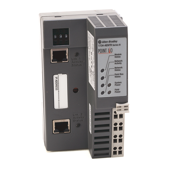
Wire the ArmorPOINT I/O Adapter ATTENTION You must use series C POINT I/O modules with the adapter. Series A or B POINT I/O modules will not work with the adapter. Identify Adapter Use the figure to identify the external features of your I/O adapters... -
Page 18: Mount The I/O Adapter
Mount a 1734-FPD module in the slot next to the I/O adapter when applying field power. You can also use the 24V DC to power the adapter to supply field power, where no FPD is necessary. Refer to Point I/O Field Potential Distribution Module Installation Instructions, publication 1734-IN059 more information. -
Page 19: Mount The Point I/O Adapter On A Din Rail
Install Your Adapter Mount the POINT I/O Adapter on a DIN Rail Position the I/O adapters vertically above the DIN rail. 1. Make sure that the DIN rail lock is in horizontal position. 2. Press down firmly to install the adapter on a DIN rail, noting that the locking mechanism locks the adapter to the DIN rail. - Page 20 Install Your Adapter Refer to the drilling dimensions illustration for the ArmorPOINT I/O adapter with I/O bases to guide you in mounting the adapter and I/O bases. Drilling Dimensions 46.25mm 51.90mm 20.10mm 51.90mm 20.10mm 51.90mm (1.82in) (2.04in) (0.79in) (2.04in) (0.79in) (2.04in) 56.00mm (2.20in)
-
Page 21: Install The Point I/O Adapter Module
Install Your Adapter Install the POINT I/O To install the adapter on the DIN rail prior to installing other base units: Adapter Module ATTENTION Allow 25.4 mm (1 in.) of space between adjacent equipment for adequate ventilation. 1. Position the adapter vertically above the DIN rail. -
Page 22: Wire The Point I/O Adapter
Install Your Adapter Wire the POINT I/O Adapter Refer to the following illustration to wire the adapter. Chas Chas 12/24V DC This DC supply connects V DC to the internal power bus. NC = No Connection Chas Gnd = Chassis Ground... - Page 23 Install Your Adapter 1738-AENTR EtherNet/IP Connectors M12 Female In Connector (view into connector) Pin 1 - Tx + Pin 2 - Rx + Pin 3 - Tx - Pin 4 - Rx - 43765 1738-AENTR Auxiliary Power Connector M18 Male In Connector (view into connector) Pin 1 - User power + Pin 2 - Adapter power +...
- Page 24 Install Your Adapter Notes: Publication 1734-UM014A-EN-P - November 2010...
-
Page 25: Overview
Save the Relation List Use DHCP Software to Configure Your Adapter ATTENTION You must use series C POINT I/O modules with the adapter. Series A or B POINT I/O modules will not work with the adapter. Publication 1734-UM014A-EN-P - November 2010... -
Page 26: Configuration Requirements
Configure the Adapter for Your EtherNet/IP Network Configuration Before you can use your adapter, you must configure its IP address, its subnet mask, and, optionally, a gateway address. You can use the Rockwell BootP Requirements utility, version 2.3 or later, to perform the configuration. You can also use a DHCP server or the network address switches to configure these parameters. -
Page 27: Gateway Address
Configure the Adapter for Your EtherNet/IP Network Gateway Address This section applies to multi-network systems. If you have a single network system, refer to the next section. The Gateway Address is the default address of a network. It provides a single domain name and point of entry to the site. -
Page 28: Subnet Mask
Configure the Adapter for Your EtherNet/IP Network Subnet Mask The subnet mask is used for splitting IP networks into a series of subgroups, or subnets. The mask is a binary pattern that is matched up with the IP address to turn part of the Host ID address field into a field for subnets Take Network 2 (a Class B network) in the previous EXAMPLE example and add another physical network. -
Page 29: Set Thenetwork Address
The adapters ship DHCP-enabled and with the switches set to 999. To change the network address, do the following. Set the Network Address for POINT I/O Adapter • Use the thumbwheel switches located on the adapter. • Use a Dynamic Host Configuration Protocol (DHCP) server, such as Rockwell Automation BootP/DHCP. -
Page 30: Set The Network Address For Armorpoint I/O Adapter
Configure the Adapter for Your EtherNet/IP Network Set the Network Address for ArmorPOINT I/O Adapter • Adjust the switches in front of the module • Use a Dynamic Host Configuration Protocol (DHCP) server such as Rockwell Automation BootP/DHCP • Retrieve the IP address from non-volatile memory The adapter reads the switches first to determine if the switches are set to a valid number. - Page 31 Configure the Adapter for Your EtherNet/IP Network To configure your adapter using the BootP utility, perform the following steps: 1. Run the BootP software. In the BOOTP Request History panel you see the hardware addresses of devices issuing BootP requests. 2.
- Page 32 Configure the Adapter for Your EtherNet/IP Network The New Entry dialog appears with the device’s Ethernet Address (MAC). 3. Enter the IP Address you want to assign to the device and click OK. The device is added to the Relation List, displaying the Ethernet Address (MAC) and corresponding IP Address, Hostname, and Description (if applicable).
-
Page 33: Save The Relation List
Configure the Adapter for Your EtherNet/IP Network Save the Relation List You can save the Relation List for later use. To save the Relation List, perform the following steps: 1. Select Save As... from the File menu. The Save As dialog appears. 2. -
Page 34: Use Dhcp Software To Configure Your Adapter
Configure the Adapter for Your EtherNet/IP Network Use DHCP Software to DHCP (Dynamic Host Configuration Protocol) software automatically assigns IP addresses to client stations logging onto a TCP/IP network. Configure Your Adapter DHCP is based on BootP and maintains some backward compatibility. The main difference is that BootP was designed for manual configuration, while DHCP allows for dynamic allocation of network addresses and configurations to newly attached devices. -
Page 35: Overview
The modules presented in this chapter use RSLogix 5000 software, revision 11. ATTENTION You must use series C POINT I/O modules with the adapter. Series A or B POINT I/O modules will not work with adapter. Topic Page Set Up the Hardware... - Page 36 Configure the Adapter for Direct Connection in RSLogix 5000 Software To work along with this example, set up your system as shown in the figure. 1734-AENTR 10.88.70.2 POINT I/O Slot 0 1 2 3 Link 1 Activity/ Status Local Data...
-
Page 37: Create The Example Application
Configure the Adapter for Direct Connection in RSLogix 5000 Software Create the Example Perform the following steps to create the example application: Application 1. Start RSLogix 5000 Enterprise Series software to open the RSLogix 5000 main dialog. 2. From the File menu, select New. 3. -
Page 38: Configure The I/O
6. Click OK. Configure the I/O You now add the POINT I/O modules to the controller’s I/O configuration performing these procedures: • Add the local 1756-ENBT module to the I/O configuration. • Add the 1734-AENTR adapter as a child of the 1756-ENBT module on the Ethernet network. - Page 39 Configure the Adapter for Direct Connection in RSLogix 5000 Software The Select Module dialog opens. 3. Expand the Communications tree as in the following dialog. 4. Select the 1756-ENBT EtherNet/IP Bridge and click OK. The Select Major Revision dialog opens. 5.
- Page 40 Configure the Adapter for Direct Connection in RSLogix 5000 Software The New Module dialog opens. 6. Enter values for Name, IP Address, Slot, Electronic Keying, and Revision, noting that we used the following values: Name Local_ENBT IP Address 10.88.70.4 Slot Electronic Keying Compatible Keying Revision...
-
Page 41: Add The Point I/O Adapter To The I/O Configuration
Configure the Adapter for Direct Connection in RSLogix 5000 Software Add the POINT I/O Adapter Next, you must add the adapter as a child of the local 1756-ENBT module. to the I/O Configuration 1. In the Project dialog, right-click the local 1756-ENBT module under the I/O Configuration folder, and select New Module from the dialog. - Page 42 Configure the Adapter for Direct Connection in RSLogix 5000 Software 3. Select your adapter from the list, and click OK, noting that we entered these values on the General Tab of the New Module dialog. Name POINT_IO_Adapter IP Address 10.88.70.2 The Slot field appears grey because the slot is automatically 0 for IMPORTANT the 1734-AENTR adapter.
- Page 43 6. Choose None as Connection, because we are only making direct connections, then click OK. There is no need to have a rack-optimized connection if all I/O connections to the POINT I/O modules are directly connected. A dialog box opens.
-
Page 44: Add The Point I/O Modules To The I/O Configuration
Configure the Adapter for Direct Connection in RSLogix 5000 Software Add the POINT I/O Modules to the I/O Configuration You now add POINT I/O modules to the I/O Configuration List under the adapter. In this example, you add a 1734-OW2 relay output and a 1734-OV4E sink output modules with standard configurations. - Page 45 Configure the Adapter for Direct Connection in RSLogix 5000 Software 3. Select the 1734-OW2 relay output module from the list and click OK. The New Module dialog opens. 4. Enter values for Name and Slot, noting that we used the following values.
- Page 46 Configure the Adapter for Direct Connection in RSLogix 5000 Software 7. Click OK to save the configuration. The relay output module appears under Ethernet. Add the Digital Output Module 1. Right-click the name of the I/O adapter and select New Module. The Select Module dialog opens.
- Page 47 Configure the Adapter for Direct Connection in RSLogix 5000 Software 2. Select the 1734-OV4E digital output module from the list 3. Click OK. The New Module dialog opens. Enter values for Name and Slot, noting we used the following. Name POINT_Digital_Output Slot 4.
-
Page 48: Edit The Controller Tags
Configure the Adapter for Direct Connection in RSLogix 5000 Software The I/O Configuration in the Project dialog should look similar to the following Edit the Controller Tags When you add modules to the I/O configuration the system creates tags for those modules to use in the application program. - Page 49 Configure the Adapter for Direct Connection in RSLogix 5000 Software The Controller Tags dialog opens. You see the tags created for the 1734-AENTR adapter and its digital I/O modules. Tags created by the system Enter the new tag here 2. Click the Edit Tags tab at the bottom of the Controller Tags dialog. 3.
-
Page 50: Create The Ladder Program
Configure the Adapter for Direct Connection in RSLogix 5000 Software Create the Ladder Program Create the example ladder program to test the I/O. 1. Under the Main Program folder, double-click Main Routine. 2. Enter the following ladder program using the tags previously created. 3. -
Page 51: Verify The Module Chassis Size
Configure the Adapter for Direct Connection in RSLogix 5000 Software 3. Choose Set Project Path. 4. Choose Download. The Download dialog opens with a reminder of the following. • The controller is in Remote Run mode. • The mode changes to Remote Program prior to download. 5. - Page 52 Configure the Adapter for Direct Connection in RSLogix 5000 Software 1. Verify that the RSLogix 5000 software is online. 2. In the Project dialog, right-click the 1734-AENTR adapter under I/O Configuration. 3. Select Properties. 4. Click the Connection tab. The Module Fault error code displays. 5.
-
Page 53: Configure The Adapter With Fixed Ip Address
Configure the Adapter for Direct Connection in RSLogix 5000 Software 7. Read and acknowledge the warning dialog. 8. Click OK to continue. Notice the chassis size stored in the module has been changed to 3. At this point, your POINTBus status LED should be solid green. All the yellow triangles in your I/O configuration should be gone. -
Page 54: Recover From An Overloaded Adapter
Configure the Adapter for Direct Connection in RSLogix 5000 Software 2. In the Module Properties dialog, click the Port Configuration tab. 3. Unselect the Enable DHCP box. 4. Click the Set button. 5. Read and acknowledge the warning. 6. Click OK. 7. - Page 55 Configure the Adapter for Direct Connection in RSLogix 5000 Software The condition where the I/O adapters cannot support the connection due to a limit of the bandwidth of the microprocessor is shown on the Connection tab of the Module Properties dialog. If you encounter this condition, the only action you can take is to alter the existing connections to reduce the amount of microprocessor bandwidth consumed.
- Page 56 Configure the Adapter for Direct Connection in RSLogix 5000 Software Notes: Publication 1734-UM014A-EN-P - November 2010...
-
Page 57: Overview
Download the Program to the Controller Verify the Module Chassis Size Access Module Data ATTENTION You must use series C POINT I/O modules with the adapter. Series A or B POINT I/O modules will not work with the adapter. Publication 1734-UM014A-EN-P - November 2010... -
Page 58: Set Up The Hardware
1734-AENTR adapter on a DIN rail in slot 0, with a 1734-OW2/C relay output module in slot 1, a 1734-OV4E/C sink output module in slot 3, and two other POINT I/O modules which will not be controlled by this Logix controller in slots 2 and 4. -
Page 59: Create The Example Application
Configure the Adapter for Direct Connection and Rack Optimization in RSLogix 5000 Software Create the Example Perform the following steps to create the example application: Application 1. Start the RSLogix 5000 Enterprise Series software. The RSLogix 5000 software main dialog opens. 2. -
Page 60: Configure The I/O Modules
Configure the Adapter for Direct Connection and Rack Optimization in RSLogix 5000 Software RSLogix 5000 software, revision 11 and later includes enable redundancy. This example does not use redundancy. 8. Click OK. Configure the I/O Modules You now add the I/O modules to the controller I/O configuration. To do this, first add the local 1756-ENBT module to the I/O configuration. - Page 61 Configure the Adapter for Direct Connection and Rack Optimization in RSLogix 5000 Software 3. Expand the Communications tree, as in the following dialog and select the 1756-ENBT EtherNet/IP Bridge. 4. Click OK. The Select Major Revision dialog opens. 5. Select the value for Major Revision and click OK. The Module Properties dialog opens.
-
Page 62: Add The I/O Adapter To The I/O Configuration
Configure the Adapter for Direct Connection and Rack Optimization in RSLogix 5000 Software 6. Enter values for Name, IP Address, Slot, Electronic Keying, and Revision, noting we used the following values: Name Local_ENB IP Address 10.88.70.4 Slot Electronic Keying Compatible Module Revision 7. - Page 63 Configure the Adapter for Direct Connection and Rack Optimization in RSLogix 5000 Software 2. Expand the Communications tree and select the 1734-AENTR Ethernet Adapter from the list. 3. Click OK. The New Module dialog opens. 4. Enter values for Name and IP Address, noting we used the following values.
- Page 64 Configure the Adapter for Direct Connection and Rack Optimization in RSLogix 5000 Software 5. On the General tab, click Change... The Module Definition dialog opens. 6. Enter values for Connection, Chassis Size, Electronic Keying, and Revision. Connection Rack Optimization Chassis Size Electronic Keying Compatible Module Revision...
- Page 65 Configure the Adapter for Direct Connection and Rack Optimization in RSLogix 5000 Software The New Module properties dialog opens. 9. Verify that the requested packet interval (RPI) is appropriate for your system. You use this value for the rack-optimized connection to the I/O modules.
-
Page 66: Add The Point I/O Module And Configure For Rack-Optimized Connection
Configure the Adapter for Direct Connection and Rack Optimization in RSLogix 5000 Software Add the POINT I/O Module and Configure for Rack-optimized Connection 1. Right-click the POINT I/O Chassis in the I/O Configuration folder and select New Module … The Select Module dialog opens. - Page 67 Configure the Adapter for Direct Connection and Rack Optimization in RSLogix 5000 Software The New Module dialog opens. 4. Click Change... and then enter values for Name and Slot, noting we used the following values. Name POINT_Relay_Output Slot 5. Note that the requested packet interval (RPI) is the same as was chosen by the adapter.
-
Page 68: Direct Connection
I/O Configuration folder. Add the POINT I/O Module and Configure For Direct Connection 1. Right-click the POINT I/O Chassis in the I/O Configuration folder, and select New Module If you exceed the adapter chassis size trying to add more modules... - Page 69 Configure the Adapter for Direct Connection and Rack Optimization in RSLogix 5000 Software 2. Expand the Digital tree. 3. Choose the 1734-OV4E/C module and click OK. The New Module dialog opens. 4. From the New Module dialog, complete the following: –...
-
Page 70: Download The Program To The Controller
Configure the Adapter for Direct Connection and Rack Optimization in RSLogix 5000 Software 5. For Connection, select Data. This configures the controller to make a Direct I/O Connection to the module. 6. Click OK. 7. From the New Module dialog, click the Connection tab. The New Module dialog opens. - Page 71 Configure the Adapter for Direct Connection and Rack Optimization in RSLogix 5000 Software 2. From the Who Active dialog, navigate to select the slot where the controller is located in the chassis. 3. Click Set Project Path. 4. Click Download. The Download dialog opens.
-
Page 72: Verify The Module Chassis Size
Configure the Adapter for Direct Connection and Rack Optimization in RSLogix 5000 Software Verify the Module You have now built the I/O tree and the RSLogix 5000 software uses the chassis size from the General tab of the adapter for the rack-optimized I/O Chassis Size connection. - Page 73 Configure the Adapter for Direct Connection and Rack Optimization in RSLogix 5000 Software 6. Click Set Chassis Size in Module. 7. Read and acknowledge the warning dialog. 8. Click OK to continue. Publication 1734-UM014A-EN-P - November 2010...
-
Page 74: Access Module Data
• POINT_IO_Adapter — the name you gave to your EtherNet adapter • # — slot number of POINT I/O module • C — configuration, I = input, O = output Use the controller tags in your ladder program to read input data or write output data. - Page 75 POINT I/O modules that use a rack-optimized connection. – Bit 0 is reserved for the adapter and always reports a value of 1. – Each of the other bits (1 to 63) correspond to a POINT I/O module that you install in the POINT I/O backplane.
- Page 76 Configure the Adapter for Direct Connection and Rack Optimization in RSLogix 5000 Software Notes: Publication 1734-UM014A-EN-P - November 2010...
-
Page 77: Overview
Status Indicators for ArmorPOINT I/O Adapter Interpret the Status Read this chapter to learn about what the LED status indicators mean for the POINT I/O and ArmorPOINT I/O EtherNet/IP adapters. Indicators Status Indicators for POINT I/O Adapter The following describes the status indicators on the 1734-AENTR. - Page 78 Interpret the Status Indicators Status Indicators for 1734-AENTR Adapter Status Description Module status No power applied to device Solid green Device operating normally Flashing red/green Module self-test Flashing red Recoverable fault. Complete firmware update, verify address switches. Solid red Unrecoverable fault, may require device replacement. Network status Device is not online - Device has not completed Dup_MAC_ID test.
- Page 79 Interpret the Status Indicators Status Indicators for 1734-AENTR Adapter Status Description POINTBus status Device is not online. Device has not completed Dup_MAC_ID test. Device not powered - check module status indicator. Flashing green Device is online but has no connections in the established state. Firmware (NVS) update in progress.
-
Page 80: Status Indicators For Armorpoint I/O Adapter
Interpret the Status Indicators Status Indicators for ArmorPOINT I/O Adapter The following describes the status indicators on the 1738-AENTR. This module has the following indicators: • Adapter, Network, and POINTBus status indicators for EtherNet/IP • Adapter and System power indicators •... - Page 81 Interpret the Status Indicators Status Indicators for 1738-AENTR Adapter Status Description Network activity No link established with Port 1 or Port 2. Green Link established with Port 1 and/or Port 2 at 100 Mbps. Link established with Port 1 and Port 2. One port at 100 Mbps and one port at 10 Mbps Flashing green Transmit or receive activity present on Port 1 and/or Port 2 at 100 Mbps.
- Page 82 Interpret the Status Indicators Notes: Publication 1734-UM014A-EN-P - November 2010...
-
Page 83: Specifications
Appendix EtherNet/IP I/O Adapter Specifications Specifications Following are specifications for the ArmorPOINT I/O and POINT I/O modules General Specifications – POINT I/O and ArmorPOINT I/O 2 Port EtherNet/IP Adapters 1734-AENTR, 1738-AENTR Specification Description Module location Starter module - left side of the 1734 system... - Page 84 EtherNet/IP I/O Adapter Specifications Specifications – POINT I/O 2 Port EtherNet/IP Adapter 1734-AENTR Specification Description Expansion I/O •Maximum of 63 modules capacity •Maximum of 5 Rack Optimized connections (for digital modules only) •Maximum of 20 Direct connections •POINT I/O 1734-AENTR backplane current output= 0.8 A maximum.
- Page 85 EtherNet/IP I/O Adapter Specifications Specifications – POINT I/O 2 Port EtherNet/IP Adapter 1734-AENTR Specification Description Expansion I/O 1734-OE4C 75 mA capacity 1734-IA4 75 mA 1734-IM4 75 mA 1734-OA4 75 mA 1734-IR2E 75 mA 1734-8CFG 100 mA Ethernet 10/100 Mbps, half or full-duplex...
- Page 86 EtherNet/IP I/O Adapter Specifications Specifications – AmorPOINT I/O 2 Port EtherNet/IP Adapter 1738-AENTR Specification Description Expansion I/O •Maximum of 63 modules capacity •Maximum of 5 Rack Optimized connections (for digital modules only) •Maximum of 20 Direct connections •1738-AENTR backplane current output =0.8 A. The actual number of modules varies.
- Page 87 EtherNet/IP I/O Adapter Specifications Environmental Specifications Specification Description Temperature, IEC 60068-2-1 (Test Ad, Operating Cold), operating IEC 60068-2-2 (Test Bd, Operating Dry Heat), IEC 60068-2-14 (Test Nb, Operating Thermal Shock): -20…55 °C (-4…131 °F) – 1734-AENTR -20…60 °C (-4…140 °F) – 1738-AENTR Temperature, storage IEC 60068-2-1 (Test Ab, Unpackaged Nonoperating Cold), IEC 60068-2-2 (Test Bb, Unpackaged Nonoperating Dry Heat), IEC 60068-2-14 (Test Na, Unpackaged Nonoperating Thermal...
- Page 88 EtherNet/IP I/O Adapter Specifications Certifications Certifications (when Value product is marked) 1734-AENTR only c-UL-us UL Listed Industrial Control Equipment, certified for US and Canada. See UL File E65584 UL Listed for Class I, Division 2 Group A,B,C,D Hazardous Locations, certified for U.S. and Canada. See UL File E194810. European Union 2004/108/EC EMC Directive, compliant with: EN 61326-1;...
-
Page 89: Overview
Appendix Adapter Web Dialogs Overview The Web dialog of the I/O adapter offers extensive internal and network diagnostics. To view the Web dialogs, enter the IP address of the I/O adapters into your browser For Information About Page Work with the Home Page Work with the Diagnostics Pages Use the Diagnostic Overview Page Use the Network Settings Page... - Page 90 Adapter Web Dialogs To display and work with the adapter diagnostics home page, follow these procedures. Make sure that your PC Internet LAN setting and your TCP/IP IMPORTANT settings are configured to access the subnet on which your adapter communicates. 1.
-
Page 91: Work With The Diagnostics
Adapter Web Dialogs 3. From the Home page, complete one of these, as desired. • Click one of the following to access www.ab.com. – Allen-Bradley logo at the top of the page – Visit for additional information statement under Resources ab.com... -
Page 92: Use The Diagnostic Overview Page
Adapter Web Dialogs Use the Diagnostic Overview Page To use the Diagnostic Overview page for general diagnostics information, follow this procedure. 1. Click Diagnostic Overview from the tab at the top of the page or panel on the left. The Diagnostic Overview page opens. 2. -
Page 93: Use The Network Settings Page
Adapter Web Dialogs – Max Msg Connections Observed – Current CIP I/O Connections – CIP I/O Connection Limit – Max I/O Connections Observed – Conn Opens – Open Errors – Conn Closes – Close Errors – Conn Timeout – Status •... -
Page 94: Use The Ethernet Statistics Page
Adapter Web Dialogs • Network Interface – Ethernet Address (MAC) – IP Address – Subnet Mask – Default Gateway – Primary Name Server – Secondary Name Server – Default Domain Name – Host Name – Name Resolution • Ethernet Interface Configuration –... - Page 95 Adapter Web Dialogs The Ethernet Statistics page opens. 2. From the Ethernet Statistics page, view the following: • Ethernet Link – Media Speed, Half or Full Duplex, Autonegotiate Status • Interface Counters – In Octets, In UCast Packets, In NUcast Packets, In Discards, In Errors, In Unknown Protos, Out Octets, Out Ucast Packets, Out NUcast Packets, Out Discards, Out Errors...
-
Page 96: Use The I/O Connections Page
Adapter Web Dialogs – Carrier Sense Errors – Frame Too Long – MAC Receive Errors Use the I/O Connections Page To use the I/O Connections page for CIP I/O (Class 1) connection information, follow this procedure. 1. Click I/O Connections from the tab at the top of the page or panel on the left. -
Page 97: Use The Diagnostic Messaging Page
Adapter Web Dialogs • Lost/Slot that shows the number of lost packets and the slot number for the connection, with a slot value of 0 indicating that this is a rack-optimized connection • Size of data in bytes Use the Diagnostic Messaging Page To use the Diagnostic Messaging page to execute explicit, unconnected message services, use this procedure. -
Page 98: Work With The Configuration
Adapter Web Dialogs 3. From the Diagnostic Messaging page, click Submit to see values similar to that shown. Work with the To work with the Configuration pages, follow these procedures. Configuration Pages The values on these pages are in non-volatile memory. Changes to IMPORTANT these parameters do not take effect until you reset or cycle power through the I/O adapters. -
Page 99: Use The Identity Page
Adapter Web Dialogs 1. From the Home page, click Configuration or Expand to see the Configuration options, if needed. 2. From the Configuration page, click one of the following: • Identity • Network • Services A login dialog opens as shown. The dialog may vary in appearance depending on your operating system and browser. -
Page 100: Use The Network Configuration Page
Adapter Web Dialogs 1. Click Identity from the tab at the top of the page or panel on the left. The Identity page opens 2. From the Identity page, complete entries for the following, noting that the description and location help you identify where modules are in the facility: •... - Page 101 Adapter Web Dialogs 1. Click Network from the tab at the top of the page or panel on the left. The Network Configuration page opens. 2. From the Network Configuration page, complete these entries, noting that values for Network Interface are disabled when DHCP is Dynamic DHCP and port speed and duplex mode are disabled when Autonegotiate Speed and Duplex is selected.
-
Page 102: Use The Services Page
Adapter Web Dialogs 3. From the Network Configuration page, click Apply Changes to save the modified values. Use the Services Page To use the Services page to change the password for the Configuration web page or disable the web server, complete these procedures. 1. - Page 103 Adapter Web Dialogs To work with the Browse Chassis page, follow these procedures. 1. From the Home page, click Browse Chassis Check Increase timeout to increase time of the browse query and the time the modules get to respond to the query. This is useful when browsing a busy system.
- Page 104 Adapter Web Dialogs 4. Click Start to run the query. A Browser Chassis page opens. Note that module hyperlinks are inactive before the query completes or is cancelled. Before the query completes, this note about the disabled module hyperlinks appears. Before the query completes, If there is no response to the query, module hyperlinks are inactive.
- Page 105 Adapter Web Dialogs • Product Type • Product Code • Module Revision • Serial Number • Status Publication 1734-UM014A-EN-P - November 2010...
- Page 106 Adapter Web Dialogs Notes: Publication 1734-UM014A-EN-P - November 2010...
-
Page 107: Overview
Appendix Configure the RSLinx Ethernet Communication Driver Overview To communicate with your adapter over your network, you must configure the RSLinx Ethernet Communication Driver (AB_ETH) or the EtherNet/IP driver (AB-ETHIP). You can configure the AB_ETH driver with the IP addresses of all the Ethernet devices on your system. You need one of these drivers to download the example application programs in this manual. - Page 108 Configure the RSLinx Ethernet Communication Driver 2. From the Communications menu, select Configure Drivers. 3. Select Ethernet Devices from the list and click Add/New... 4. Select the default driver name (for example, AB_ETH-1) or type in a name and click OK. The Configure driver dialog opens.
-
Page 109: Configure The Ab_Eth/Ip Driver
Configure the RSLinx Ethernet Communication Driver 5. Click Add New and enter the IP address or Host Name of your Ethernet device (for example, 10.88.70.4, Pump1). 6. Repeat step 6 for each additional Ethernet device you need to access. 7. After entering the IP addresses, click Apply. 8. -
Page 110: Publication 1734-Um014A-En-P - November
Configure the RSLinx Ethernet Communication Driver 2. From the Communications menu, select Configure Drivers. 3. Select EtherNet/IP Devices from the list and click Add/New... Publication 1734-UM014A-EN-P - November 2010... - Page 111 Configure the RSLinx Ethernet Communication Driver The Configure Driver dialog box opens. Make sure the Browse Local Subnet button is selected. The RSLinx software browses your local subnet and automatically reads the IP address. 4. Click OK. The AB-ETHIP driver is now configured and appears in the configured drivers window.
- Page 112 Configure the RSLinx Ethernet Communication Driver Notes: Publication 1734-UM014A-EN-P - November 2010...
- Page 113 Index Numerics 1734/1738 daisy chain 2 data overview 1 messaging 5 Default Gateway 86 device adapter consuming 5 AENTR 46 producing 5 diagnostics 81 DHCP 21 I/O 5 (Dynamic Host Configuration Protocol) 26 mounted 27 enabled 21 address server 17 fixed IP 45 Diagnostic Gateway 17...
- Page 114 Index IP Address 86 IP address 17 Gateway fixed 45 default 86 IP network 18 Gateway address 17 splitting 20 Home page 81 ladder logic Host ID 20 program 66 Host Name 86 ladder program host name 91 example 42 Media Counters 87 adapter 5 messaging...
- Page 115 Index status indicators 69 subgroup 20 power up system for the first time 4 subnet 20 primary tasks 5 Subnet Mask 86 protocol subnet mask 17 message-based 5 publications related i TCP 21 TCP/IP network 26 Transport Control Protocol 21 rack optimized connection 7 rack-optimized 7 rate of change 46...
- Page 116 Index Notes: Publication 1734-UM014A-EN-P - November 2010...
- Page 118 Rockwell Automation Support Rockwell Automation provides technical information on the Web to assist you in using its products. At http://www.rockwellautomation.com/support/, you can find technical manuals, a knowledge base of FAQs, technical and application notes, sample code and links to software service packs, and a MySupport feature that you can customize to make the best use of these tools.