
Related Manuals for Allen-Bradley Micro830


Summary of Contents for Allen-Bradley Micro830
- Page 1 User Manual Micro830 and Micro850 Programmable Controllers Catalog Numbers Bulletin 2080-LC30 and 2080-LC50...
- Page 2 Identifies information that is critical for successful application and understanding of the product. IMPORTANT Allen-Bradley, Rockwell Software, Rockwell Automation, Micro800, Micro830, Micro850, Connected Components Workbench, and TechConnect are trademarks of Rockwell Automation, Inc. Trademarks not belonging to Rockwell Automation are property of their respective companies.
-
Page 3: Preface
GENERIC and CIP Symbolic Messaging. Micro800 Programmable Controller External AC Information on mounting and wiring the optional Power Supply Installation Instructions external power supply. 2080-IN001 Micro830 Programmable Controllers Installation Information on mounting and wiring the Instructions 2080-IN002 Micro830 10-point Controllers. Micro830 Programmable Controllers Installation... - Page 4 Preface Resource Description Micro830 Programmable Controllers Installation Information on mounting and wiring the Instructions 2080-IN005 Micro830 48-point Controllers. Micro850 Programmable Controllers Installation Information on mounting and wiring the Instructions 2080-IN007 Micro850 24-point Controllers Micro850 Programmable Controllers Installation Information on mounting and wiring the...
- Page 5 National Electrical Code - Published by the An article on wire sizes and types for grounding National Fire Protection Association of Boston, electrical equipment. Allen-Bradley Industrial Automation Glossary A glossary of industrial automation terms and AG-7.1 abbreviations. You can view or download publications at http://www.rockwellautomation.com/...
- Page 6 Preface Notes: Rockwell Automation Publication 2080-UM002G-EN-E - March 2015...
-
Page 7: Table Of Contents
Micro830 Controllers ........ - Page 8 Table of Contents Chapter 3 Install Your Controller Controller Mounting Dimensions ....... . . 27 Mounting Dimensions .
- Page 9 Chapter 1 Chapter 6 Program Execution in Micro800 Overview of Program Execution ........61 Execution Rules .
- Page 10 Table of Contents Chapter 8 Use the High-Speed Counter High-Speed Counter Overview ........119 Programmable Limit Switch Overview .
- Page 11 Micro830 Controllers ........
- Page 12 Flash Upgrade Your Micro800 Firmware ......189 Establish Communications Between RSLinx and a Micro830/Micro850 Controller through USB ......... 194 Configure Controller Password.
- Page 13 System Loading Calculate Total Power for Your Micro830/Micro850 Controller 263 ............264...
- Page 14 Table of Contents Notes: Rockwell Automation Publication 2080-UM002G-EN-E - March 2015...
-
Page 15: Hardware Overview
Chapter Hardware Overview This chapter provides an overview of the Micro830 and Micro850 hardware features. It has the following topics: Topic Page Hardware Features Micro830 Controllers Micro850 Controllers Programming Cables Embedded Serial Port Cables Embedded Ethernet Support Hardware Features Micro830 and Micro850 controllers are economical brick style controllers with embedded inputs and outputs. -
Page 16: Micro830 Controllers
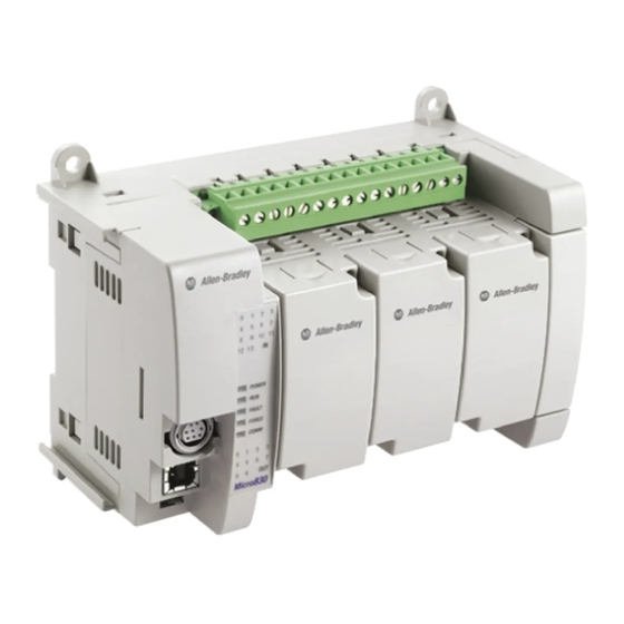
Micro800 power supply. Troubleshooting on page 243 for descriptions of status indicator operation for troubleshooting purposes. Micro830 Controllers Micro830 10/16-point controllers and status indicators Status indicator Controller 45031 45030 Micro830 24-point controllers and status indicators... - Page 17 Hardware Overview Chapter 1 Micro830 48-point controllers and status indicators Controller Status indicator 45037 45036 Controller Description Description Description Status indicators Mounting screw hole / mounting foot Optional power supply slot DIN rail mounting latch Plug-in latch Mode switch Plug-in screw hole...
-
Page 18: Micro850 Controllers
Chapter 1 Hardware Overview Micro850 Controllers Micro850 24-point controllers and status indicators Status indicators 45910 45909 Controller Description Description Description Status indicators Expansion I/O slot cover Optional power supply slot DIN rail mounting latch Plug-in latch Mode switch Plug-in screw hole Type B connector USB port 40 pin high speed plug-in connector RS232/RS485 non-isolated combo serial port... - Page 19 Power status Output status Run status (1) For detailed descriptions of these LED status indicators, see Troubleshooting on page 243. Micro830 Controllers – Number and Type of Inputs/Outputs Catalog Number Inputs Outputs PTO Support HSC Support 110V AC 24V DC/V AC Relay...
-
Page 20: Programming Cables
Chapter 1 Hardware Overview Micro830 Controllers – Number and Type of Inputs/Outputs Catalog Number Inputs Outputs PTO Support HSC Support 110V AC 24V DC/V AC Relay 24V Sink 24V Source 2080-LC30-16QVB 2080-LC30-24QBB 2080-LC30-24QVB 2080-LC30-24QWB 2080-LC30-48AWB 2080-LC30-48QBB 2080-LC30-48QVB 2080-LC30-48QWB Micro850 Controllers – Number and Types of Inputs and Outputs... -
Page 21: Embedded Serial Port Cables
Hardware Overview Chapter 1 Embedded Serial Port Cables Embedded serial port cables for communication are listed here. All embedded serial port cables must be 3 meters in length, or shorter. Embedded Serial Port Cable Selection Chart Connectors Length Cat. No. Connectors Length Cat. - Page 22 Chapter 1 Hardware Overview Notes: Rockwell Automation Publication 2080-UM002G-EN-E - March 2015...
-
Page 23: About Your Controller
It requires the Connected Components Workbench Developer Edition Release 8 software to use this feature. Micro820/Micro830/Micro850 controller firmware revision 8.0 or higher IMPORTANT is also required to use Run Mode Change. Rockwell Automation Publication 2080-UM002G-EN-E - March 2015... - Page 24 Chapter 2 About Your Controller RMC is useful when the user is developing a project by incrementally adding small changes to the logic and immediately wants to see the effects of the changes on the machine. With RMC, since the controller stays in remote run mode, the controller logic and machine actuators will not have to constantly reinitialize, which can occur if the controller is switched to remote program mode (for example, first scan bit is checked in program logic to clear outputs).
-
Page 25: Uncommitted Changes
About Your Controller Chapter 2 When a Test Logic is performed, or undoing changes after the Test Logic IMPORTANT is completed, any active communication instructions will be aborted while the changes are downloaded to the controller. Uncommitted Changes Uncommitted changes are changes made in RMC that have not been accepted or undone after a Test Logic Change has been performed. - Page 26 Chapter 2 About Your Controller RMC Memory Usage Example Controller Memory RMC Memory (for User Program + Data) (Default size = 2KB) 1st change and 2nd change and 3rd change and Test Logic Test Logic Test Logic (Add logic) (Remove logic) (Add logic) Free memory Free RMC memory...
-
Page 27: Limitations Of Rmc
About Your Controller Chapter 2 Insufficient Controller Memory Example Controller Memory RMC Memory (for User Program + Data) (Default size = 2KB) Free RMC memory Error will occur due to insufficient controller memory remaining Used memory Limitations of RMC Take note of the following limitations when using the Run Mode Change (RMC) feature: •... -
Page 28: Agency Certifications
EN 61131-2 Programmable Controllers, Part 2 - Equipment Requirements and Tests. For specific information required by EN 61131-2, see the appropriate sections in this publication, as well as the following Allen-Bradley publications: • Industrial Automation Wiring and Grounding Guidelines for Noise Immunity, publication 1770-4.1. -
Page 29: Installation Considerations
About Your Controller Chapter 2 Installation Considerations Most applications require installation in an industrial enclosure (Pollution Degree 2 ) to reduce the effects of electrical interference (Over Voltage Category II ) and environmental exposure. Locate your controller as far as possible from power lines, load lines, and other sources of electrical noise such as hard-contact switches, relays, and AC motor drives. -
Page 30: Environment And Enclosure
Chapter 2 About Your Controller ATTENTION: To comply with the CE Low Voltage Directive (LVD), this equipment must be powered from a source compliant with the following: Safety Extra Low Voltage (SELV) or Protected Extra Low Voltage (PELV). ATTENTION: To comply with UL restrictions, this equipment must be powered from a Class 2 source. ATTENTION: Be careful when stripping wires. - Page 31 About Your Controller Chapter 2 This equipment is sensitive to electrostatic discharge, which can cause internal damage and affect normal operation. Follow these guidelines when you handle this equipment: • Touch a grounded object to discharge potential static. • Wear an approved grounding wriststrap. •...
-
Page 32: Safety Considerations
Chapter 2 About Your Controller Safety Considerations Safety considerations are an important element of proper system installation. Actively thinking about the safety of yourself and others, as well as the condition of your equipment, is of primary importance. We recommend reviewing the following safety considerations. -
Page 33: Safety Circuits
About Your Controller Chapter 2 Safety Circuits WARNING: Explosion Hazard Do not connect or disconnect connectors while circuit is live. Circuits installed on the machine for safety reasons, like overtravel limit switches, stop push buttons, and interlocks, should always be hard-wired directly to the master control relay. -
Page 34: Power Considerations
Chapter 2 About Your Controller Power Considerations The following explains power considerations for the micro controllers. Isolation Transformers You may want to use an isolation transformer in the AC line to the controller. This type of transformer provides isolation from your power distribution system to reduce the electrical noise that enters the controller and is often used as a step- down transformer to reduce line voltage. -
Page 35: Input States On Power Down
About Your Controller Chapter 2 Input States on Power Down The power supply hold-up time as described above is generally longer than the turn-on and turn-off times of the inputs. Because of this, the input state change from “On” to “Off ” that occurs when power is removed may be recorded by the processor before the power supply shuts down the system. -
Page 36: Master Control Relay
Chapter 2 About Your Controller Master Control Relay A hard-wired master control relay (MCR) provides a reliable means for emergency machine shutdown. Since the master control relay allows the placement of several emergency-stop switches in different locations, its installation is important from a safety standpoint. Overtravel limit switches or mushroom-head push buttons are wired in series so that when any of them opens, the master control relay is de-energized. -
Page 37: Using Emergency-Stop Switches
About Your Controller Chapter 2 Using Emergency-Stop Switches When using emergency-stop switches, adhere to the following points: • Do not program emergency-stop switches in the controller program. Any emergency-stop switch should turn off all machine power by turning off the master control relay. •... -
Page 38: Schematic - Using Iec Symbols
Chapter 2 About Your Controller Schematic – Using IEC Symbols 230V AC Disconnect Fuse 230V AC circuits Isolation Operation of either of these contacts will transformer remove power from the external I/O Master Control Relay (MCR) circuits, stopping machine motion. 115V AC Cat. -
Page 39: Schematic - Using Ansi/Csa Symbols)
About Your Controller Chapter 2 Schematic – Using ANSI/CSA Symbols) 230V AC Disconnect Fuse 230V AC output circuits Isolation Operation of either of these contacts will Transformer remove power from the external I/O Master Control Relay (MCR) circuits, stopping machine motion. 115V AC or Cat. - Page 40 Chapter 2 About Your Controller Notes: Rockwell Automation Publication 2080-UM002G-EN-E - March 2015...
-
Page 41: Install Your Controller
Mounting Dimensions DIN Rail Mounting Panel Mounting Controller Mounting Mounting Dimensions Dimensions Mounting dimensions do not include mounting feet or DIN rail latches. Micro830 10- and 16-Point Controllers 2080-LC30-10QWB, 2080-LC30-10QVB, 2080-LC30-16AWB, 2080-LC30-16QWB, 2080-LC30-16QVB 100 (3.94) 80 (3.15) 90 (3.54) 45032... - Page 42 Chapter 3 Install Your Controller Micro830 24-Point Controllers 2080-LC30-24QWB, 2080-LC30-24QVB, 2080-LC30-24QBB 80 (3.15) 150 (5.91) 90 (3.54) 45018 Measurements in millimeters (inches) Micro830 48-Point Controllers 2080-LC30-48AWB, 2080-LC30-48QWB, 2080-LC30-48QVB, 2080-LC30- 48QBB 210 (8.27) 80 (3.15) 90 (3.54) 45038 Measurements in millimeters (inches)
-
Page 43: Din Rail Mounting
DIN rail. 2. Push the DIN rail latch back into the latched position. Use DIN rail end anchors (Allen-Bradley part number 1492-EAJ35 or 1492-EAHJ35) for vibration or shock environments. To remove your controller from the DIN rail, pry the DIN rail latch downwards until it is in the unlatched position. -
Page 44: Panel Mounting
For instructions on how to install your Micro800 system with expansion IMPORTANT I/O, see the User Manual for Micro800 Expansion I/O Modules, 2080-UM003. Panel Mounting Dimensions Micro830 10- and 16-Point Controllers 2080-LC30-10QWB, 2080-LC30-10QVB, 2080-LC30-16AWB, 2080-LC30- 16QWB, 2080-LC30-16QVB 86 mm (3.39 in.) 45325... - Page 45 Install Your Controller Chapter 3 Micro830 24-Point Controllers 2080-LC30-24QWB, 2080-LC30-24QVB, 2080-LC30-24QBB 131 mm (5.16 in.) 45326 Micro850 24-Point Controllers 2080-LC50-24AWB, 2080-LC50-24QBB, 2080-LC50-24QVB, 2080-LC50-24QWB 131 mm (5.16 in.) 45913 Micro830 48-Point Controllers 2080-LC30-48AWB, 2080-LC30-48QWB, 2080-LC30-48QVB, 2080-LC30-48QBB Rockwell Automation Publication 2080-UM002G-EN-E - March 2015...
- Page 46 Chapter 3 Install Your Controller 108 mm (4.25 in) 108 mm (4.25 in) 100mm (3.9 in) 45917 Rockwell Automation Publication 2080-UM002G-EN-E - March 2015...
-
Page 47: System Assembly
Install Your Controller Chapter 3 System Assembly Micro830 and Micro850 24-point Controllers (Front) 27.8 145.2 44.4 14.4 33.8 110.8 36.6 22.8 Micro830/Micro850 24pt Controller Expansion I/O Slots with Micro800 Power Supply (Applicable to Micro850 only) Measurements in millimeters Single-width (1st slot) - Page 48 27.8 33.8 100.1 110.8 36.6 22.8 Expansion I/O Slots Micro830/Micro850 48pt Controller with Micro800 Power Supply (Applicable to Micro850 only) Single-width (1st slot) Double-width (2nd slot) Measurements in millimeters 2085-ECR (terminator) Micro830 and Micro850 48-point Controllers (Side) Expansion I/O Slots...
-
Page 49: Wire Your Controller
Chapter Wire Your Controller This chapter provides information on the Micro830 and Micro850 controller wiring requirements. It includes the following sections: Topic Page Wiring Requirements and Recommendation Use Surge Suppressors Recommended Surge Suppressors Grounding the Controller Wiring Diagrams Controller I/O Wiring... -
Page 50: Use Surge Suppressors
In addition to labeling, use colored insulation to identify wiring based on signal characteristics. For example, you may use blue for DC wiring and red for AC wiring. Wire Requirements Wire Size Type Micro830/ Solid 0.2 mm (24 AWG) 2.5 mm (12 AWG) rated @ 90 °C (194 °F) - Page 51 Suitable surge suppression methods for inductive AC load devices include a varistor, an RC network, or an Allen-Bradley surge suppressor, all shown below. These components must be appropriately rated to suppress the switching Rockwell Automation Publication 2080-UM002G-EN-E - March 2015...
-
Page 52: Recommended Surge Suppressors
Output device Output device Surge suppressor RC network Varistor Recommended Surge Suppressors Use the Allen-Bradley surge suppressors shown in the following table for use with relays, contactors, and starters. Recommended Surge Suppressors Device Coil Voltage Suppressor Catalog Number Type Bulletin 100/104K 700K 24…48V AC... -
Page 53: Grounding The Controller
Wire Your Controller Chapter 4 Recommended Surge Suppressors Device Coil Voltage Suppressor Catalog Number Type Bulletin 509 Motor Starter Size 6 12…120V AC 199-FSMA1 12…120V AC 199-GSMA1 Bulletin 700 R/RM Relay AC coil Not Required 24…48V DC 199-FSMA9 50…120V DC 199-FSMA10 130…250V DC 199-FSMA11... - Page 54 Chapter 4 Wire Your Controller 2080-LC30-10QWB Input terminal block COM0 I-01 I-03 I-04 I-00 I-02 COM1 I-05 +DC24 -DC24 O-00 O-01 O-02 O-03 45033 Output terminal block 2080-LC30-10QVB Input terminal block COM0 I-01 I-03 I-04 I-00 I-02 COM1 I-05 +DC24 +CM0 O-01 +CM1...
- Page 55 Wire Your Controller Chapter 4 2080-LC30-16QVB Input terminal block COM0 I-01 I-03 I-04 I-06 I-08 I-00 I-02 COM1 I-05 I-07 I-09 +DC24 +CM0 O-01 +CM1 O-03 O-04 -DC24 O-00 -CM0 O-02 -CM1 O-05 Output terminal block 45029 2080-LC30-24QWB / 2080-LC50-24AWB / 2080-LC50-24QWB Input terminal block COM0 I-01...
-
Page 56: Controller I/O Wiring
Chapter 4 Wire Your Controller 2080-LC30-48AWB / 2080-LC30-48QWB / 2080-LC50-48AWB / 2080-LC50-48QWB Input terminal block I-06 COM0 I-01 I-03 I-05 I-08 I-10 COM2 I-00 I-02 I-04 COM1 I-07 I-09 I-11 I-12 TERMINAL BLOCK 1 I-13 I-15 I-17 I-19 I-20 I-22 I-24 I-26 I-14... -
Page 57: Minimize Electrical Noise
Wire Your Controller Chapter 4 Minimize Electrical Noise Because of the variety of applications and environments where controllers are installed and operating, it is impossible to ensure that all environmental noise will be removed by input filters. To help reduce the effects of environmental noise, install the Micro800 system in a properly rated (for example, NEMA) enclosure. -
Page 58: Grounding Your Analog Cable
Chapter 4 Wire Your Controller Grounding Your Analog Cable Use shielded communication cable (Belden #8761). The Belden cable has two signal wires (black and clear), one drain wire, and a foil shield. The drain wire and foil shield must be grounded at one end of the cable. Foil shield Black wire Insulation... -
Page 59: Embedded Serial Port Wiring
Wire Your Controller Chapter 4 Sink input wiring example Fuse 45627 Source output wiring example +V DC Fuse Logic side User side – Load 24V supply DC COM Micro800 Source output 45626 Source input wiring example Fuse 45625 Embedded Serial Port The embedded serial port is a non-isolated RS232/RS485 serial port which is targeted to be used for short distances (<3 m) to devices such as HMIs. - Page 60 Chapter 4 Wire Your Controller Embedded Serial Port Pinout table Definition RS-485 Example RS-232 Example RS-485+ B(+) (not used) RS-232 RTS (not used) RS-232 RxD (not used) RS-232 DCD (not used) RS-232 CTS (not used) RS-232 TxD (not used) RS-485- A(-) (not used) Rockwell Automation Publication 2080-UM002G-EN-E - March 2015...
-
Page 61: Communication Connections
Use Modems with Micro800 Controllers Configure Serial Port Configure Ethernet Settings OPC Support Using RSLinx Enterprise The Micro830 and Micro850 controllers have the following embedded communication channels: • a non-isolated RS-232/485 combo port • a non-isolated USB programming port In addition, the Micro850 controller has an RJ-45 Ethernet port. -
Page 62: Modbus Rtu
Chapter 5 Communication Connections • DHCP Client If all client/server connections are fully loaded, performance may be IMPORTANT affected, such as data loss and intermittent delays during communication. Modbus RTU Modbus is a half-duplex, master-slave communications protocol. The Modbus network master reads and writes bits and registers. Modbus protocol allows a single master to communicate with a maximum of 247 slave devices. -
Page 63: Cip Symbolic Client/Server
Micro830/Micro850 controller. Micro850 controllers support up to 16 simultaneous EtherNet/IP Client connections and 16 simultaneous EtherNet/IP Server connections. CIP Serial, supported on both Micro830 and Micro850 controllers, makes use of DF1 Full Duplex protocol, which provides point-to-point connection between two devices. -
Page 64: Cip Client Messaging
Pass-thru applications such as program download. It does not support applications that require dedicated connections such as HMI. Micro830 and Micro850 support a maximum of one hop. A hop is defined to be an intermediate connection or communications link between two devices – in Micro800, this is through EtherNet/IP or CIP Serial or CIP USB. -
Page 65: Examples Of Supported Architectures
Also, the program can be downloaded to controller2 and controller3 over USB to EtherNet/IP. Micro850 controller3 EtherNet/IP to CIP Serial EtherNet/IP CIP Serial Micro850 Micro830 controller1 controller2 For program download USB to DeviceNet DeviceNet PowerFlex 525 drive with 25-COMM-D adapter... -
Page 66: Use Modems With Micro800 Controllers
IMPORTANT from EtherNet/IP → CIP Serial → EtherNet/IP). Use Modems with Serial modems can be used with the Micro830 and Micro850 controllers. Micro800 Controllers Making a DF1 Point-to-Point Connection You can connect the Micro830 and Micro850 programmable controller to your serial modem using an Allen-Bradley null modem serial cable (1761-CBL-PM02) to the controller’s embedded serial port together with a... -
Page 67: Configure Cip Serial Driver
Communication Connections Chapter 5 Configure CIP Serial Driver 1. Open your Connected Components Workbench project. On the device configuration tree, go to the Controller properties. Click Serial Port. 2. Select CIP Serial from the Driver field. 3. Specify a baud rate. Select a communication rate that all devices in your system support. - Page 68 Received embedded responses only when it detects embedded responses from another device, choose After One Received. If you are communicating with another Allen-Bradley device, choose Enabled Unconditionally. Embedded responses increase network traffic efficiency. NAK Retries The number of times the controller will resend a message packet because the processor received a NAK response to the previous message packet transmission.
-
Page 69: Configure Modbus Rtu
Communication Connections Chapter 5 Configure Modbus RTU 1. Open your Connected Components Workbench project. On the device configuration tree, go to the Controller properties. Click Serial Port. 2. Select Modbus RTU on the Driver field. Rockwell Automation Publication 2080-UM002G-EN-E - March 2015... -
Page 70: Configure Ascii
Chapter 5 Communication Connections 3. Specify the following parameters: • Baud rate • Parity • Unit address • Modbus Role (Master, Slave, Auto) Modbus RTU Parameters Parameter Options Default Baud Rate 1200, 2400, 4800, 9600, 19200, 38400 19200 Parity None, Odd, Even None Modbus Role Master, Slave, Auto... - Page 71 Communication Connections Chapter 5 2. Select ASCII on the Driver field. 3. Specify baud rate and parity. ASCII Parameters Parameter Options Default Baud Rate 1200, 2400, 4800, 9600, 19200, 38400 19200 Parity None, Odd, Even None Rockwell Automation Publication 2080-UM002G-EN-E - March 2015...
-
Page 72: Configure Ethernet Settings
Chapter 5 Communication Connections 4. Click Advanced Settings to configure advanced parameters. ASCII Advanced Parameters Parameter Options Default Control Line Full Duplex No Handshake Half-duplex with continuous carrier Half-duplex without continuous carrier No Handshake Deletion Mode Ignore Ignore Printer Data bits 7, 8 Stop bits 1, 2... - Page 73 Communication Connections Chapter 5 2. Under Ethernet, click Internet Protocol. Configure Internet Protocol (IP) settings. Specify whether to obtain the IP address automatically using DHCP or manually configure IP address, subnet mask, and gateway address. The Ethernet port defaults to the following out-of-the box settings: •...
-
Page 74: Ethernet Host Name
Chapter 5 Communication Connections 8. On the device configuration tree, under Ethernet, click Port Diagnostics to monitor Interface and Media counters. The counters are available and updated when the controller is in Debug mode. Ethernet Host Name Micro800 controllers implement unique host names for each controller, to be used to identify the controller on the network. -
Page 75: Program Execution In Micro800
Chapter Program Execution in Micro800 This section provides a brief overview of running or executing programs with a Micro800 controller. This section generally describes program execution in Micro800 IMPORTANT controllers. Certain elements may not be applicable or true for certain models (for example, Micro820 does not support PTO motion control). -
Page 76: Execution Rules
Chapter 6 Program Execution in Micro800 • __SYSVA_TCYCURRENT – Current cycle time • __SYSVA_TCYMAXIMUM – Maximum cycle time since last start. Execution Rules This section illustrates the execution of a program. The execution follows four main steps within a loop. The loop duration is a cycle time for a program. 1. -
Page 77: Periodic Execution Of Programs
Program Execution in Micro800 Chapter 6 marginally. The Watchdog setting defaults to 2 s and generally never needs to be changed. Periodic Execution of Programs For applications where periodic execution of programs with precise timing is required, such as for PID, it is recommended that STI (Selectable Timed Interrupt) be used to execute the program. -
Page 78: Variable Retention
Program Execution in Micro800 Variable Retention Micro830 and Micro850 controllers retain all user-created variables after a power cycle, but the variables inside instances of instructions are cleared. For example: A user created variable called My_Timer of Time data type will be retained after a power cycle but the elapsed time (ET) within a user created timer TON instruction will be cleared. - Page 79 Program Execution in Micro800 Chapter 6 Example of Five Nested UDFBs UDFB1 UDFB2 UDFB3 UDFB4 UDFB5 • Structured Text (ST) is much more efficient and easier to use than Ladder Logic, when used for equations. if you are used to using the RSLogix 500 CPT Compute instruction, ST combined with UDFB is a great alternative.
- Page 80 Chapter 6 Program Execution in Micro800 Notes: Rockwell Automation Publication 2080-UM002G-EN-E - March 2015...
- Page 81 48 Points 2080-LC30-48QVB 2080-LC30-48QBB 2080-LC50-48QVB 2080-LC50-48QBB PWM outputs are only supported on firmware revision 6 and later. For Micro830 catalogs, Pulse Train Output functionality is only supported from firmware revision 2 and later. Rockwell Automation Publication 2080-UM002G-EN-E - March 2015...
-
Page 82: Motion Control
Chapter 7 Motion Control ATTENTION: To use the Micro800 Motion feature effectively, users need to have a basic understanding of the following: • PTO components and parameters Use the Micro800 Motion Control Feature on page 68 for a general overview of Motion components and their relationships. •... - Page 83 Motion Control Chapter 7 Components of Motion Control Axis From a system point of view, an axis • Motion Axis and Parameters is a mechanical apparatus that is on page 83 driven by a motor and drive • Motion Axis Configuration in combination.
-
Page 84: Input And Output Signals
Chapter 7 Motion Control Input and Output Signals Multiple input/output control signals are required for each motion axis, as described in the next tables. PTO Pulse and PTO Direction are required for an axis. The rest of the input/outputs can be disabled and re-used as regular I/O. Fixed PTO Input/Output Motion Signals PTO0 (EM_00) - Page 85 Motion Control Chapter 7 Motion Wiring Input/Output Description Motion Signals Input/Output Description Uniqueness PTO pulse OUTPUT PTO pulse from the embedded fast output, to Not Shared be connected to Drive PTO input. PTO direction OUTPUT PTO pulse direction indication, to be Not Shared connected to Drive Direction input.
- Page 86 (1) Drive Enable (Pin 3) and Reset Drive (Pin 7) will be operating as sourcing inputs when (Pin1,2) connected to – of the Power Supply 2. To help you configure Kinetix3 drive parameters so the drive can communicate and be controlled by a Micro830/Micro850 controller, see publication CC-QS025. Rockwell Automation Publication 2080-UM002G-EN-E - March 2015...
-
Page 87: Motion Control Function Blocks
Power Supply 2. To help you configure Kinetix3 drive parameters so the drive can communicate and be controlled by a Micro830/Micro850 controller, see publication CC-QS025. Motion Control Function Motion control function blocks instruct an axis to a specified position, distance, velocity, and state. - Page 88 Chapter 7 Motion Control WARNING: During Run Mode Change (RMC), the MC_Power function block should be disabled, which will power down the axis. Otherwise the axis will remain powered even if the function block is deleted. Take note of the following: •...
-
Page 89: General Rules For The Motion Control Function Blocks
Motion Control Chapter 7 ATTENTION: Each motion function block has a set of variable inputs and outputs that allows you to control a specific motion instruction. Refer to the Connected Components Workbench Online Help for a description of these variable inputs and outputs. General Rules for the Motion Control Function Blocks To work with motion control function blocks, users need to be familiar with the following general rules. - Page 90 Chapter 7 Motion Control General Rules for the Motion Function Block Parameter General Rules Output Exclusivity With Execute: The outputs Busy, Done, Error, and CommandAborted indicate the state of the function block and are mutually exclusive – only one of them can be true on one function block. If execute is true, one of these outputs has to be true.
- Page 91 Motion Control Chapter 7 General Rules for the Motion Function Block Parameter General Rules Behavior of Done Output The output Done is set when the commanded action has completed successfully. With multiple function blocks working on the same axis in a sequence, the following rule applies: When one movement on an axis is aborted with another movement on the same axis without having reached the final goal, output Done will not be set on the first function block.
- Page 92 Chapter 7 Motion Control General Rules for the Motion Function Block Parameter General Rules Output Active In current implementation, buffered moves are not supported. Consequently, Busy and Active outputs have the same behavior. Behavior of CommandAborted is set when a commanded motion is aborted by another motion command. CommandAborted Output When CommandAborted occurs, other output signals such as InVelocity are reset.
- Page 93 Motion Control Chapter 7 Simultaneous Execution of Two Movement Function Blocks (Busy Output = True) The general rule is that when a movement function block is busy, then a function block with the same instance (for example, MC_MoveRelative2) cannot be executed again until the function block status is not busy.
- Page 94 Chapter 7 Motion Control Example: Successful Aborted Move Aborted move is possible if using two instances of MC_MoveRelative, MC_MoveAbsolute. The second instance can immediately abort the first instance (and vice versa) for applications where on-the-fly corrections are needed. Time Execute1 Busy1 CommandAborted1 Execute2...
- Page 95 Motion Control Chapter 7 Time Execute1 Busy Halt Execute Busy 46051 It is possible for the movement function blocks and MC_Halt to abort another motion function block during acceleration/deceleration. This is not recommended as the resulting motion profile may not be consistent. ATTENTION: If MC_Halt aborts another motion function block during acceleration and the MC_Halt Jerk input parameter is less than the Jerk of the currently executing function block, the Jerk of the currently...
- Page 96 Chapter 7 Motion Control Example: Aborted Movement Function Block During Acceleration/Deceleration Time Execute1 Busy CommandAborted Halt Execute Busy 46050 If MC_Halt aborts another movement function block during acceleration IMPORTANT and the MC_Halt Jerk input parameter is less than the Jerk of the currently executing FB, the Jerk of the currently executing function block is used to prevent excessively long deceleration.
-
Page 97: Motion Axis And Parameters
Motion Control Chapter 7 Example: Error Stop using MC_Stop cannot be Aborted This command is ignored. Time MC_Stop Execute Busy Motion function block Execute 46049 MC_Halt and MC_Stop are both used to bring an axis to a Standstill but MC_Stop is used when an abnormal situation occurs. MC_Stop can abort other motion function blocks but can never be aborted itself. -
Page 98: Motion Axis State Diagram
Chapter 7 Motion Control Motion Axis State Diagram MC_MoveAbsolute MC_MoveVelocity MC_MoveRelative MC_MoveAbsolute; MC_MoveRelative; MC_Halt MC_Halt Continuous Discrete MC_MoveVelocity Motion Motion MC_Stop MC_Stop Error Error Stopping Note 6 Error Done Note 1 MC_Stop MC_MoveAbsolute MC_MoveRelative MC_MoveVelocity ErrorStop MC_Stop Note 4 Note 2 Error Error MC_Reset and... -
Page 99: Axis States
Motion Control Chapter 7 Axis States The axis state can be determined from one of the following predefined states. Axis state can be monitored through the Axis Monitor feature of the Connected Components Workbench software when in debug mode. Motion States State value State Name 0x00... -
Page 100: Limits
Chapter 7 Motion Control Limits The Limits parameter sets a boundary point for the axis, and works in conjunction with the Stop parameter to define a boundary condition for the axis on the type of stop to apply when certain configured limits are reached. There are three types of motion position limits. - Page 101 Motion Control Chapter 7 When any hard limit switch is enabled, the input variable connecting to this physical input can still be used in User Application. When a hard limit switch is enabled, it will be used automatically for MC_Home function block, if the switch is in the Homing direction configured in the Connected Components Workbench software (Mode: MC_HOME_ABS_SWITCH or MC_HOME_REF_WITH_ABS).
-
Page 102: Motion Stop
Chapter 7 Motion Control On a non-continuous motion, to prevent a moving axis going to ErrorStop status with Motion PTO Pulse limits detected, user needs to prevent current position value going beyond PTO Pulse limit. On a continuous motion (driven by MC_MoveVelocity function block), when the current position value goes beyond PTO pulse limit, PTO pulse current position will automatically roll over to 0 (or the opposite soft limit, if it is activated), and the continuous motion continues. -
Page 103: Motion Direction
Motion Control Chapter 7 • The Emergency Stop is configured as Immediate Soft Stop. During motion, MC_Stop function block is issued with Deceleration parameter equal to 0. Decelerating Soft Stop Decelerating soft stop could be delayed as much as Motion Engine Execution Time interval. -
Page 104: Axis Elements And Data Types
Chapter 7 Motion Control Axis Elements and Data Types Axis_Ref Data Type Axis_Ref is a data structure that contains information on a motion axis. It is used as an input and output variable in all motion function blocks. One axis_ref instance is created automatically in the Connected Components Workbench software when the user adds one motion axis to the configuration. -
Page 105: Axis Error Scenarios
Motion Control Chapter 7 Data Elements for Axis_Ref Element Data Type Description name CommandPos REAL On a moving axis, this is the current position the controller (float) commands the axis to go to. TargetVel REAL The maximum target velocity issued to the axis by a move function (float) block. -
Page 106: Mc_Engine_Diag Data Type
Chapter 7 Motion Control For the above exceptions, it is still possible for the user application to issue a successful movement function block to the axis after the axis state changes. MC_Engine_Diag Data Type The MC_Engine_Diag data type contains diagnostic information on the embedded motion engine. - Page 107 Motion Control Chapter 7 Motion Function Block and Axis status Error ID Error ID Error ID MACRO Error description for Function Block Error description for Axis Status MC_FB_ERR_NO Function block execution is successful. The axis is in operational state. MC_FB_ERR_WRONG_STATE The function block cannot execute because the The axis is not operational due to incorrect axis axis is not in the correct state.
- Page 108 Chapter 7 Motion Control Motion Function Block and Axis status Error ID Error ID Error ID MACRO Error description for Function Block Error description for Axis Status MC_FB_ERR_VELOCITY The function block cannot execute because the The axis is not operational. The motion profile motion profile requested in the function block requested in the function block cannot be achieved cannot be achieved due to current axis velocity.
-
Page 109: Major Fault Handling
In case the controller encounters issues where recovery is not possible through the Stop, Reset, or Power function blocks, controller operation will be stopped and a major fault will be reported. The following motion-related major fault codes are defined for Micro830 and Micro850 controllers. Major Fault Error Codes and Description... -
Page 110: Add New Axis
Chapter 7 Motion Control Values for the different motion axis parameters are validated based on a set of relationships and pre-determined absolute range. See Motion Axis Parameter Validation on page 107 for a description of the relationships between parameters. Add New Axis Motion Engine Execution Time IMPORTANT When an axis is added to the configuration, the Motion Engine... -
Page 111: Edit Axis Configuration
Motion Control Chapter 7 To help you edit these motion properties, see Edit Axis Configuration on page 97. You can also learn more about axis configuration parameters. Edit Axis Configuration General Parameters 1. On the axis configuration tree, click General. The... - Page 112 Chapter 7 Motion Control General Parameters Parameter Description and Values - Active Level Set as High (default) or Low. Drive ready input Servo Ready Input Enable flag. Check the option box to enable the input. - Input The list of digital input variables. Select an input. - Active Level Set as High (default) or Low.
- Page 113 Motion Control Chapter 7 Motor and Load Parameters Parameter Description and Values User-defined unit Defines user unit scaling that matches your mechanical system values. These units shall be carried forward into all command and monitor axis in user unit values throughout programming, configuration and monitoring functions.
- Page 114 Chapter 7 Motion Control Limits Edit the Limits parameters based on the table below. ATTENTION: To learn more about the different types of Limits, Limits on page Limits Parameters Parameter Value Hard Limits Defines upper and lower hard limits for the axis. When hard limits is reached, apply Configure whether to perform a forced PTO hardware stop (immediately turn off pulse output) or whether to decelerate...
-
Page 115
Motion Control Chapter 7 3. Click Dynamics. The
- Dynamics tab appears. Edit the Dynamics parameters based on the table below. Dynamics Parameters Parameter Values (1) (2) Start/Stop Velocity The range is based on Motor and Load parameters (See Motor and Load Parameters on page 99) using:... - Page 116 Chapter 7 Motion Control Dynamics Parameters Parameter Values Stop Velocity The range is based on Motor and Load parameters (See Motor and Load Parameters on page 99) using: Range: 1…100,000 pulse/sec Default: 300 rpm Stop Deceleration The range is based on Motor and Load parameters (See Motor and Load Parameters on page 99) using:...
- Page 117 Motion Control Chapter 7 4. Set Homing parameters based on the description below. Click Homing. Homing Parameters Parameter Value range Homing Direction Positive (clockwise) or negative (counterclockwise). Homing Velocity Range: 1…100,000 pulse/sec Default: 5,000.0 pulse/sec (25.0 mm/sec) NOTE: Homing Velocity should not be greater than the maximum velocity. Homing Acceleration Range: 1…10,000,000 pulse/sec Default: 5000.0 pulse/sec...
-
Page 118: Axis Start/Stop Velocity
Chapter 7 Motion Control Axis Start/Stop Velocity Start/Stop velocity is the initial velocity when an axis starts to move, and the last velocity before the axis stops moving. Generally, Start/Stop velocity is configured at some low value, so that it is smaller than most velocity used in the motion function block. - Page 119 Motion Control Chapter 7 Examples for Motion Configuration: Parameter Actual Value Converted Tooltip Error Value Entered by User Value in Connected Components Workbench Pulses per revolution 8388608 8388608 Pulse per revolution must be in (no conversion) the range of 0.0001 to 8388607 user unit.
-
Page 120: Pto Pulse Accuracy
Chapter 7 Motion Control Axis Monitor Example The Axis Monitor displays seven significant digits with rounding. ATTENTION: See Motion Axis Configuration in Connected Components Workbench on page 95 to learn more about the different axis configuration parameters. PTO Pulse Accuracy Micro800 motion feature is pulse-based and the value of distance and velocity are designed in such a way that all PTO-related values are integers at the hardware level, when converting to PTO pulse. -
Page 121: Motion Axis Parameter Validation
Motion Control Chapter 7 revolution configuration, setting Jerk as 4.504 cm/sec is the same as setting Jerk as 4.501 cm/sec , as both are rounded off to 4.5 cm/sec . This rounding applies to both axis configuration input in the Connected Components Workbench software and function block input. -
Page 122: Homing Function Block
After axis power on is done, the axis Homed status is reset to 0 (not homed). On most scenarios, the MC_Home function block needs to be executed to calibrate the axis position against the axis home configured after MC_Power (On) is done. There are five homing modes supported on Micro830 and Micro850 controllers. Homing Modes Homing... -
Page 123: Conditions For Successful Homing
Motion Control Chapter 7 If axis is powered On with only one direction enabled, the MC_Home IMPORTANT function block (in modes 0, 1, 2, 3) will generate an error and only MC_Home function block (mode 4) can be executed. See MC_Power function block for more details. - Page 124 Chapter 7 Motion Control Scenario 1: Moving part at right (positive) side of home switch before homing starts The homing motion sequence for this scenario is as follows: 1. Moving part moves to the left side (negative direction); 2. When home switch is detected, the moving part decelerates to stop; 3.
-
Page 125: Mc_Home_Limit_Switch
Motion Control Chapter 7 3. Move to the configured home position. The mechanical home position recorded during moving right sequence, plus the home offset configured for the axis in the Connected Components Workbench software. Scenario 4: Moving part at left (negative) side of Lower Limit switch before homing starts In this case, the homing motion fails and moves continuously to the left until drive or moving part fails to move. -
Page 126: Mc_Home_Ref_With_Abs
Chapter 7 Motion Control 1. Moving part moves to its right side (in positive direction) in creep velocity to detect Lower Limit switch On → Off edge; 2. Once Lower Limit switch On → Off edge is detected, record the position as mechanical home position, and decelerate to stop;... - Page 127 Motion Control Chapter 7 Scenario 2: Moving part between Lower Limit and Home switch before homing starts The homing motion sequence for this scenario is as follows: 1. Moving part moves to its left side (in negative direction); 2. When Lower Limit switch is detected, the moving part decelerates to stop, or stops immediately, according to Limit Switch Hard Stop configuration;...
-
Page 128: Mc_Home_Ref_Pulse
Chapter 7 Motion Control MC_HOME_REF_PULSE If Lower Limit switch or Ref Pulse is not configured as Enabled, IMPORTANT MC_HOME_REF_PULSE (3) homing fails (ErrorID: MC_FB_ERR_PARAM). For Homing against Lower Limit switch, one positive home offset can be configured; for Homing against Upper Limit switch, one negative home offset can be configured. -
Page 129: Mc_Home_Direct
Motion Control Chapter 7 4. Move to the configured home position. The mechanical home position recorded during moving back sequence, plus the home offset configured for the axis through the Connected Components Workbench software. Scenario 3: Moving part at left (negative) side of Lower Limit switch before homing starts In this case, the homing motion fails and moves continuously to the left until drive or moving part fails to move. -
Page 130: Use Pto For Pwm Control
Chapter 7 Motion Control Use PTO for PWM Control The following example shows you how to use a PTO axis as a PWM. Launch Connected Components Workbench and create the following ladder program. Enable/power up the PWM axis immediately after going to RUN mode. PWM axis will remain powered ON (until Program mode, and so on). -
Page 131: Pou Pwm_Program
Motion Control Chapter 7 After first scan, use MC_MoveVelocity to continually set the PWM frequency (for example: 50,000 => 50 KHz) from global variable G_PWM_Frequency. PWM axis will run forever (until Program Mode, MC_Halt, and so on). MC_MoveVelocity_1 __SYSVA_FIRST_SCAN MC_MoveVelocity PWM0 Axis AxisIn... -
Page 132: Hsc Feedback Axis
Chapter 7 Motion Control HSC Feedback Axis From Connected Components Workbench Release 8.0 onwards, support has been added for a HSC (High Speed Counter) Feedback Axis which uses the same instructions as the PTO Motion Axis. UDFBs are still supported (you can use either one but you cannot select both for the same plug-in). -
Page 133: Use The High-Speed Counter And Programmable Limit Switch
Use the High-Speed Counter and Programmable Limit Switch High-Speed Counter All Micro830 and Micro850 controllers, except for 2080-LCxx-AWB, support up to six high speed counters (HSC). The HSC feature in Micro800 consists of Overview two main components: the high-speed counter hardware (embedded inputs in the controller), and high-speed counter instructions in the application program. -
Page 134: What Is High-Speed Counter
Chapter 8 Use the High-Speed Counter and Programmable Limit Switch What is High-Speed High-Speed Counter is used to detect narrow (fast) pulses, and its specialized instructions to initiate other control operations based on counts reaching preset Counter? values. These control operations include the automatic and immediate execution of the high-speed counter interrupt routine and the immediate update of outputs based on a source and mask pattern you set. -
Page 135: Hsc Inputs And Wiring Mapping
IMPORTANT It cannot be used with expansion I/O modules. HSC Inputs and All Micro830 and Micro850 controllers, except 2080-LCxx-xxAWB, have 100 kHz high-speed counters. Each main high-speed counter has four dedicated Wiring Mapping inputs and each sub high-speed counter has two dedicated inputs. - Page 136 Hold HSC3 HSC4 Reset Hold HSC5 The following tables show the input wiring mapping for the different Micro830 and Micro850 controllers. Micro830 10 and 16-point Controller HSC Input Wiring Mapping Modes of Operation Input 0 (HSC0) Input 1 (HSC0) Input 2 (HSC0)
- Page 137 Use the High-Speed Counter and Programmable Limit Switch Chapter 8 Micro830/Micro850 24-point Controller HSC Input Wiring Mapping Modes of Operation Input 0 (HSC0) Input 1 (HSC0) Input 2 (HSC0) Input 3 (HSC0) Mode Value in User Program Input 2 (HSC1)
- Page 138 Chapter 8 Use the High-Speed Counter and Programmable Limit Switch Micro830/Micro850 48-point Controller HSC Input Wiring Mapping Modes of Operation Input 0 (HSC0) Input 1 (HSC0) Input 2 (HSC0) Input 3 (HSC0) Mode Value in User Program Input 2 (HSC1)
-
Page 139: High Speed Counter (Hsc) Data Structures
Use the High-Speed Counter and Programmable Limit Switch Chapter 8 High Speed Counter (HSC) The following section describes HSC data structures. Data Structures HSC APP Data Structure Define a HSC App Data (configuration data, data type HSCAPP) when programming a HSC. During HSC counting, the data should not be changed, except if the configuration needs to be reloaded. -
Page 140: Hscid (Hscapp.hscid)
Chapter 8 Use the High-Speed Counter and Programmable Limit Switch HSCID (HSCAPP.HSCID) Description Data Format User Program Access HSCID Word (UINT) read/write The following table lists the definition for HSCID. HSCID Definition Bits Description 15…13 HSC Module Type: 0x00: Embedded 0x01: Expansion (not yet implemented) 0x02: Plug-in module 12…8... - Page 141 Use the High-Speed Counter and Programmable Limit Switch Chapter 8 The main high-speed counters support 10 types of operation mode and the sub high-speed counters support 5 types (mode 0, 2, 4, 6, 8). If the main high-speed counter is set to mode 1, 3, 5, 7 or 9, then the resub high-speed counter will be disabled.
- Page 142 Chapter 8 Use the High-Speed Counter and Programmable Limit Switch Blank cells = don’t care, = rising edge, = falling edge Inputs 0…11 are available for use as inputs to other functions regardless of the HSC being used. HSC Mode 3 –...
- Page 143 Use the High-Speed Counter and Programmable Limit Switch Chapter 8 HSC Mode 4 – Two Input Counter (up and down) HSC Mode 4 Examples Input Terminals Embedded Input 0 Embedded Input 1 Embedded Input 2 Embedded Input 3 CE Bit Comments Function Count Up...
- Page 144 Chapter 8 Use the High-Speed Counter and Programmable Limit Switch Using the Quadrature Encoder The Quadrature Encoder is used for determining direction of rotation and position for rotating, such as a lathe. The Bidirectional Counter counts the rotation of the Quadrature Encoder. The figure below shows a quadrature encoder connected to inputs 0, 1, and 2.
- Page 145 Use the High-Speed Counter and Programmable Limit Switch Chapter 8 HSC Mode 7 – Quadrature Counter (phased inputs A and B) With External Reset and Hold HSC Mode 7 Examples Input Embedded Input 0 Embedded Input 1 Embedded Input 2 Embedded Input 3 CE Bit Comments Terminals...
-
Page 146: Accumulator (Hscapp. Accumulator)
Chapter 8 Use the High-Speed Counter and Programmable Limit Switch HSC Mode 9 – Quadrature X4 Counter with External Reset and Hold HSC Mode 9 Examples Embedded Embedded Embedded Embedded Input Value of CE Bit Accumulator and Counter Action Input 0(HSC0) Input 1(HSC0) Input 2(HSC0) 3(HSC0) -
Page 147: Low Preset (Hscapp.lpsetting)
Use the High-Speed Counter and Programmable Limit Switch Chapter 8 Low Preset (HSCAPP.LPSetting) Description Data Format User Program Access HSCAPP.LPSetting long word (32-bit INT) read/write The HSCAPP.LPSetting is the lower setpoint (in counts) that defines when the HSC sub-system generates an interrupt. The data loaded into the low preset must be greater than or equal to the data resident in the underflow (HSCAPP.UFSetting) parameter, or an HSC error is generated. -
Page 148: Output Mask Bits (Hscapp.outputmask)
Chapter 8 Use the High-Speed Counter and Programmable Limit Switch Data loaded into the underflow variable must be less than or equal to the data resident in the low preset (HSCAPP.LPSetting) or an HSC error is generated. Output Mask Bits (HSCAPP.OutputMask) Description Data Format User Program Access... -
Page 149: High Preset Output (Hscapp.hpoutput)
Use the High-Speed Counter and Programmable Limit Switch Chapter 8 Effect of HSC Output Mask on Embedded Outputs Output Variable 32-Bit Signed Integer Data Word 32…20 19 Embedded output (48-point) The outputs shown in the black boxes are the outputs under the control of the HSC sub-system. -
Page 150: Hsc Sts (Hsc Status) Data Structure
Chapter 8 Use the High-Speed Counter and Programmable Limit Switch HSC STS (HSC Status) Data Define a HSC STS data (HSC status information data, data type HSCSTS) when programming a HSC. Structure Counting Enabled (HSCSTS.CountEnable) Description Data Format HSC Modes User Program Access HSCSTS.CountEnable 0…9... -
Page 151: Count Up (Hscsts.countupflag)
Use the High-Speed Counter and Programmable Limit Switch Chapter 8 Count Up (HSCSTS.CountUpFlag) Description Data Format HSC Modes User Program Access HSCSTS.CountUpFlag 0…9 read only (1) For Mode descriptions, see HSC Mode (HSCAPP.HSCMode) on page 126. The Count Up bit is used with all of the HSCs (modes 0…9). If the HSCSTS.CountEnable bit is set, the Count Up bit is set (1). -
Page 152: Underflow (Hscsts.unf)
Chapter 8 Use the High-Speed Counter and Programmable Limit Switch Underflow (HSCSTS.UNF) Description Data Format HSC Modes User Program Access HSCSTS.UNF 0…9 read/write (1) For Mode descriptions, see HSC Mode (HSCAPP.HSCMode) on page 126. The Underflow status flag is set (1) by the HSC sub-system whenever the accumulated value (HSCSTS.Accumulator) has counted through the underflow variable (HSCAPP.UFSetting). -
Page 153: Low Preset Reached (Hscsts.lpreached)
Use the High-Speed Counter and Programmable Limit Switch Chapter 8 Low Preset Reached (HSCSTS.LPReached) Description Data Format HSC Modes User Program Access HSCSTS.LPReached) 2…9 read only (1) For Mode descriptions, see HSC Mode (HSCAPP.HSCMode) on page 126. The Low Preset Reached status flag is set (1) by the HSC sub-system whenever the accumulated value (HSCSTS.Accumulator is less than or equal to the low preset variable HSCAPP.LPSetting). -
Page 154: High Preset Interrupt (Hscsts.hpcauseinter)
Chapter 8 Use the High-Speed Counter and Programmable Limit Switch • High Preset Interrupt occurs • Overflow Interrupt occurs High Preset Interrupt (HSCSTS.HPCauseInter) Description Data Format HSC Modes User Program Access HSCSTS.HPCauseInter 0…9 read/write (1) For Mode descriptions, see HSC Mode (HSCAPP.HSCMode) on page 126. -
Page 155: Error Code (Hscsts.errorcode)
Use the High-Speed Counter and Programmable Limit Switch Chapter 8 When the HSC is in Counting mode, and PLS is enabled, this parameter indi- cates which PLS element is used for the current HSC configuration. Error Code (HSCSTS.ErrorCode) Description Data Format HSC Modes User Program Access HSCSTS.ErrorCode... -
Page 156: Low Preset (Hscsts.lp)
Chapter 8 Use the High-Speed Counter and Programmable Limit Switch This is the latest high preset setting, which may be updated by PLS function from the PLS data block. Low Preset (HSCSTS.LP) Description Data Format User Program Access HSCSTS.LP long word (32-bit INT) read only The HSCSTS.LP is the lower setpoint (in counts) that defines when the HSC sub-system generates an interrupt. -
Page 157: Hsc (High Speed Counter) Function Block
Use the High-Speed Counter and Programmable Limit Switch Chapter 8 HSC (High Speed Counter) The HSC function block can be used to start/stop HSC counting, to refresh HSC status, to reload HSC setting, and to reset HSC accumulator. Function Block Enable HscCmd HscAppData... - Page 158 Chapter 8 Use the High-Speed Counter and Programmable Limit Switch HscCmd = 4 (reset) sets the Acc value to the HSC AppData.Accumalator value. The HscCmd =4 does not stop HSC counting. If HSC is counting when the HscCmd =4 is issued, some counting may be lost. To reset the Acc value and then continue the counting, trigger the HscCmd =4 only once.
-
Page 159: Hsc_Set_Sts Function Block
Use the High-Speed Counter and Programmable Limit Switch Chapter 8 HSC_SET_STS Function Block Enable HscId Mode1Done HPReached LPReached OFOccured 45646 UFOccured The HSC Set Status function block can be used to change the HSC counting status. This function block is called when the HSC is not counting (stopped). HSC Parameters Parameter Parameter... -
Page 160: Pls Data Structure
Chapter 8 Use the High-Speed Counter and Programmable Limit Switch The PLS Function only operates in tandem with the HSC of a Micro830 IMPORTANT controller. To use the PLS function, an HSC must first be configured. PLS Data structure The Programmable Limit Switch function is an additional set of operating modes for the High Speed Counter. -
Page 161: Pls Example
Use the High-Speed Counter and Programmable Limit Switch Chapter 8 At that point, the next presets (HSCHP and HSCLP) defined in the PLS data become active. When the HSC counts to that new preset, the new output data is written through the HSC mask. -
Page 162: Hsc Interrupts
Chapter 8 Use the High-Speed Counter and Programmable Limit Switch Once the values above for all 4 PLS data elements have been entered, the PLS is configured. Assume that HSCAPP.OutputMask = 31 (HSC mechanism controls Embedded Output 0...4 only), and HSCAPP.HSCMode = 0. PLS Operation for This Example When the ladder logic first runs, HSCSTS.Accumulator = 1, therefore all the outputs are turned off. -
Page 163: Hsc Interrupt Configuration
Use the High-Speed Counter and Programmable Limit Switch Chapter 8 An HSC interrupt is a mechanism that Micro830 and Micro850 controllers provide to execute selected user logic at a pre-configured event. HSC0 is used in this document to define how HSC interrupts work. -
Page 164: Hsc Interrupt Pou
Chapter 8 Use the High-Speed Counter and Programmable Limit Switch HSC Interrupt POU This is the name of the Program Organizational Unit (POU) which is executed immediately when this HSC Interrupt occurs. You can choose any pre-programmed POU from the drop-down list. Auto Start (HSC0.AS) Description Data Format... -
Page 165: Mask For Ih (Hsc0.Mh)
Use the High-Speed Counter and Programmable Limit Switch Chapter 8 Mask for IH (HSC0.MH) Description Data Format HSC Modes User Program Access MH - High Preset Mask 0…9 read only (1) For Mode descriptions, see Count Down (HSCSTS.CountDownFlag) on page 137. The MH (High Preset Mask) control bit is used to enable (allow) or disable (not allow) a high preset interrupt from occurring. -
Page 166: User Interrupt Pending (Hsc0.Pe)
Chapter 8 Use the High-Speed Counter and Programmable Limit Switch • Low preset reached • High preset reached • Overflow condition – count up through the overflow value • Underflow condition – count down through the underflow value The HSC EX bit can be used in the control program as conditional logic to detect if an HSC interrupt is executing. -
Page 167: Controller Security
Workbench software (revision 2 or later). The controller password is also backed up to the memory backup module — that is, 2080-MEMBAK-RTC for Micro830 and Micro850 and 2080-LCD for Micro810 controllers. For instructions on how to set, change, and clear controller passwords, Configure Controller Password on page 200. -
Page 168: Work With A Locked Controller
Chapter 9 Controller Security • Micro800 controllers with revision 2 firmware For users with earlier versions of the software and/or hardware, refer to the compatibility scenarios below. Connected Components Workbench revision 1 with Micro800 controller firmware revision 2 Connection to a Micro800 controller with firmware revision 2 using an earlier version of the Connected Components Workbench software (revision 1) is possible and connections will be successful. -
Page 169: Debug A Password-Protected Controller
Controller Security Chapter 9 Debug a Password-Protected Controller To debug a locked controller, you have to connect to the controller through the Connected Components Workbench software and provide the password before you can proceed to debug. 1. Launch the Connected Components Workbench software. 2. -
Page 170: Back Up A Password-Protected Controller
Workbench software. To recover, the controller must be set to Program Mode using the keyswitch for Micro830 and Micro850 controllers, or the 2080-LCD for Micro810 controllers. Then, ControlFlash can be used to update the controller firmware, which also clears the controller memory. -
Page 171: Specifications
• Micro800 Discrete and Analog Expansion I/O User Manual, publication 2080-UM003 • Micro800 Plug-in Modules User Manual, publication 2080-UM004 Micro830 Controllers Micro830 10-Point Controllers General – 2080-LC30-10QWB, 2080-LC30-10QVB Attribute 2080-LC30-10QWB 2080-LC30-10QVB Number of I/O 10 (6 inputs, 4 outputs) Dimensions... - Page 172 Appendix A Specifications General – 2080-LC30-10QWB, 2080-LC30-10QVB Attribute 2080-LC30-10QWB 2080-LC30-10QVB Insulation stripping length 7 mm (0.28 in.) Enclosure type rating Meets IP20 North American temp code (1) Use this Conductor Category information for planning conductor routing. Refer to Industrial Automation Wiring and Grounding Guidelines, publication 1770-4.1. Inputs Attribute High-Speed DC Input...
- Page 173 Specifications Appendix A Outputs Attribute 2080-LC30-10QWB 2080-LC30-10QVB Relay Output Hi-Speed Output Standard Output (Outputs 0…1) (Outputs 2…3) Output voltage, min 5V DC, 5V AC 10.8V DC 10V DC Output voltage, max 125V DC, 265V AC 26.4V DC 26.4V DC Load current, min 10 mA 10 mA Load current, max...
- Page 174 Appendix A Specifications Environmental Specifications Attribute Value Shock, operating IEC 60068-2-27 (Test Ea, Unpackaged Shock): 25 g Shock, non-operating IEC 60068-2-27 (Test Ea, Unpackaged Shock): DIN mount: 25 g PANEL mount: 45 g Emissions CISPR 11 Group 1, Class A ESD immunity IEC 61000-4-2: 6 kV contact discharges...
-
Page 175: Micro830 16-Point Controllers
Specifications Appendix A Micro830 16-Point Controllers General – 2080-LC30-16AWB, 2080-LC30-16QWB, 2080-LC30-16QVB Attribute 2080-LC30-16AWB 2080-LC30-16QWB 2080-LC30-16QVB Number of I/O 16 (10 inputs, 6 outputs) Dimensions 90 x 100 x 80 mm HxWxD (3.54 x 3.94 x 3.15 in.) Shipping weight, approx. - Page 176 Appendix A Specifications Inputs Attribute 120V AC Input High-Speed DC Input Standard DC Input (2080-LC30-16AWB only) (2080-LC30-16QVB and (2080-LC30-16QVB and 2080-LC30-16QWB only) 2080-LC30-16QWB only) (Inputs 0…3) (Inputs 4…9) Number of Inputs Input group to backplane Verified by the following dielectric Verified by the following dielectric tests: 1,414V DC for 2 s isolation tests: 1,400V AC for 2 s...
- Page 177 Specifications Appendix A Outputs Attribute Relay Output Hi-Speed Output Standard Output (2080-LC30-16AWB, 2080-LC30-16QWB only) (2080-LC30-16QVB only) (2080-LC30-16QVB only) (Outputs 0…1) (Outputs 2…5) Load current, max 2.0 A 100 mA (high-speed 1.0 A @ 30 °C operation) 0.3 A @ 65 °C (standard 1.0 A @ 30 °C operation) 0.3 A @ 65 °C (standard...
-
Page 178: Micro830 24-Point Controllers
C-Tick Australian Radiocommunications Act, compliant with: AS/NZS CISPR 11; Industrial Emissions (1) See the Product Certification link at http://www.rockwellautomation.com/products/certification/ Declaration of Conformity, Certificates, and other certification details. Micro830 24-Point Controllers General Specifications – 2080-LC30-24QWB, 2080-LC30-24QVB, 2080-LC30-24QBB Attribute 2080-LC30-24QWB 2080-LC30-24QVB 2080-LC30-24QBB... - Page 179 Specifications Appendix A General Specifications – 2080-LC30-24QWB, 2080-LC30-24QVB, 2080-LC30-24QBB Attribute 2080-LC30-24QWB 2080-LC30-24QVB 2080-LC30-24QBB Wire size 0.2…2.5 mm (24…12 AWG) solid copper wire or 0.2…2.5 mm (24…12 AWG) stranded copper wire rated @ 90 °C (194 °F ) insulation max Wiring category 2 –...
- Page 180 Appendix A Specifications Inputs Attribute High-Speed DC Input Standard DC Input (Inputs 0…7) (Inputs 8 and higher) Nominal impedance 3 kΩ 3.74 kΩ IEC input compatibility Type 3 AC input filter setting 8 ms for all embedded inputs (In Connected Components Workbench, go to the Embedded I/O configuration window to re-configure the filter setting for each input group) Isolated AC Inputs (2080-LC30-24QWB, 2080-LC30-24QVB, 2080-LC30-24QBB)
- Page 181 Specifications Appendix A Environmental Specifications Attribute Value Temperature, operating IEC 60068-2-1 (Test Ad, Operating Cold), IEC 60068-2-2 (Test Bd, Operating Dry Heat), IEC 60068-2-14 (Test Nb, Operating Thermal Shock): -20…65 °C (-4…149 °F) Temperature, surrounding 65 °C (149 °F) air, max Temperature, non-operating IEC 60068-2-1 (Test Ab, Unpackaged Nonoperating Cold), IEC 60068-2-2 (Test Bb, Unpackaged Nonoperating Dry Heat),...
-
Page 182: Micro830 48-Point Controllers
Australian Radiocommunications Act, compliant with: AS/NZS CISPR 11; Industrial Emissions (1) See the Product Certification link at http://www.rockwellautomation.com/products/certification/ Declaration of Conformity, Certificates, and other certification details. Micro830 48-Point Controllers General Specifications – 2080-LC30-48AWB, 2080-LC30-48QWB, 2080-LC30-48QVB, 2080-LC30-48QBB Attribute 2080-LC30-48AWB 2080-LC30-48QWB 2080-LC30-48QVB... - Page 183 Specifications Appendix A General Specifications – 2080-LC30-48AWB, 2080-LC30-48QWB, 2080-LC30-48QVB, 2080-LC30-48QBB Attribute 2080-LC30-48AWB 2080-LC30-48QWB 2080-LC30-48QVB 2080-LC30-48QBB I/O rating Input 120V AC, 16 mA Input 24V DC, 8.8 mA Input 24V DC, 8.8 mA Output 2 A, 240V AC, Output 2 A, 240V AC, Output 24V DC, 1 A per point (Surrounding air temperature general use general use...
- Page 184 Appendix A Specifications Isolated AC Inputs (2080-LC30-48QWB, 2080-LC30-48QVB, 2080-LC30-48QBB) (Inputs 0…11) Attribute Value On-state voltage, nom 12/24V AC @ 50/60 Hz Off-state voltage, min 4V AC @ 50/60Hz Operating frequency, nom 50/60 Hz Outputs Attribute 2080-LC30-48AWB / 2080-L30-48QWB 2080-LC30-48QVB / 2080-LC30-48QBB Relay Output Hi-Speed Output Standard Output...
- Page 185 Specifications Appendix A Environmental Specifications Attribute Value Temperature, operating IEC 60068-2-1 (Test Ad, Operating Cold), IEC 60068-2-2 (Test Bd, Operating Dry Heat), IEC 60068-2-14 (Test Nb, Operating Thermal Shock): -20…65 °C (-4…149 °F) Temperature, surrounding 65 °C (149 °F) air, max Temperature, non-operating IEC 60068-2-1 (Test Ab, Unpackaged Nonoperating Cold), IEC 60068-2-2 (Test Bb, Unpackaged Nonoperating Dry Heat),...
- Page 186 Appendix A Specifications Certifications Certification (when Value product is marked) c-UL-us UL Listed Industrial Control Equipment, certified for US and Canada. See UL File E322657. UL Listed for Class I, Division 2 Group A,B,C,D Hazardous Locations, certified for U.S. and Canada. See UL File E334470. European Union 2004/108/EC EMC Directive, compliant with: EN 61326-1;...
-
Page 187: Micro830 And Micro850 Relay Charts
Specifications Appendix A Micro830 and Micro850 Relay Charts Relay life AC 125 V resistive load DC 30 V resistive load AC 250 V resistive load AC 125 V cos φ = 0.4 DC 30 V T = 7 ms AC 250 V cos φ = 0.4... -
Page 188: Micro850 24-Point Controllers
Appendix A Specifications Micro850 24-Point Controllers General Specifications – 2080-LC50-24AWB, 2080-LC50-24QWB, 2080-LC50-24QVB, 2080-LC50-24QBB Attribute 2080-LC50-24AWB 2080-LC50-24QWB 2080-LC50-24QVB 2080-LC50-24QBB Number of I/O 24 (14 inputs, 10 outputs) Dimensions 90 x 158 x 80 mm HxWxD (3.54 x 6.22 x 3.15 in.) Shipping weight, approx. - Page 189 Specifications Appendix A DC Input Specifications – 2080-LC50-24QBB, 2080-LC50-24QVB, 2080-LC50-24QWB Attribute High-Speed DC Input Standard DC Input (Inputs 0…7) (Inputs 8 and higher) Number of Inputs Voltage category 24V sink/source Input group to Verified by one of the following dielectric tests: 720V DC for 2 s backplane isolation 50V DC working voltage (IEC Class 2 reinforced insulation) On-state voltage range...
- Page 190 Appendix A Specifications Output Specifications Attribute 2080-LC50-24QWB 2080-LC50-24QVB / 2080-LC50-24QBB 2080-LC50-24AWB Relay Output Hi-Speed Output Standard Output (Outputs 0...1) (Outputs 2 and higher) Load current, 2.0 A 100 mA (high-speed 1.0 A @ 30 °C continuous, max operation) 0.3 A @ 65 °C (standard 1.0 A @ 30 °C operation) 0.3 A @ 65 °C...
-
Page 191: Micro850 48-Point Controllers
Specifications Appendix A Environmental Specifications Attribute Value ESD immunity IEC 61000-4-2: 6 kV contact discharges 8 kV air discharges Radiated RF immunity IEC 61000-4-3: 10V/m with 1 kHz sine-wave 80% AM from 80…2000 MHz 10V/m with 200 Hz 50% Pulse 100% AM @ 900 MHz 10V/m with 200 Hz 50% Pulse 100% AM @ 1890 MHz 10V/m with 1 kHz sine-wave 80% AM from 2000…2700 MHz EFT/B immunity... - Page 192 Appendix A Specifications General Specifications – 2080-LC50-48AWB, 2080-LC50-48QWB, 2080-LC50-48QVB, 2080-LC50-48QBB Attribute 2080-LC50-48AWB 2080-LC50-48QWB 2080-LC50-48QVB 2080-LC50-48QBB Power consumption 33 W Power supply voltage range 20.4…26.4V DC Class 2 I/O rating Input 120V AC, 16 mA Input 24V, 8.8 mA Input 24V, 8.8 mA Output 2 A, 240V AC, Output 2 A, 240V AC, 2 A, Output 24V DC, 1 A per point (surrounding air...
- Page 193 Specifications Appendix A Output Specifications Attribute 2080-LC50-48AWB / 2080-LC50-48QWB 2080-LC50-48QVB / 2080-LC50-48QBB Relay Output Hi-Speed Output Standard Output (Outputs 0…3) (Outputs 4 and higher) Number of outputs Output voltage, min 5V DC, 5V AC 10.8V DC 10V DC Output voltage, max 125V DC, 265V AC 26.4V DC 26.4V DC...
- Page 194 Appendix A Specifications Environmental Specifications Attribute Value Temperature, operating IEC 60068-2-1 (Test Ad, Operating Cold), IEC 60068-2-2 (Test Bd, Operating Dry Heat), IEC 60068-2-14 (Test Nb, Operating Thermal Shock): -20…65 °C (-4…149 °F) Temperature, surrounding air, max 65 °C (149 °F) Temperature, non-operating IEC 60068-2-1 (Test Ab, Unpackaged Nonoperating Cold), IEC 60068-2-2 (Test Bb, Unpackaged Nonoperating Dry Heat),...
-
Page 195: Micro800 Programmable Controller External Ac Power Supply
(1) See the Product Certification link at http://www.rockwellautomation.com/products/certification for Declaration of Conformity, Certificates, and other certification details. For the Micro850 relay chart, see Micro830 and Micro850 Relay Charts on page 173. Micro800 Programmable Controller External AC Power Supply General Specifications... - Page 196 Appendix A Specifications General Specifications Attribute Value Enclosure type rating Meets IP20 Wire size 0.32... 2.1 mm² (22...14 AWG) solid copper wire or 0.32... 1.3 mm² (22...16 AWG) stranded copper wire rated @ 90 °C (194 °F ) insulation max Terminal screw torque 0.5…0.6 Nm (4.4…5.3 lb-in.) (using a Phillips-head or 2.5 mm (0.10in.) flat-blade screwdriver)
-
Page 197: Modbus Mapping For Micro800
Appendix Modbus Mapping for Micro800 Modbus Mapping All Micro800 controllers (except the Micro810 12-point models) support Modbus RTU over a serial port through the embedded, non-isolated serial port. The 2080-SERIALISOL isolated serial port plug-in module also supports Modbus RTU. Both Modbus RTU master and slave are supported. Although performance may be affected by the program scan time, the 48-point controllers can support up to six serial ports (one embedded and five plug-ins), and so consequently, six separate Modbus networks. -
Page 198: Example 1, Panelview Component Hmi (Master) To Micro800
Appendix B Modbus Mapping for Micro800 Variable Data Type 0 - Coils 1 - Discrete Inputs 3 - Input Registers 4 - Holding Registers 000001 to 065536 100001 to 165536 300001 to 365536 400001 to 465536 Supported Modbus Supported Modbus Supported Modbus Supported... -
Page 199: Example 2, Micro800 (Master) To Powerflex 4M Drive (Slave)
Modbus Mapping for Micro800 Appendix B 1. Change from DF1 to Modbus protocol. 2. Set the Address of Micro800 slave to match the serial port configuration for the controller. 3. Deactivate Tags on Error. This is to prevent the requirement of power cycling PVC when new Modbus Mappings are downloaded from Connected Components Workbench to Micro800 controller. - Page 200 Appendix B Modbus Mapping for Micro800 Parameter numbers listed in this section are for a PowerFlex 4M and will be different if you are using another PowerFlex 4-Class drive. Parameter Name Parameter Number 400N 400P Start Source P106 Speed Reference P108 Comm Data Rate C302...
- Page 201 Parameters. 7. From the Parameter window, change the following Parameters to set the communications for Modbus RTU so that the PowerFlex 4M Drive will communicate with Micro830/850 via Modbus RTU communication. Parameter Description...
-
Page 202: Performance
Appendix B Modbus Mapping for Micro800 8194 Speed Reference word xxx.x format for 4/4M/40, where "123" = 12.3 Hz xxx.xx format for 40P/400/400N/400P, where "123" = 1.23 Hz 8449 Logic Status word (Read, Active, Fault, and so on.) 8452 Speed Feedback word (uses same format as Speed Reference) 8450 Error Code word (n+1) -
Page 203: Flash Upgrade Your Micro800 Firmware
Connected Component Workbench. The following quickstarts are included: Topic Page Flash Upgrade Your Micro800 Firmware Establish Communications Between RSLinx and a Micro830/Micro850 Controller through USB Configure Controller Password Use the High Speed Counter Forcing I/Os... - Page 204 Appendix C Quickstarts 1. Through USB: Verify successful RSLinx Classic communications with your Micro800 controller by USB using RSWho. Micro830/Micro850 controllers use the AB_VBP-x driver. 2. Start ControlFLASH and click Next. 3. Select the catalog number of the Micro800 controller that you are updating and click Next.
- Page 205 Quickstarts Appendix C 4. Select the controller in the browse window and click OK. 5. If you see the following dialog, leave the Slot Number at 0 and click OK. This screen is available only for Micro810 controllers. Rockwell Automation Publication 2080-UM002G-EN-E - March 2015...
- Page 206 Appendix C Quickstarts 6. Click Next to continue, and verify the revision. Click Finish. 7. Click Yes to initiate the update. Rockwell Automation Publication 2080-UM002G-EN-E - March 2015...
- Page 207 Quickstarts Appendix C The next screen shows the download progress. If you see the following error message instead, check to see if the controller is faulted or in Run mode. If so, clear the fault or switch to Program mode, click OK and try again.
-
Page 208: Establish Communications Between Rslinx And A Micro830/Micro850
Micro800 controller support is 2.57, build 15 (released March 2011). 1. Power up the Micro830/Micro850 controller. 2. Plug USB A/B cable directly between your PC and the Micro830/ Micro850 controller. 3. Windows should discover the new hardware. Click No, not this time and then click Next. - Page 209 Quickstarts Appendix C 4. Click Install the software automatically (Recommended), and then click Next. The Wizard searches for new hardware. Rockwell Automation Publication 2080-UM002G-EN-E - March 2015...
- Page 210 Backplane (VBP) driver and the USB driver, which was automatically created. If instead the Micro830/Micro850 shows up as a "1756 Module" under the AB_VBP-1 Virtual Chassis driver, then the proper EDS file for this major revision of firmware has not yet been installed or the controller is running pre-release firmware (Major Revision=0).
- Page 211 Quickstarts Appendix C Since Micro830/Micro850 controllers support embedded EDS files, right click this device and select Upload EDS file from device. 7. On the EDS wizard that appears , click Next to continue. Rockwell Automation Publication 2080-UM002G-EN-E - March 2015...
- Page 212 Appendix C Quickstarts 8. Follow the prompts to upload and install the EDS file. Rockwell Automation Publication 2080-UM002G-EN-E - March 2015...
- Page 213 Quickstarts Appendix C Rockwell Automation Publication 2080-UM002G-EN-E - March 2015...
-
Page 214: Configure Controller Password
Quickstarts 9. Click Finish to complete. If the Micro830/Micro850 still shows up as a 1756 Module, then you are probably running pre-release firmware which is reporting itself as Major Revision 0, which does not match the embedded EDS file. To confirm, right click the device and select Device Properties (firmware Revision is Major.Minor). -
Page 215: Set Controller Password
Quickstarts Appendix C The following instructions are supported on Connected Components IMPORTANT Workbench revision 2 and Micro800 controllers with firmware revision 2. For more information about the controller password feature on Micro800 controllers, see Controller Security on page 153. Set Controller Password After creating or changing the controller password, you need to power IMPORTANT down the controller in order for the password to be saved. -
Page 216: Change Password
Appendix C Quickstarts 3. Click Secure button. Select Set Password. 4. The Set Controller Password dialog appears. Provide password. Confirm the password by providing it again in the Confirm field. Passwords must have at least eight characters to be valid. 5. -
Page 217: Clear Password
Quickstarts Appendix C 1. On the Device Details toolbar, click Secure button. Select Change Password. 2. The Change Controller Password dialog appears. Enter Old Password, New Password and confirm the new password. 3. Click OK. The controller requires the new password to grant access to any new session. Clear Password With an authorized session, you can clear the password on a target controller through the Connected Components Workbench software. -
Page 218: Use The High Speed Counter
Appendix C Quickstarts 1. On the Device Details toolbar, click Secure button. Select Clear Password. 2. The Clear Password dialog appears. Enter Password. 3. Click OK to clear the password. The controller will require no password on any new session. Use the High Speed Counter To use HSC, you first need to establish the HSC counting mode required by your application. - Page 219 Quickstarts Appendix C Input 0 Input 1 Quadrature Encoder Forward Rotation Reverse Rotation Count This quickstart includes the following sections: • Create the HSC Project and Variables on page 206 • Assign Values to the HSC Variables on page 209 •...
-
Page 220: Create The Hsc Project And Variables
2. Under Project Organizer, right-click Programs. Click Add New LD: Ladder Diagram to add a new ladder logic program. (1) The HSC is supported on all Micro830 and Micro850 controllers, except on 2080-LCxx-xxAWB types. Rockwell Automation Publication 2080-UM002G-EN-E - March 2015... - Page 221 Direct Contact onto the Rung. 5. Double-click the Direct Contact you have just added to bring up the Variable Selector dialog. Click I/O Micro830 tab. Assign the Direct Contact to input 5 by selecting _IO_EM_DI_05. Click OK.
- Page 222 Appendix C Quickstarts 6. To the right of the Direct Contact, add a function block by double-clicking function block from the Toolbox or dragging and dropping the function block onto the rung. 7. Double-click the function block to open up Instruction Selector dialog. Choose HSC.
-
Page 223: Assign Values To The Hsc Variables
Quickstarts Appendix C Your ladder rung should appear as shown below: 8. On the Project Organizer pane, double-click Local Variables to bring up the Variables window. Add the following variables with the corresponding data types, as specified in the table. Variable Name Data Type MyCommand... - Page 224 Appendix C Quickstarts 1. On the Initial Value field for the MyCommand variable, type 1. HSC Commands (HScCmd) on page 143 for more information on the description for each value. 2. Assign values to the MyAppData variables. Expand the list of MyAppData sub-variables clicking the + sign.
- Page 225 Quickstarts Appendix C on page 126 for more information about HSC modes. You can also quickly refer to the table below for the list of ten available modes. HSC Operating Modes Mode Type Number Up Counter – The accumulator is immediately cleared (0) when it reaches the high preset.
-
Page 226: Assign Variables To The Function Block
Appendix C Quickstarts outputs can be turned on when a High Preset or Low Preset is reached. These variables use a combination of decimals and binary numbers to specify the embedded outputs that are able to turn on/off. Thus, in our example, we first set the Output Mask to a decimal value of 3 which, when converted to binary, is equal to 0011. -
Page 227: Run The High Speed Counter
3. Make sure that your encoder is connected to the Micro830 controller. 4. Power up the Micro830 controller and connect it to your PC. Build the program in Connected Components Workbench and download it to the controller. - Page 228 2. Double-click the Direct Contact labeled _IO_EM_DI_05 to bring up the Variable Monitoring window. 3. Click the I/O Micro830 tab. Select the _IO_EM_DI_05 row. Check the boxes Lock and Logical Value so that this input will be forced in the ON position.
-
Page 229: Use The Programmable Limit Switch (Pls) Function
Quickstarts Appendix C For this example, once the Accumulator reaches a High Preset value of 40, output 0 turns on and the HPReached flag turns on. Once the Accumulator reaches a Low Preset value of -40, output 1 turns on and the LPReached flag turns on as well. - Page 230 Appendix C Quickstarts 1. Start a new project following the same steps and values as the previous project. Set the values for the following variables as follows: • HSCAPP.PlsEnable variable should be set to TRUE • Set a value only for UFSetting and OFSetting (OutputMask is optional depending if an output is to be set or not).
-
Page 231: Forcing I/Os
Quickstarts Appendix C Forcing I/Os Inputs are logically forced. LED status indicators do not show forced values, but the inputs in the user program are forced. Forcing is only possible with I/O and does not apply to user defined variables and non-I/O variables, and special functions such as HSC and Motion which execute independently from the User Program scan. -
Page 232: I/O Forces After A Power Cycle
Structured Text. If the front of the controller is visible, and not blocked by the cabinet enclosure, Micro830 and Micro850 controllers have a Force LED indicator. I/O Forces After a Power Cycle After a controller is power cycled, all I/O forces are cleared from memory. -
Page 233: Using Run Mode Change
Micro850 controller without any plug-in modules, and how to use the Run Mode Change feature. Create the Project 1. Create a new project for a Micro830/Micro850 controller without any plug-ins. Observe that the controller is disconnected. 2. Right-click Programs and select Add -> New LD: Ladder Diagram. - Page 234 Appendix C Quickstarts 4. Double -click the newly added Direct Coil to bring up the Variable Selector dialog and select “_IO_EM_DO_00”. 5. Build the project. 6. Download the project to the controller. In the Connection Browser dialog, select the Micro850 controller. 7.
- Page 235 Quickstarts Appendix C 8. Select Download to confirm. 9. When the project has been downloaded to the controller, a prompt asking to change the controller to Remote Run mode appears. Click Yes. 10. Observe that the controller is now in Debug mode. From Connected Components Workbench version 8.0 onwards, IMPORTANT selecting “Yes”...
-
Page 236: Edit The Project Using Run Mode Change
Appendix C Quickstarts Edit the Project Using Run Mode Change Run Mode Change Toolbar Run Mode Change Test Logic Changes Accept Changes Undo Changes 1. Click the Run Mode Change icon. Observe that the controller goes into Edit mode and is still connected. If you add a new variable during RMC, external data access and changing the access type (default is Read/Write) of this new variable is not available until you have chosen to Accept or Undo the Test Logic changes. - Page 237 Quickstarts Appendix C 3. Double-click the newly added Instruction Block and select “Timer On/Off “(TONOFF). Configure the Instruction Block to trigger every one second. 4. From the Toolbox, double-click Reverse Contact to add it to the rung, or drag and drop Reverse Contact onto the run. Place it to left of the recently added Instruction Block.
- Page 238 Appendix C Quickstarts 5. Click the Test Logic Changes icon to build the project and download it to the controller. When a Test Logic is performed, or undoing changes after the IMPORTANT Test Logic is completed, any active communication instructions will be aborted while the changes are downloaded to the controller.
- Page 239 Quickstarts Appendix C Observe that original project is shown and the controller is in Debug mode. To Accept the Changes 1. Click the Accept Changes icon. 2. Observe that only the Run Mode Change icon is now enabled and the controller remains in Debug mode.
- Page 240 Appendix C Quickstarts Notes: Rockwell Automation Publication 2080-UM002G-EN-E - March 2015...
-
Page 241: User Interrupts
Organization Unit (POU) it is currently performing, perform a different POU, and then return to the suspended POU at the point where it suspended. The Micro830 and Micro850 controllers support the following User Interrupts: • User Fault Routine • Event Interrupts (8) •... -
Page 242: When Can The Controller Operation Be Interrupted
6. resumes normal execution from the point where the controller program was interrupted When Can the Controller Operation be Interrupted? The Micro830 controllers allow interrupts to be serviced at any point of a program scan. Use UID/ UIE instructions to protect program block which should not be interrupted. - Page 243 User Interrupts Appendix D When an interrupt occurs and another interrupt(s) has already occurred but has not been serviced, the new interrupt is scheduled for execution based on its priority relative to the other pending interrupts. At the next point in time when an interrupt can be serviced, all the interrupts are executed in the sequence of highest priority to lowest priority.
-
Page 244: User Interrupt Configuration
Appendix D User Interrupts User Interrupt Configuration User interrupts can be configured and set as AutoStart from the Interrupts window. User Fault Routine The user fault routine gives you the option of doing the cleanup before a controller shutdown, when a specific user fault occurs. The fault routine is executed when any user fault occurs. -
Page 245: User Interrupt Instructions
User Interrupts Appendix D 2. In the User Interrupt Configuration window, configure this POU as a User Fault routine. User Interrupt Instructions Instruction Used To: Page STIS – Selectable Use the STIS (Selectable Timed Interrupt Start) instruction to Timed Start the start the STI timer from the control program, rather than starting automatically. -
Page 246: Uid - User Interrupt Disable
Appendix D User Interrupts STIS Parameters Parameter Parameter Data Parameter Description Type Type Enable Input BOOL Enable Function. When Enable = TRUE, function is performed. When Enable = FALSE, function is not performed. IRQType Input UDINT Use the STI defined DWORD IRQ_STI0, IRQ_STI1, IRQ_STI2, IRQ_STI3 SetPoint Input... - Page 247 User Interrupts Appendix D Types of Interrupts Disabled by the UID Instruction Interrupt Type Element Decimal Value Corresponding Bit Plug-In Module UPM4 8388608 bit 23 Plug-In Module UPM3 4194304 bit 22 Plug-In Module UPM2 2097152 bit 21 Plug-In Module UPM1 1048576 bit 20 Plug-In Module...
-
Page 248: Uie - User Interrupt Enable
Appendix D User Interrupts UIE - User Interrupt Enable UIE (name or Pin ID) Enable or ENO(Pin ID) IRQType 45640 The UIE instruction is used to enable selected user interrupts. The table below shows the types of interrupts with their corresponding enable bits: Types of Interrupts Enabled by the UIE Instruction Interrupt Type Element... -
Page 249: Uif - User Interrupt Flush
User Interrupts Appendix D For example, to enable EII Event 1 and EII Event 3: EII Event 1 = 4, EII Event 3 = 16 4 + 16 = 20 (enter this value) UIF - User Interrupt Flush UIF (name or Pin ID) Enable or ENO(Pin ID) IRQType... -
Page 250: Uic - User Interrupt Clear
Appendix D User Interrupts 2. Find the Decimal Value for the interrupt(s) you selected. 3. Add the Decimal Values if you selected more than one type of interrupt. 4. Enter the sum into the UIF instruction. For example, to disable EII Event 1 and EII Event 3: EII Event 1 = 4, EII Event 3 = 16 4 + 16 = 20 (enter this value) UIC –... -
Page 251: Using The Selectable Timed Interrupt (Sti) Function
User Interrupts Appendix D Using the Selectable Timed C o n f i g u r e t h e S T I f u n c t i o n f r o m t h e I n t e r r u p t C o n f i g u r a t i o n w i n d o w . Interrupt (STI) Function The Selectable Timed Interrupt (STI) provides a mechanism to solve time critical control requirements. -
Page 252: Sti Function Configuration
Appendix D User Interrupts STI Function Configuration STI Program POU This is the name of the Program Organizational Unit (POU) which is executed immediately when this STI Interrupt occurs. You can choose any pre-programmed POU from the drop-down list. STI Auto Start (STI0.AS) Sub-Element Description Data Format User Program... -
Page 253: Using The Event Input Interrupt (Eii) Function
User Interrupts Appendix D The STI EX bit can be used in the control program as conditional logic to detect if an STI interrupt is executing. STI User Interrupt Enable (STI0.Enabled) Sub-Element Description Data Format User Program Access Enabled - User Interrupt Enable binary (bit) read only The User Interrupt Enable bit is used to indicate STI enable or disable status. -
Page 254: Event Input Interrupt (Eii) Function Configuration And Status
Appendix D User Interrupts Configure the EII from the Interrupt Configuration window. Event Input Interrupt (EII) EII Function Configuration Function Configuration and The Event Input Interrupt Function has the following related configuration Status parameters. EII Program POU This is the name of the Program Organizational Unit (POU) which is executed immediately when this EII Interrupt occurs. -
Page 255: Eii Function Status Information
User Interrupts Appendix D This parameter is configured with the programming device and cannot be changed from the control program. EII Function Status Information EII Function status bits can be monitored either in the User Program, or in Connected Components Workbench, in Debug mode. EII User Interrupt Executing (EII0.EX) Sub-Element Description Data Format... - Page 256 Appendix D User Interrupts control program if you need to determine when a subroutine cannot execute immediately. This bit is automatically set and cleared by the controller. The controller can process 1 active and maintain up to 1 pending user interrupt conditions before it sets the lost bit.
-
Page 257: Status Indicators On The Controller
Appendix Troubleshooting Status Indicators on the Micro830 Controllers Controller Status Indicators 10/16 Point Controllers 24 Point Controllers 48 Point Controllers 45037a 45031a 45017a Micro850 Controllers 45935 45934 Status Indicator Description Description State Indicates Input status Input is not energized Input is energized (terminal status) -
Page 258: Normal Operation
Appendix E Troubleshooting Status Indicator Description Description State Indicates Fault status No fault detected. Controller hard fault. Flashing red Application fault detected. Force status No force conditions are active. Amber Force conditions are active. Serial No traffic for RS-232/RS-485. communications Green Traffic through RS-232/RS-485. -
Page 259: Error Codes
This problem can occur intermittently if power supply is overloaded when overloaded output loading and temperature varies. Power and FAULT Hardware faulted Processor hardware Cycle power. Contact your local Allen-Bradley representative if the error indicators on solid error persists. Loose wiring Verify connections to the controller. - Page 260 Appendix E Troubleshooting List of Error Codes for Micro800 controllers Error Code Description Recommended Action 0xF000 The controller was unexpectedly reset due to a Perform one of the following: noisy environment or an internal hardware • Download the program through Connected Components Workbench. failure.
- Page 261 Troubleshooting Appendix E List of Error Codes for Micro800 controllers Error Code Description Recommended Action 0xF005 The user program failed an integrity check while Perform one of the following: the Micro800 controller was in Run mode. • Cycle power on your Micro800 controller. Then, download your program using Connected Components Workbench and start up your system.
- Page 262 Appendix E Troubleshooting List of Error Codes for Micro800 controllers Error Code Description Recommended Action 0xF022 The user program in the memory module is Perform one of the following: incompatible with the Micro800 controller’s • Upgrade the Micro800 controller’s firmware revision using ControlFlash to be firmware revision.
- Page 263 Troubleshooting Appendix E List of Error Codes for Micro800 controllers Error Code Description Recommended Action 0xF230 The maximum number of expansion I/O modules Perform the following: has been exceeded. 1. Power off the controller. 2. Check that the number of expansion I/O modules is not more than four. 3.
- Page 264 Appendix E Troubleshooting List of Error Codes for Micro800 controllers Error Code Description Recommended Action 0xF300 The memory module is empty. Perform one of the following: • Check to make sure there is a valid project in the memory module. •...
- Page 265 Troubleshooting Appendix E List of Error Codes for Micro800 controllers Error Code Description Recommended Action 0xD011 The program scan time exceeded the watchdog Perform one of the following: timeout value. • Determine if the program is caught in a loop and correct the problem. •...
-
Page 266: Controller Error Recovery Model
Appendix E Troubleshooting Controller Error Recovery Use the following error recovery model to help you diagnose software and hardware problems in the micro controller. The model provides common Model questions you might ask to help troubleshoot your system. Refer to the recommended pages within the model for further help. -
Page 267: Calling Rockwell Automation For Assistance
Troubleshooting Appendix E Calling Rockwell If you need to contact Rockwell Automation or local distributor for assistance, it is helpful to obtain the following (prior to calling): Automation for Assistance • controller type, series letter, revision letter, and firmware (FRN) number of the controller •... - Page 268 Appendix E Troubleshooting Notes: Rockwell Automation Publication 2080-UM002G-EN-E - March 2015...
- Page 269 Appendix IPID Function Block This function block diagram shows the arguments in the IPIDCONTROLLER function block. IPIDCONTROLLER IPIDCONTROLLER Output Process SetPoint AbsoluteError FeedBack ATWarning Auto OutGains Initialize Gains AutoTune ATParameters The following table explains the arguments used in this function block. IPIDCONTROLLER Arguments Parameter Parameter...
-
Page 270: Appendix F
Appendix F IPID Function Block IPIDCONTROLLER Arguments Parameter Parameter Data Type Description Type AutoTune Input BOOL Start AutoTune sequence ATParameters Input AT_Param Autotune parameters See AT_Param Data Type Output Output Real Output value from the controller AbsoluteError Output Real AbsoluteError is the difference between Process value and set point value ATWarnings Output... -
Page 271: How To Autotune
IPID Function Block Appendix F AT_Param Data Type Parameter Type Description Step REAL Step value for AutoTune. Must be greater than noise band and less than ½ load. ATDynamSet REAL Auto Tune time. Set the time to wait for stabilization after the step test (in seconds). -
Page 272: How Autotune Works
Appendix F IPID Function Block • Set the AT_Parameter as follows: AT_Parameter Values AT Parameter Recommendation Load Every ‘Load’ provides a saturated process value over a period of time. Adjust the load to the value for the saturated process value you want. IMPORTANT: If a load of 40 gives you a process value of 30 °C over a period of time, and you want to tune your system to 30 °C, you should set the load to 40. -
Page 273: Troubleshooting An Autotune Process
IPID Function Block Appendix F First peak is defined as: For Direct Operation: First peak = PV1 - (12 x Deviation) For Reverse Operation: First peak = PV1 + (12 x Deviation) Where PV1 is the process value when Initialize is set to FALSE. Once the process value reaches first peak, the control output reduces by the amount of Step and waits for the process value to drop to the second peak. -
Page 274: Pid Application Example
Appendix F IPID Function Block Output Sequence 4: 50 -> 70 Sequence Condition Autotune Result Action for Autotune Fail Process value not able to reach First Likely unsuccessful Increase ATDynamSet peak in time PID Application Example Water In Water Level Tank Water Out The illustration above shows a basic water level control system, to maintain a... -
Page 275: Pid Code Sample
IPID Function Block Appendix F motor driving a disk flywheel with the motor coupled to the flywheel via a shaft with torsional stiffness or an electric circuit composed of a current source driving a series LR (inductor and resistor) with a shunt C (capacitor). The energy storage elements for these systems are the rotational kinetic energy and torsion spring energy for the former and the inductive and capacitive storage energy for the latter. - Page 276 Appendix F IPID Function Block • PID_Feedback This user defined function block acts as a multiplexer. IF "FB_RST" is false, FB_OUT=FB_IN; If "FB_RST" is true, then FB_OUT=FB_PREVAL. • PID_PWM This user defined function block provides a PWM function, converting a real value to a time related ON/OFF output.
-
Page 277: Calculate Total Power For Your Micro830/Micro850 Controller
– 2.00 W Calculate Total Power for Your Micro830/Micro850 Controller To calculate Total Power for your Micro830 and Micro850 controller, use the following formula: Total Power =Main Unit Power + No. of Plug-ins * Plug-in Power + Sum of Expansion I/O Power Example 1: Derive Total Power for a 24-point Micro830 controller with two plug-ins. - Page 278 Appendix G System Loading Calculate External AC Power Supply Loading for your Micro830 Controller To calculate External AC Power Supply Loading: • Get total sensor current loading. For this example, assume it is 250 mA. • Calculate Total Power Loading by Sensor using this formula: (24V * 250 mA) 6 W.
- Page 279 Index communication connections 47 Symbols communication protocols 47 __SYSVA_CYCLECNT 61 communications __SYSVA_TCYCURRENT 62 ports 47 __SYSVA_TCYMAXIMUM 62 Compliance to European Union Directive EMC Directive 14 Numerics Low Voltage Directive 14 Compliance to European Union Directives 14 1761-CBL-PM02 52 Connected Components Workbench v 2080-PS120-240VAC 29 2711P-CBL-EX04 7 controller...
- Page 280 HSC_SET_STS Function Block 145 error recovery model 252 ErrorStop 84 Establishing Communications Between RSLinx and a Information About Using Interrupts 227 Micro830 via USB 194 in-position signal 71 Ethernet input parameters 75 configuration settings 58 input states on power down 21...
- Page 281 MC_WriteBoolParameter 73 position/distance input 75 MC_WriteParameter 73 POU (Program Organizational Unit) 62 Micro800 cycle or scan 61 power considerations Micro830 Controllers 2 input states on power down 21 Micro830 controllers isolation transformers 20 inputs/outputs types 5 loss of power source 20...
- Page 282 13 recommended 38 RMC memory 11 using 36 Uncommitted changes 11 system assembly using 219 Micro830 and Micro850 24-point controllers 33 safety circuits 19 timing diagrams Safety Considerations 18 quadrature encoder 130 safety considerations 18 touch probe input switch 70...
- Page 283 Rockwell Automation Publication 2080-UM002G-EN-E - March 2015...
- Page 284 Rockwell Automation Support Rockwell Automation provides technical information on the Web to assist you in using its products. At http://www.rockwellautomation.com/support/, you can find technical manuals, a knowledge base of FAQs, technical and application notes, sample code and links to software service packs, and a MySupport feature that you can customize to make the best use of these tools.