Allen-Bradley MicroLogix 1200 User Manual
Controllers and expansion i/o
Hide thumbs
Also See for MicroLogix 1200:
- Reference manual (424 pages) ,
- User manual (162 pages) ,
- Installation instructions manual (20 pages)
Table of Contents
Quick Links
See also:
Reference Manual, User Manual
Table of Contents

Related Manuals for Allen-Bradley MicroLogix 1200


Summary of Contents for Allen-Bradley MicroLogix 1200
- Page 1 MicroLogix™ 1200 Programmable Controllers Bulletin 1762 Controllers and Expansion I/O User Manual Allen-Bradley PLCs...
- Page 2 Important User Information Because of the variety of uses for the products described in this publication, those responsible for the application and use of this control equipment must satisfy themselves that all necessary steps have been taken to assure that each application and use meets all performance and safety requirements, including any applicable laws, regulations, codes and standards.
- Page 3 Appendix A Analog expansion I/O module error codes Appendix C Simplified controller wiring diagrams Chapter 3 Expanded system loading and heat dissipation Appendix F worksheets to cover BXB controllers and new I/O modules ASCII protocol page E-17 Allen-Bradley PLCs Publication 1762-UM001B-EN-P...
- Page 4 Summary of Changes Publication 1762-UM001B-EN-P...
-
Page 5: Table Of Contents
Component Descriptions ......1-2 MicroLogix 1200 Memory Module and/or Real-Time Clock ......1-2 1762 Expansion I/O . - Page 6 Table of Contents Mounting the Controller ......2-14 DIN Rail Mounting ......2-15 Panel Mounting .
- Page 7 Replacement Parts MicroLogix 1200 Replacement Kits....B-1 Controllers Replacement Doors ....B-1 Controller Replacement Door Labels.
- Page 8 DF1 Slave on a Multi-drop Link ....E-5 Using Modems with MicroLogix 1200 Programmable Controllers ..... . E-6 DH485 Communication Protocol .
- Page 9 System Loading Worksheet ......F-7 Calculating Heat Dissipation ..... . F-10 Glossary Index Allen-Bradley PLCs Publication 1762-UM001B-EN-P...
- Page 10 Table of Contents Publication 1762-UM001B-EN-P...
-
Page 11: Preface
If you do not, obtain the proper training before using this product. Purpose of this Manual This manual is a reference guide for MicroLogix 1200 controllers and expansion I/O. It describes the procedures you use to install, wire, and troubleshoot your controller. This manual: •... -
Page 12: Related Documentation
Read this Document Document Number Information on understanding and applying micro controllers. MicroMentor 1761-MMB Information on the MicroLogix 1200 Controllers instruction set. MicroLogix 1200 and 1500 1762-RM001C-EN-P Programmable Controllers Instruction Set Reference Manual Information on mounting and wiring the MicroLogix 1200... -
Page 13: Common Techniques Used In This Manual
Rockwell Automation Control and Information Group Technical Communication, Dept. A602V P.O. Box 2086 Milwaukee, WI 53201-2086 or visit our internet page at: http://www.ab.com/micrologix Allen-Bradley PLCs Publication 1762-UM001B-EN-P... - Page 14 Publication 1762-UM001B-EN-P...
-
Page 15: Hardware Overview
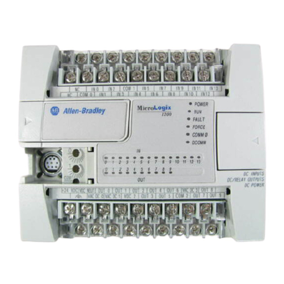
Chapter Hardware Overview Hardware Features The Bulletin 1762, MicroLogix 1200 programmable controller contains a power supply, input and output circuits, and a processor. The controller is available in 24 I/O and 40 I/O configurations. The hardware features of the controller are: Table 1.1 Hardware Features... -
Page 16: Component Descriptions
(4) fast 24V dc (1) high-speed 24V dc FET Component Descriptions MicroLogix 1200 Memory Module and/or Real-Time Clock The controller is shipped with a memory module port cover in place. You can order a memory module, real-time clock, or memory module and real-time clock as an accessory. -
Page 17: 1762 Expansion I/O
Hardware Overview 1762 Expansion I/O 1762 expansion I/O can be connected to the MicroLogix 1200 controller, as shown below. A maximum of six I/O modules, in certain combinations, NOTE may be connected to a controller. See Appendix F System Loading and Heat Dissipation to determine valid combinations. -
Page 18: Communication Cables
Series C or higher cables are required. NOTE Communication Options The MicroLogix 1200 can be connected to a personal computer. It can also be connected to the DH485 network using an Advanced Interface Converter (catalog number 1761-NET-AIC) and to the DeviceNet™... -
Page 19: Installing Your Controller
• C-UL under CSA C22.2 no. 142 • Class I, Division 2, Groups A, B, C, D (UL 1604, C-UL under CSA C22.2 no. 213) • CE compliant for all applicable directives • C-Tick compliant for all applicable acts. Allen-Bradley PLCs Publication 1762-UM001B-EN-P... -
Page 20: Compliance To European Union Directives
EN 61131-2 Programmable Controllers, Part 2 - Equipment Requirements and Tests. For specific information required by EN 61131-2, see the appropriate sections in this publication, as well as the following Allen-Bradley publications: • Industrial Automation Wiring and Grounding Guidelines for Noise Immunity, publication 1770-4.1... -
Page 21: Installation Considerations
Pollution Degree 2 is an environment where normally only non-conductive pollution occurs except that occasionally temporary conductivity caused by condensation shall be expected. Allen-Bradley PLCs Overvoltage Category II is the load level section of the electrical distribution system. At this level, transient voltages are controlled and do not exceed the impulse voltage capability of the products insulation. -
Page 22: Safety Considerations
Installing Your Controller Safety Considerations Safety considerations are an important element of proper system installation. Actively thinking about the safety of yourself and others, as well as the condition of your equipment, is of primary importance. We recommend reviewing the following safety considerations. Hazardous Location Considerations This equipment is suitable for use in Class I, Division 2, Groups A, B, C, D or non-hazardous locations only. -
Page 23: Disconnecting Main Power
This avoids the additional delay of power supply turn-off. The dc power supply should be powered directly from the fused secondary of the transformer. Power to the dc input and output circuits should be connected through a set of master control relay contacts. Allen-Bradley PLCs Publication 1762-UM001B-EN-P... -
Page 24: Periodic Tests Of Master Control Relay Circuit
The power rating is expressed in volt-amperes (VA). Power Supply Inrush During power-up, the MicroLogix 1200 power supply allows a brief inrush current to charge internal capacitors. Many power lines and control transformers can supply inrush current for a brief time. If the power source cannot supply this inrush current, the source voltage may sag momentarily. -
Page 25: Loss Of Power Source
Harmful contaminants or dirt could cause improper operation or damage to components. In extreme cases, you may need to use air conditioning to protect against Allen-Bradley PLCs heat build-up within the enclosure. Publication 1762-UM001B-EN-P... -
Page 26: Master Control Relay
Installing Your Controller Master Control Relay A hard-wired master control relay (MCR) provides a reliable means for emergency machine shutdown. Since the master control relay allows the placement of several emergency-stop switches in different locations, its installation is important from a safety standpoint. Overtravel limit switches or mushroom-head push buttons are wired in series so that when any of them opens, the master control relay is de-energized. -
Page 27: Using Emergency-Stop Switches
The following illustrations show the Master Control Relay wired in a grounded system. In most applications input circuits do not require MCR NOTE protection; however, if you need to remove power from all field devices, you must include MCR contacts in series with input power wiring. Allen-Bradley PLCs Publication 1762-UM001B-EN-P... -
Page 28: Schematic (Using Iec Symbols)
2-10 Installing Your Controller Schematic (Using IEC Symbols) 230V ac Disconnect Fuse 230V ac Circuits Isolation Operation of either of these contacts will Transformer remove power from the external I/O Master Control Relay (MCR) circuits, stopping machine motion. 115V ac Cat. -
Page 29: Schematic (Using Ansi/Csa Symbols)
NEC Class 2 for UL Listing 24 V dc (Lo) (Hi) Circuits Line Terminals: Connect to terminals of Power Supply (1762-L24AWA, 1762-L24BWA, Line Terminals: Connect to 24V dc terminals of 1762-L40AWA, and 1762-L40BWA). Power Supply (1762-L24BXB and 1762-L40BXB). Allen-Bradley PLCs Publication 1762-UM001B-EN-P... -
Page 30: Installing A Memory Module And/Or Real-Time Clock
2-12 Installing Your Controller Installing a Memory 1. Remove the memory module port cover. Module and/or Real-Time Clock 2. Align the connector on the memory module with the connector pins on the controller. 3. Firmly seat the memory module into the controller. Publication 1762-UM001B-EN-P... -
Page 31: Controller Mounting Dimensions
Allow 50 mm (2 in.) of space on all sides of the Expansion I/O Spacing controller system for adequate ventilation. Maintain spacing from enclosure walls, wireways, adjacent equipment, etc., as shown below. Side Side MicroLogix 1200 Bottom Allen-Bradley PLCs Publication 1762-UM001B-EN-P... -
Page 32: Mounting The Controller
2-14 Installing Your Controller Mounting the Controller MicroLogix™ 1200 controllers are suitable for use in an industrial environment when installed in accordance with these instructions. Specifically, this equipment is intended for use in clean, dry environments (Pollution degree 2 ) and to circuits not exceeding Over Voltage Category II (IEC 60664-1). -
Page 33: Din Rail Mounting
4. While pressing the controller down against the top of the rail, snap the bottom of the controller into position. 5. Leave the protective debris shield attached until you are finished wiring the controller and any other devices. Allen-Bradley PLCs Publication 1762-UM001B-EN-P... -
Page 34: Panel Mounting
Mount to panel using #8 or M4 screws. To install your controller using mounting screws: 1. Remove the mounting template from inside the back cover of the MicroLogix 1200 Programmable Controllers Installation Instructions, publication 1762-IN006C-MU-P. 2. Secure the template to the mounting surface. (Make sure your controller is spaced properly. -
Page 35: 1762 Expansion I/O Dimensions
(EN 50 022 - 35 x 7.5) or 35 x 15 mm (EN 50 022 - 35 x 15). Before mounting the module on a DIN rail, close the DIN rail latch. Press the DIN rail mounting area of the module against the DIN rail. The latch momentarily opens and locks into place. Allen-Bradley PLCs Publication 1762-UM001B-EN-P... -
Page 36: Panel Mounting
2-18 Installing Your Controller Use DIN rail end anchors (Allen-Bradley part number 1492-EA35 or 1492-EAH35) for vibration or shock environments. The following illustration shows the location of the end anchors. End Anchor End Anchor 1762 expansion I/O must be mounted horizontally as NOTE illustrated. -
Page 37: Connecting Expansion I/O
In Class I, Division 2 applications, all modules must be mounted in direct contact with each other as shown on page 2-19. If DIN rail mounting is used, an end stop must be installed ahead of the controller and after the last 1762 Allen-Bradley PLCs I/O module. Publication 1762-UM001B-EN-P... - Page 38 2-20 Installing Your Controller Publication 1762-UM001B-EN-P...
-
Page 39: Wiring Your Controller
Where paths must cross, their intersection should be perpendicular. Do not run signal or communications wiring and power NOTE wiring in the same conduit. Wires with different signal characteristics should be routed by separate paths. Allen-Bradley PLCs Publication 1762-UM001B-EN-P... - Page 40 Wiring Your Controller • Separate wiring by signal type. Bundle wiring with similar electrical characteristics together. • Separate input wiring from output wiring. • Label wiring to all devices in the system. Use tape, shrink-tubing, or other dependable means for labeling purposes. In addition to labeling, use colored insulation to identify wiring based on signal characteristics.
-
Page 41: Using Surge Suppressors
The diameter of the terminal screw head is 5.5 mm (0.220 in.). The input and output terminals of the MicroLogix 1200 controller are designed for a 6.35mm (0.25 in.) wide spade (standard for #6 screw for up to 14 AWG) or a 4 mm (metric #4) fork terminal. - Page 42 Suitable surge suppression methods for inductive ac load devices include a varistor, an RC network, or an Allen-Bradley surge suppressor, all shown below. These components must be appropriately rated to suppress the switching transient characteristic of the particular inductive device. See the table on page 3-5 for recommended suppressors.
-
Page 43: Recommended Surge Suppressors
Wiring Your Controller Recommended Surge Suppressors Use the Allen-Bradley surge suppressors shown in the following table for use with relays, contactors, and starters. Table 3.2 Recommended Surge Suppressors Device Coil Voltage Suppressor Catalog Number Bulletin 509 Motor Starter 120V ac... -
Page 44: Grounding The Controller
Wiring Your Controller Grounding the Controller In solid-state control systems, grounding and wire routing helps limit the effects of noise due to electromagnetic interference (EMI). Run the ground connection from the ground screw of the controller to the ground bus prior to connecting any devices. -
Page 45: Wiring Diagrams
The 24V dc sensor supply of the 1762-L24BWA should ATTENTION not be used to power output circuits. It should only be used to power input devices (e.g. sensors, switches). See Master Control Relay on page 2-8 for Allen-Bradley PLCs information on MCR wiring in output circuits. Publication 1762-UM001B-EN-P... - Page 46 Wiring Your Controller Figure 3.3 1762-L24BXB Group 1 Group 0 IN 0 IN 2 IN 5 IN 7 IN 9 IN 11 IN 13 IN 1 IN 3 IN 4 IN 6 IN 8 IN 10 IN 12 NEUT DC 3 DC 0 DC 1 Figure 3.4 1762-L40AWA...
-
Page 47: Terminal Groupings
Group 0 VAC/VDC 0 Group 1 VAC/VDC 1 Group 2 VAC/VDC 2 O/2 through O/3 1762-L40AWA Group 3 VAC/VDC 3 O/4 through O/7 Group 4 VAC/VDC 4 O/8 through O/11 Group 5 VAC/VDC 5 O/12 through O/15 Allen-Bradley PLCs Publication 1762-UM001B-EN-P... -
Page 48: Sinking And Sourcing Wiring Diagrams
VAC/VDC 4 O/12 through O/15 Sinking and Sourcing Any of the MicroLogix 1200 DC embedded input groups can be configured as sinking or sourcing depending on how the DC COM is Wiring Diagrams wired on the group. Refer to pages 3-11 through 3-15 for sinking and sourcing wiring diagrams. -
Page 49: 1762-L24Awa, 1762-L24Bwa And 1762-L24Bxb Wiring
+DCb IN 0 IN 2 IN 5 IN 7 IN 9 IN 11 IN 13 COM 1 IN 1 IN 3 IN 4 IN 6 IN 8 IN 10 IN 12 COM 0 +DCb -DCa +DCa Allen-Bradley PLCs Publication 1762-UM001B-EN-P... - Page 50 3-12 Wiring Your Controller Figure 3.9 1762-L24BWA Sourcing Input Wiring Diagram +DCb -DCa 24V dc Sensor Power -DCb IN 0 IN 2 COM 1 IN 5 IN 7 IN 9 IN 11 IN 13 IN 1 IN 3 IN 4 IN 6 IN 8 IN 10...
- Page 51 IN 10 IN 12 IN 14 IN 16 IN 18 IN 20 IN 22 IN 1 IN 3 IN 4 IN 6 IN 9 IN 11 IN 13 IN 15 IN 17 IN 19 IN 21 IN 23 Allen-Bradley PLCs Publication 1762-UM001B-EN-P...
- Page 52 3-14 Wiring Your Controller Figure 3.15 1762-L40BWA Sinking Input Wiring Diagram +DCb -DCb +DCa +DCc C O M IN 0 IN 2 IN 5 IN 7 IN 8 IN 10 IN 12 IN 14 IN 16 IN 18 IN 20 IN 22 C O M C O M...
- Page 53 DC 3 DC 5 DC 4 DC 0 DC 1 DC 2 Figure 3.20 1762-L40BXB Output Wiring Diagram -DCc -DCa -DCb -DCd +DCe -DCe NEUT DC 4 DC 0 DC 1 -DCe -DCd +DCa +DCb +DCd +DCc Allen-Bradley PLCs Publication 1762-UM001B-EN-P...
-
Page 54: Diagrams
To help reduce the effects of environmental noise, install the MicroLogix 1200 system in a properly rated (i.e. NEMA) enclosure. Make sure that the MicroLogix 1200 system is properly grounded. - Page 55 IN 7 -DC (Sinking) COM 0 +DC (Sourcing) +DC (Sinking) -DC (Sourcing) IN 8 IN 9 IN 10 IN 11 24V dc IN 12 IN 13 IN 14 IN 15 COM 1 -DC (Sinking) +DC (Sourcing) Allen-Bradley PLCs Publication 1762-UM001B-EN-P...
- Page 56 3-18 Wiring Your Controller Figure 3.24 1762-OA8 Wiring Diagram OUT 0 OUT 1 OUT 2 OUT 3 OUT 4 OUT 5 OUT 6 OUT 7 Figure 3.25 1762-OB8 Wiring Diagram +VDC OUT 0 OUT 1 OUT 2 OUT 3 OUT 4 OUT 5 24V dc (source) OUT 6...
- Page 57 DC COM Figure 3.27 1762-OW8 Wiring Diagram L1 VAC1 + VAC-VDC 1 OUT 0 L2 DC1 COM OUT 1 OUT 2 OUT3 L1 VAC2 + VAC-VDC2 OUT 4 L2 DC2 COM OUT 5 OUT 6 OUT 7 Allen-Bradley PLCs Publication 1762-UM001B-EN-P...
-
Page 58: Analog Wiring
3-20 Wiring Your Controller Figure 3.28 1762-OW16 Wiring Diagram VAC-VDC OUT 0 OUT 1 OUT 2 OUT 3 OUT 4 OUT 5 OUT 6 OUT 7 VAC-VDC OUT 8 OUT 9 OUT 10 OUT 11 OUT 12 OUT 13 OUT 14 OUT 15 Analog Wiring System Wiring Guidelines... - Page 59 The output type selection, current or voltage, is made by wiring to the appropriate terminals, Iout or Vout, and by the type/range selection bits in the Configuration Data File. Refer to MicroLogix 1200 and 1500 Programmable Controllers Instruction Set Reference Manual, publication number 1762-RM001C-EN-P.
- Page 60 3-22 Wiring Your Controller 1762-IF2OF2 Wiring The following illustration shows the 1762-IF2OF2 analog expansion I/O terminal block. Figure 3.29 1762-IF2OF2 Terminal Block Layout IN 0 (+) IN 0 (-) IN 1 (+) IN 1 (-) V Out 0 I Out 0 V Out 1 I Out 1 Common connected...
- Page 61 Select the input type, current or voltage, using the switches located on the module’s circuit board and the input type/range selection bits in the Configuration Data File. Refer to MicroLogix 1200 and 1500 Programmable Controllers Instruction Set Reference Manual, publication number 1762-RM001C-EN-P.
- Page 62 3-24 Wiring Your Controller Figure 3.32 1762-IF4 Terminal Block Layout IN 0 (+) IN 0 (-) IN 1 (+) IN 1 (-) IN 2 (+) IN 2 (-) IN 3 (+) IN 3 (-) Commons internally connected. Figure 3.33 Differential Sensor Transmitter Types IN 0 (+) Analog Sensor IN 0 (-)
-
Page 63: Communication Connections
• connecting to RS-232 port • connecting to DH485 network • connecting to AIC+ • DeviceNet communications Default Communication The MicroLogix 1200 has the following default communication configuration. Configuration The default configuration is present when: NOTE • The controller is powered-up for the first time. -
Page 64: Using The Communications Toggle Push Button
NOTE and held for one second to activate. Connecting to the There are two ways to connect the MicroLogix 1200 programmable controller to your personal computer using the DF1 protocol: using a RS-232 Port point-to-point connection, or using a modem. Descriptions of these methods follow. -
Page 65: Making A Df1 Point-To-Point Connection
2707-NC11 Series B or later 2m (6.5 ft) Making a DF1 Point-to-Point Connection You can connect the MicroLogix 1200 programmable controller to your personal computer using a serial cable (1762-CBL-PM02) from your personal computer’s serial port to the controller. The recommended protocol for this configuration is DF1 Full-Duplex. -
Page 66: Using A Modem
Isolated Modem Connection Using an AIC+ to isolate the modem is illustrated below. 24V dc MicroLogix 1200 MicroLogix 1200 provides power to the AIC+ or an external power supply may be used. See Appendix F, System Loading and Heat Dissipation. TERM... - Page 67 15.24 m (50 ft) with a 25-pin or 9-pin connector. Refer to the following typical pinout: DTE Device DCE Device (AIC+, (Modem, MicroLogix, PanelView, etc.) SLC, PLC, etc.) 9-Pin 25-Pin 9-Pin GND 7 CTS 5 RTS 4 Allen-Bradley PLCs Publication 1762-UM001B-EN-P...
-
Page 68: Connecting To A Df1 Half-Duplex Network
Communication Connections Connecting to a DF1 Half-Duplex Network Use this diagram for DF1 Half-Duplex Master-Slave protocol without hardware handshaking. SLC 5/03 processor MicroLogix 1200 Master 1761-CBL-AM00 or 1761-CBL-HM02 1761-CBL-AP00 or 1761-CBL-PM02 DF1 Slave radio modem or lease line AIC+ straight 9-25 pin cable... -
Page 69: Recommended Tools
Communication Connections Connecting to a DH485 The following illustration shows how to connect to a DH485 network. Network MicroLogix DH485 Network MicroLogix 1200 connection from port 1 or port 2 to MicroLogix 1761-CBL-AM00 PC to port 1 or 1761-CBL-HM02 or port 2... -
Page 70: Dh485 Communication Cable
Use these instructions for wiring the Belden #3106A or #9842 cable. (See Cable Selection Guide on page 4-11 if you are using standard Allen-Bradley cables.) Connecting the Communication Cable to the DH485 Connector A daisy-chained network is recommended. Do not... - Page 71 Terminal 5 - (Data A) (1) To prevent confusion when installing the communication cable, cut back the white with blue stripe wire immediately after the insulation jacket is removed. This wire is not used by DH485. Allen-Bradley PLCs Publication 1762-UM001B-EN-P...
-
Page 72: Grounding And Terminating The Dh485 Network
1219 m (4000ft) Maximum Jumper Connecting the AIC+ The AIC+, catalog number 1761-NET-AIC, enables a MicroLogix 1200 to connect to a DH485 network. The AIC+ has two RS-232 ports and one isolated RS-485 port. Typically, there is one AIC+ for each MicroLogix 1200. -
Page 73: Cable Selection Guide
(1) External power supply required unless the AIC+ is powered by the device connected to port 2, then the selection switch should be set to cable . (2) Series C or higher cables are required. Allen-Bradley PLCs Publication 1762-UM001B-EN-P... - Page 74 4-12 Communication Connections 1761-CBL-HM02 1761-CBL-AM00 Cable Length Connections from to AIC+ External Power Power Supply Selection Switch Setting Required 45 cm (17.7 in) MicroLogix 1000, 1200, or 1500 port 2 cable 1761-CBL-AM00 2m (6.5 ft) 1761-CBL-HM02 to port 2 on another AIC+ port 2 external (1) External power supply required unless the AIC+ is powered by the device connected to port 2, then the selection switch should be set to cable .
- Page 75 (1) External power supply required unless the AIC+ is powered by the device connected to port 2, then the selection switch should be set to cable . 1761-CBL-PM02 Series C (or equivalent) Cable Wiring Diagram Programming Controller Device 9-Pin D-Shell 8-Pin Mini Din 1761-CBL-PM02 Series C or later Cable 8-pin Mini Din 6 8 7 9-pin D-shell Allen-Bradley PLCs Publication 1762-UM001B-EN-P...
-
Page 76: Recommended User-Supplied Components
If you are making a cable to connect to port 2, you must configure your cable to connect to the Allen-Bradley cable shown above. (3) In the 1761-CBL-PM02 cable, pins 4 and 6 are jumpered together within the DB-9 connector. -
Page 77: Safety Considerations
Installing and Attaching the AIC+ 1. Take care when installing the AIC+ in an enclosure so that the cable connecting the MicroLogix 1200 controller to the AIC+ does not interfere with the enclosure door. 2. Carefully plug the terminal block into the RS-485 port on the AIC+ you are putting on the network. - Page 78 Power Options Below are two options for powering the AIC+: • Use the 24V dc user power supply built into the MicroLogix 1200 controller. The AIC+ is powered through a hard-wired connection using a communication cable (1761-CBL-HM02, or equivalent) connected to port 2.
-
Page 79: Devicenet Communications
Communication Connections 4-17 DeviceNet You can connect a MicroLogix 1200 to a DeviceNet network using the DeviceNet Interface (DNI), catalog number 1761-NET-DNI. For additional Communications information on using the DNI, refer to the DeviceNet Interface User Manual, publication 1761-6.5. The following figure shows the external wiring connections of the DNI. - Page 80 4-18 Communication Connections Publication 1762-UM001B-EN-P...
-
Page 81: Chapter 5 Trim Pot Operation
Trim pot file data is updated continuously whenever the controller is powered-up. Trim Pot Information Function File The composition of the Trim Pot Information (TPI) Function File is described in the MicroLogix 1200 and 1500 Programmable Controllers Instruction Set Reference Manual, publication 1762-RM001C-EN-P. Allen-Bradley PLCs Publication 1762-UM001B-EN-P... -
Page 82: Error Conditions
Using Trim Pots Error Conditions Error conditions of the TPI Function File are described in the MicroLogix 1200 and 1500 Programmable Controllers Instruction Set Reference Manual, publication 1762-RM001C-EN-P. Publication 1762-UM001B-EN-P... -
Page 83: Real-Time Clock Operation
If an RTC is installed while the MicroLogix 1200 is in a run or test mode, the module is not recognized until either a power cycle occurs or until the controller is placed in a non-executing mode (program mode, suspend mode or fault condition). -
Page 84: Writing Data To The Real-Time Clock
Using Real-Time Clock and Memory Modules The following table indicates the accuracy of the RTC for various temperatures. Table 6.1 RTC Accuracy Ambient Temperature Accuracy 0°C (+32°F) +34 to -70 seconds/month +25°C (+77°F) +36 to -68 seconds/month +40°C (+104°F) +29 to -75 seconds/month +55°C (+131°F) -133 to -237 seconds/month (1) These numbers are maximum worst case values over a 31-day month. -
Page 85: Memory Module Operation
(run or test) mode. To enable this feature, set the S:2/9 bit in the system status file. See “Status System File” in the MicroLogix 1200 and 1500 Programmable Controllers Instruction Set Reference Manual, Publication 1762-RM001C-EN-P for more information. -
Page 86: Data File Download Protection
The memory module can be installed or removed at any time without risk of damage to either the memory module or the controller. If a memory module is installed while the MicroLogix 1200 is executing, the memory module is not recognized until either a power cycle occurs, or until the controller is placed in a non-executing mode (program mode, suspend mode or fault condition). -
Page 87: Controller Specifications
Operating: 10 to 500 Hz, 5G, 0.030 in. max. peak-to-peak, 2 hours each axis Relay Operation: 1.5G Shock Operating: 30G; 3 pulses each direction, each axis Relay Operation: 7G Non-Operating: 50G panel mounted (40G DIN Rail mounted); 3 pulses each direction, each axis Allen-Bradley PLCs Publication 1762-UM001B-EN-P... - Page 88 Specifications Table A.1 General Specifications Description 1762- L24AWA L24BWA L24BXB L40AWA L40BWA L40BXB Agency Certification •UL 508 •C-UL under CSA C22.2 no. 142 •Class I, Div. 2, Groups A, B, C, D (UL 1604, C-UL under CSA C22.2 no. 213) •CE/C-Tick compliant for all applicable directives Electrical/EMC The controller has passed testing at the following levels:...
- Page 89 8A, 30˚C (86˚F) 1.75 1.5A, 30˚C (86˚F) 1.25 5.5A, 55˚C (131˚F) 1.0A, 55˚C (131˚F) Valid Valid 0.75 Range Range 0.25 10˚C 30˚C 50˚C 70˚C (50˚F) (86˚F) (122˚F) (158˚F) 10˚C 30˚C 50˚C 70˚C (50˚F) (86˚F) (122˚F) (158˚F) Temperature Temperature Allen-Bradley PLCs Publication 1762-UM001B-EN-P...
- Page 90 Specifications Table A.4 BXB FET Output Specifications Description General Operation High Speed Operation (Output 2 Only) Surge Current per Point: • peak current • 4.0A • Not Applicable • maximum surge duration • 10 msec • Not Applicable • maximum rate of repetition at 30°C (86°F) •...
- Page 91 Output Group to Output Verified by one of the following dielectric tests: 1836V ac for 1 Group Isolation second or 2596V dc for 1second 265V ac Working Voltage (basic insulation) 150V ac Working Voltage (IEC Class 2 reinforced insulation). Allen-Bradley PLCs Publication 1762-UM001B-EN-P...
- Page 92 Specifications Table A.10 Working Voltage (1762-L24BWA, 1762-L40BWA) Description 1762-L24BWA, 1762-L40BWA Power Supply Input to Verified by one of the following dielectric tests:1836V ac for 1 second Backplane Isolation or 2596V dc for 1 second 265V ac Working Voltage (IEC Class 2 reinforced insulation) Input Group to Verified by one of the following dielectric tests: 1200V ac for 1 second Backplane Isolation and...
-
Page 93: Expansion I/O Specifications
2 kV common mode, 1 kV differential mode Conducted Immunity (IEC1000-4-6) 10V, 0.15 to 80 MHz (1) Conducted Immunity frequency range may be 150 kHz to 30 MHz if the Radiated Immunity frequency range is 30 MHz to 1000 MHz. Allen-Bradley PLCs Publication 1762-UM001B-EN-P... - Page 94 Specifications Table A.13 Input Specifications Specification 1762-IA8 1762-IQ8 1762-IQ16 Approximate Shipping Weight 209g (0.46 lbs.) 200g (0.44 lbs.) 230 g (0.51 lbs.) (With Carton) Voltage Category 100/120V ac 24V dc (sink/source) 24V dc (sink/source) Operating Voltage Range 79V ac to 132V ac at 47 Hz to 63 Hz 10 to 30V dc at 30°C (86°F) 10 to 30V dc at 30°C (86°F) 10 to 26.4V dc at 55°C (131°F) 10 to 26.4V dc at 55°C (131°F)
- Page 95 30°C (86°F) for a duration of (86°F) for a duration of 10 msec.) 10 msec.) Power Supply 6 (The module may not be more than 6 modules away from the power supply.) Distance Rating Allen-Bradley PLCs Publication 1762-UM001B-EN-P...
- Page 96 A-10 Specifications Table A.14 Output Specifications Specification 1762-OA8 1762-OB8 1762-OB16 1762-OW8 1762-OW16 Isolated Group 1: Outputs 0 to 3 Group 1: Outputs 0 to Group 1: Outputs 0 to Group 1: Outputs 0 to Group 1: Outputs 0 to Groups Group 2: Outputs 4 to 7 Group 2: Outputs 4 to Group 2: Outputs 8 to...
-
Page 97: Analog Modules
1 kV galvanic gun Conducted Immunity (IEC1000-4-6) 10V, 0.15 to 80 MHz (1) Conducted Immunity frequency range may be 150 kHz to 30 MHz if the Radiated Immunity frequency range is 30 MHz to 1000 MHz. Allen-Bradley PLCs Publication 1762-UM001B-EN-P... - Page 98 A-12 Specifications Table A.17 Common Specifications Specification 1762-IF2OF2 1762-IF4 Approximate Shipping 240g (0.53 lbs.) Weight (with carton) Bus Current Draw (max.) 40 mA at 5V dc 40 mA at 5V dc 105 mA at 24V dc 50 mA at 24V dc Analog Normal Voltage: 0 to 10V dc Voltage: -10 to +10V dc...
- Page 99 Table A.20 Valid Input/Output Data Word Formats/Ranges for 1762-IF2OF2 Normal Operating Full Scale Range RAW/Proportional Scaled-for-PID Range Data 10.5V dc 32760 16380 0V to 10V dc 0.0V dc 21.0mA 32760 16380 20.0mA 31200 15600 4mA to 20mA 4.0mA 6240 3120 0.0mA Allen-Bradley PLCs Publication 1762-UM001B-EN-P...
-
Page 100: Controller Dimensions
A-14 Specifications Controller Dimensions See Controller Mounting Dimensions on page 2-13. Expansion I/O See 1762 Expansion I/O Dimensions on page 2-17. Dimensions Publication 1762-UM001B-EN-P... -
Page 101: Micrologix 1200 Replacement Kits
Appendix Replacement Parts MicroLogix 1200 Controllers Replacement Doors Replacement Kits Catalog Number 1762-RPLDR1 The controller door kit consists of: • Two memory module doors • Two RS-232 communication port doors • Two expansion bus doors Controller Replacement Door Labels Catalog Number 1762-RPLTLBL1 The controller terminal door label kit consists of: •... -
Page 102: Controller 24-Point Terminal Doors
Replacement Parts Controller 24-Point Terminal Doors Catalog Number 1762-RPLTDR24 The 24-point controller terminal door kit consists of: • Four terminal doors • Four sub-terminal covers. (Enough doors for two 24-point controllers.) Controller 40-Point Terminal Doors Catalog Number 1762-RPLTDR40 The 40-point controller terminal door kit consists of: •... -
Page 103: Understanding The Controller Led Status
Output is not energized amber Output is engerized (logic status) Normal Operation The POWER and RUN LEDs are on. If a force condition is active, the Allen-Bradley PLCs FORCE LED turns on and remains on until all forces are removed. Publication 1762-UM001B-EN-P... -
Page 104: Error Conditions
Power and Hardware faulted Processor Hardware Cycle power. Contact your local FAULT Error Allen-Bradley representative if LEDs on the error persists. solid Loose Wiring Verify connections to the controller. Power LED Application fault... -
Page 105: Controller Error Recovery Model
Return controller to RUN or status? any of the REM test modes. Refer to page C-2 for Refer to page C-2 for probably cause and probable cause and recommended action. recommended action. Test and verify system operation. Allen-Bradley PLCs Publication 1762-UM001B-EN-P... -
Page 106: Analog Expansion I/O Diagnostics And Troubleshooting
Channel over-range or under-range conditions are reported in the module’s input data table. Module hardware errors are reported in the controller’s I/O status file. Refer to the MicroLogix 1200 and 1500 Programmable Controllers Instruction Set Reference Manual, publication 1762-RM001C-EN-P for more information. -
Page 107: Module Error Definition Table
These types of module errors are typically reported in the controller’s I/O status file. Refer to the MicroLogix 1200 and 1500 Programmable Controllers Instruction Set Reference Manual, publication 1762-RM001C-EN-P for more information. -
Page 108: Error Codes
Troubleshooting Your System Hardware Errors General or module-specific hardware errors are indicated by module error code 2. See Table C.5. Configuration Errors If you set the fields in the configuration file to invalid or unsupported values, the module ignores the invalid configuration, generates a non-critical error, and keeps operating with the previous configuration. -
Page 109: Calling Rockwell Automation For Assistance
• controller type, series letter, revision letter, and firmware (FRN) Assistance number of the controller • controller LED status • controller error codes (Refer to MicroLogix 1200 and 1500 Programmable Controllers Instruction Set Reference Manual, Publication 1762-RM001C-EN-P for error code information.) Allen-Bradley PLCs... - Page 110 Troubleshooting Your System Publication 1762-UM001B-EN-P...
-
Page 111: Appendix D Preparing For Upgrade
Prepare the Controller for Updating Controller Configuration The controller must be configured for default communications (use communications toggle push button; DCOMM LED on) and be in the Program mode to allow the download of a new operating system. Allen-Bradley PLCs Publication 1762-UM001B-EN-P... -
Page 112: Sequence Of Operation
Using Control Flash to Upgrade Your Operating System Sequence of Operation The following steps detail the key events in the upgrade process. 1. Controller mode and communications parameters are checked. 2. Download begins. 3. During the download, the Force, Battery, and Comms LEDs perform a walking bit pattern. -
Page 113: Communication Interface
See Chapter 4 Communication Connections for information about required network devices and accessories. RS-232 Communication The communications port on the MicroLogix 1200 utilizes an RS-232 interface. RS-232 is an Electronics Industries Association (EIA) standard Interface that specifies the electrical and mechanical characteristics for serial binary communication. -
Page 114: Df1 Full-Duplex Operation
Stop Bits not a setting, always 1 Example DF1 Full-Duplex Connections For information about required network connecting equipment, see chapter 3, Connecting the System. 1761-CBL-AM00 or 1761-CBL-HM02 Personal Computer MicroLogix 1200 TERM SHLD CHS GND Optical Personal Computer DC SOURCE... -
Page 115: Df1 Half-Duplex Protocol
National Standards Institute ANSI - X3.28-1976 specification subcategory D1). In contrast to DF1 Full-Duplex, communication takes place in one direction at a time. You can use the RS-232 port on the MicroLogix 1200 as both a Half-Duplex programming port and a Half-Duplex peer-to-peer messaging port. - Page 116 Understanding the Communication Protocols When the system driver is DF1 Half-Duplex Slave, available parameters include: Table E.2 DF1 Half-Duplex Configuration Parameters Parameter Options Baud Rate 300, 600, 1200, 2400, 4800, 9600, 19.2K, 38.4K Parity none, even Source ID (Node Address) 0 to 254 decimal Control Line no handshaking, handshaking...
-
Page 117: Considerations When Communicating As A Df1 Slave On A Multi-Drop Link
As these time periods grow, the following values may need to be changed to avoid loss of communication: • programming software: increase poll timeout and reply timeout values • MicroLogix Programmable Controllers: increase poll timeout and reply timeout values Allen-Bradley PLCs Publication 1762-UM001B-EN-P... -
Page 118: Using Modems With Micrologix 1200 Programmable Controllers
Using Modems with MicroLogix 1200 Programmable Controllers The types of modems you can use with MicroLogix 1200 controllers include dial-up phone modems, leased-line modems, radio modems and line drivers. For point-to-point Full-Duplex modem connections that do not require any modem handshaking signals to operate, use DF1 Full-Duplex protocol with no handshaking. - Page 119 Dial-Up Phone Modems Some dial-up phone line modems support point-to-point Full-Duplex communications. A MicroLogix 1200 controller, on the receiving end of the dial-up connection, can be configured for DF1 Full-Duplex protocol with or without handshaking. The modem connected to the MicroLogix controller should support auto-answer.
-
Page 120: Dh485 Communication Protocol
Understanding the Communication Protocols DH485 Communication The information in this section describes the DH485 network functions, network architecture, and performance characteristics. It will also help Protocol you plan and operate a MicroLogix on a DH485 network. DH485 Network Description The DH485 protocol defines the communication between multiple devices that coexist on a single pair of wires. -
Page 121: Dh485 Configuration Parameters
See Appendix E Software Considerations for tips on setting the parameters listed above. Devices that use the DH485 Network In addition to the MicroLogix 1200 controllers, the devices shown in the following table also support the DH485 network. Table E.4 Allen-Bradley Devices that Support DH485 Communication... -
Page 122: Important Dh485 Network Planning Considerations
E-10 Understanding the Communication Protocols Table E.4 Allen-Bradley Devices that Support DH485 Communication Catalog Description Installation Function Publication Number 1747-DTAM, DTAM, DTAM Plus, Panel Mount Provides electronic operator interface for SLC 500 processors. 1747-6.1 2707-L8P1, and DTAM Micro 2707-800, -L8P2, -L40P1,... - Page 123 0.15m (6 in.) from ac power lines of less than 20A, 0.30m (1 ft) from lines greater than 20A, but only up to 100K VA, and 0.60m (2 ft) from lines of 100K VA or more. Allen-Bradley PLCs Publication 1762-UM001B-EN-P...
- Page 124 E-12 Understanding the Communication Protocols • If you run the cable through a contiguous metallic wireway or conduit, keep the communication cable at least 0.08m (3 in.) from ac power lines of less than 20A, 0.15m (6 in.) from lines greater than 20A, but only up to 100K VA, and 0.30m (1 ft) from lines of 100K VA or more.
-
Page 125: Example Dh485 Connections
The best network performance occurs at the highest baud rate, which is 19200. This is the default baud rate for a MicroLogix 1200 device on the DH485 network. All devices must be at the same baud rate. This rate is stored in the controller Communications Status file (CS0:5/8 to CS0:5/15). - Page 126 E-14 Understanding the Communication Protocols DH485 Network with a MicroLogix 1200 Controller MicroLogix 1200 connection from port 1 or port 2 to MicroLogix 1761-CBL-AP00 or 1761-CBL-AM00 or connection from port 1 1761-CBL-PM02 1761-CBL-HM02 or port 2 to PC 1761-CBL-AP00 or...
- Page 127 SLC 5/04 processor as the bridge connection. When using this method (as shown in the illustration below): • PLC-5 devices can send read and write commands to MicroLogix 1200 controllers. • MicroLogix 1200 controllers can respond to MSG instructions received.
-
Page 128: Modbus Communication Protocol
Modbus protocol allows a single master to communicate with a maximum of 255 slave devices. For more information on the MicroLogix 1200 configuration parameters for Modbus Slave RTU (Remote Terminal Unit transmission mode) protocol, refer to the MicroLogix 1200 and 1500 Programmable Controllers Instruction Set Reference Manual, publication 1762-RM001C-EN-P. -
Page 129: Ascii
You can use ASCII by configuring the RS-232 port, channel 0 for ASCII driver. Refer to the MicroLogix 1200 and MicroLogix 1500 Programmable Controllers Instruction Set Reference Manual, publication 1762-RM001C-EN-P for detailed configuration information. - Page 130 E-18 Understanding the Communication Protocols Publication 1762-UM001B-EN-P...
-
Page 131: System Loading Limitations
24V dc (mA) 1761-NET-AIC when powered by the base unit communications port, selector switch in the up position Subtotal 1: (1) This is an optional accessory. Current is consumed only if the accessory is installed. Allen-Bradley PLCs Publication 1762-UM001B-EN-P... - Page 132 System Loading and Heat Dissipation Table F.2 Calculating the Current for Expansion I/O n x A n x B Catalog Number Number of Device Current Requirements Calculated Current Modules (max) at 5V dc (mA) at 24V dc (mA) at 5V dc (mA) at 24V dc (mA) 1762-IA8 1762-IQ8...
-
Page 133: System Loading Worksheet
24V dc (mA) 1761-NET-AIC when powered by the base unit communications port, selector switch in the up position Subtotal 1: (1) This is an optional accessory. Current is consumed only if the accessory is installed. Allen-Bradley PLCs Publication 1762-UM001B-EN-P... - Page 134 System Loading and Heat Dissipation Table F.6 Calculating the Current for Expansion I/O n x A n x B Catalog Number Number of Device Current Requirements Calculated Current Modules at 5V dc (mA) at 24V dc (mA) at 5V dc (mA) at 24V dc (mA) 1762-IA8 1762-IQ8...
-
Page 135: System Loading Example Calculations (40-Point Controller
24V dc (mA) (mA) 1761-NET-AIC when powered by the base unit communications port, selector switch in the up position Subtotal 1: (1) This is an optional accessory. Current is consumed only if the accessory is installed. Allen-Bradley PLCs Publication 1762-UM001B-EN-P... - Page 136 System Loading and Heat Dissipation Table F.10 Calculating the Current for Expansion I/O n x A n x B Catalog Number Number of Device Current Requirements (max) Calculated Current Modules at 5V dc (mA) at 24V dc (mA) at 5V dc (mA) at 24V dc (mA) 1762-IA8 1762-IQ8...
-
Page 137: System Loading Worksheet
24V dc (mA) 1761-NET-AIC when powered by the base unit communications port, selector switch in the up position Subtotal 1: (1) This is an optional accessory. Current is consumed only if the accessory is installed. Allen-Bradley PLCs Publication 1762-UM001B-EN-P... - Page 138 System Loading and Heat Dissipation Table F.14 Calculating the Current for Expansion I/O n x A n x B Catalog Number Number of Device Current Requirements Calculated Current Modules at 5V dc (mA) at 24V dc (mA) at 5V dc (mA) at 24V dc (mA) 1762-IA8 1762-IQ8...
- Page 139 System Loading: System Loading: = (________ mA x 24V) + (________ mA x 5V) + (________ mA x 24V) = __________ mW + __________ mW + __________ mW = __________ mW 16 Watts = __________ W Allen-Bradley PLCs Publication 1762-UM001B-EN-P...
-
Page 140: Calculating Heat Dissipation
F-10 System Loading and Heat Dissipation Calculating Heat Use the following table when you need to determine the heat dissipation of your system for installation in an enclosure. For System Loading, take Dissipation the value from the appropriate system loading worksheets on pages F-3, F-5, F-7 or F-9: Table F.17 Heat Dissipation Catalog Number... -
Page 141: Glossary
Glossary The following terms are used throughout this manual. Refer to the Allen-Bradley Industrial Automation Glossary, Publication Number AG-7.1, for a complete guide to Allen-Bradley technical terms. address A character string that uniquely identifies a memory location. For example, I:1/0 is the memory address for the data located in the Input file location word1, bit 0. - Page 142 2) A device that transmits a fixed number of pulses for each revolution. executing mode Any run or test mode. expansion I/O Expansion I/O is I/O that is connected to the controller via a bus or cable. MicroLogix 1200 controllers use Bulletin 1762 expansion I/O. Publication 1762-UM001B-EN-P...
- Page 143 In turn, the controller sets the output instructions to true or false. instruction set The set of general purpose instructions available with a given controller. I/O (Inputs and Outputs) Consists of input and output devices that provide and/or receive data from the controller. Allen-Bradley PLCs Publication 1762-UM001B-EN-P...
- Page 144 Glossary jump Change in normal sequence of program execution, by executing an instruction that alters the program counter (sometimes called a branch). In ladder programs a JUMP (JMP) instruction causes execution to jump to a labeled rung. ladder logic A program written in a format resembling a ladder-like diagram. The program is used by a programmable controller to control devices.
- Page 145 The ON delay time is a measure of the time required for the controller logic to recognize that a signal has been presented at the input terminal of the controller. one-shot Allen-Bradley PLCs A programming technique that sets a bit for only one program scan. Publication 1762-UM001B-EN-P...
- Page 146 Glossary online Describes devices under direct communication. For example, when RSLogix 500 is monitoring the program file in a controller. operating voltage For inputs, the voltage range needed for the input to be in the On state. For outputs, the allowable range of user-supplied voltage. output device A device, such as a pilot light or a motor starter coil, that is controlled by the controller.
- Page 147 I/O circuit — typically, a sourcing device or circuit provides a path to the source, high, or positive side of power supply. status The condition of a circuit or system, represented as logic 0 (OFF) or 1 Allen-Bradley PLCs (ON). Publication 1762-UM001B-EN-P...
- Page 148 Glossary terminal A point on an I/O module that external I/O devices, such as a push button or pilot light, are wired to. throughput The time between when an input turns on and the corresponding output turns on. true The status of an instruction that provides a continuous logical path on a ladder rung.
- Page 149 DF1 Full-Duplex protocol system wiring guidelines DF1 isolated point-to-point connection 3-20 troubleshooting DH485 network application connecting to DF1 Half-Duplex network Glossary-1 contacting Rockwell Automation for assistance contactors (bulletin 100), surge suppressors for control profile Glossary-2 Allen-Bradley PLCs Publication 1762-UM001B-EN-P...
- Page 150 Index ControlFlash DIN rail Glossary-2 missing/corrupt OS LED pattern disconnecting main power sequence of operation download Glossary-2 using DTE (Data Terminal Equipment) Glossary-2 controller Glossary-1 grounding I/O wiring 3-16 Electronics Industries Association (EIA) installation EMC Directive LED status Glossary-2 LED status error conditions encoder Glossary-2 LED status normal operation...
- Page 151 Glossary-5 LED (Light Emitting Diode) Glossary-4 nominal input current Glossary-5 LIFO (Last-In-First-Out) Glossary-4 normally closed Glossary-5 logic Glossary-4 normally open Glossary-5 low byte Glossary-4 null modem cable offline Glossary-5 offset Glossary-5 Allen-Bradley PLCs off-state leakage current Glossary-5 Publication 1762-UM001B-EN-P...
- Page 152 Index one-shot replacement parts Glossary-5 online reserved bit Glossary-6 Glossary-7 operating voltage restore Glossary-6 Glossary-7 output device retentive data Glossary-6 Glossary-7 Rockwell Automation support local product support questions or comments on this manual planning considerations for a network E-10 technical product assistance power considerations RS-232 Glossary-7...
- Page 153 3-18 using emergency-stop switches 1762-OW16 3-20 using memory modules 1762-OW8 3-19 using real-time clock L1762-L40AWA input 3-13 using trim pots terminal block layouts 3-22 3-24 wiring diagrams wiring recommendation wiring your controller workspace Glossary-8 write Glossary-8 Allen-Bradley PLCs Publication 1762-UM001B-EN-P...
- Page 154 Index Publication 1762-UM001B-EN-P...
- Page 155 Cover Allen-Bradley PLCs...
- Page 156 Publication 1762-UM001B-EN-P - November 2000 PN 40072-078-01(B) Supersedes Publication 1762-UM001A-EN-P - January 2000 © 2000 Rockwell International Corporation. Printed in the U.S.A.