
Related Manuals for Dell Aurora R6


Summary of Contents for Dell Aurora R6
- Page 1 Aurora R6 Service Manual Computer Model: Alienware Aurora R6 Regulatory Model: D23M Regulatory Type: D23M001...
- Page 2 WARNING: A WARNING indicates a potential for property damage, personal injury, or death. Copyright © 2017 Dell Inc. or its subsidiaries. All rights reserved. Dell, EMC, and other trademarks are trademarks of Dell Inc. or its subsidiaries. Other trademarks may be trademarks of their respective owners.
-
Page 3: Table Of Contents
Contents Before working inside your computer..... 12 ...............12 Before you begin ..............12 Safety instructions ..............13 Recommended tools .................. 14 Screw list After working inside your computer......16 Technical overview............ 17 ............18 Inside view of your computer ............19 System-board components Removing the stability foot........21 ................. - Page 4 Removing the top-cover assembly......34 ................34 Prerequisites ................. 34 Procedure Replacing the top-cover assembly......40 ................. 40 Procedure ................40 Post-requisites Removing the bottom cover........41 ................41 Prerequisites ................. 42 Procedure Replacing the bottom cover........44 ................. 44 Procedure ................44 Post-requisites Removing the 3.5-inch hard drive......
- Page 5 Removing the hard-drive cage......... 53 ................. 53 Procedure ................54 Prerequisites Replacing the hard-drive cage......... 55 ................. 55 Procedure ................55 Post-requisites Removing the power-supply unit......56 ................56 Prerequisites ................. 56 Procedure Replacing the power-supply unit......63 ................. 63 Procedure ................63 Post-requisites Removing the processor-cooling assembly...
- Page 6 Removing the memory modules......71 ................71 Prerequisites ................. 71 Procedure Replacing the memory modules......73 ................. 73 Procedure ................75 Post-requisites Removing the solid-state drive........ 76 ................76 Prerequisites ................. 76 Procedure Replacing the solid-state drive.........78 ................. 78 Procedure ................79 Post-requisites Removing the graphics card........
- Page 7 Replacing the processor fan and heat-sink assembly..............86 ................. 86 Procedure ................86 Post-requisites Removing the processor...........87 ................87 Prerequisites ................. 87 Procedure Replacing the processor...........89 ................. 89 Procedure ................90 Post-requisites Removing the wireless card........91 ................91 Prerequisites ................. 91 Procedure Replacing the wireless card........
- Page 8 Replacing the front-chassis fan......102 ................102 Procedure .................102 Post-requisites Removing the top-chassis fan........103 ................103 Prerequisites ................103 Procedure Replacing the top-chassis fan........106 ................106 Procedure .................106 Post-requisites Removing the optical drive........107 ................107 Prerequisites ................107 Procedure Replacing the optical drive........111 ................111 Procedure .................
- Page 9 Replacing the power-button board......119 ................119 Procedure ................. 119 Post-requisites Removing the rear trim cover.........120 ................120 Prerequisites ................120 Procedure Replacing the rear trim cover......... 122 ................122 Procedure .................122 Post-requisites Removing the system board........123 ................123 Prerequisites ................124 Procedure Replacing the system board........127 ................
- Page 10 ..............138 Post-requisites Flashing the BIOS............139 Technology and components......... 140 ..................140 Audio ..........140 Downloading the audio driver ..........140 Identifying the audio controller ..........141 Changing the audio settings ................. 141 Graphics ...........142 Downloading the graphics driver ..........142 Identifying the display adapter ..........
- Page 11 ....152 Identifying the hard drive in BIOS setup program ................... 152 Chipset ..........152 Downloading the chipset driver ............152 Identifying the chipset .................. 153 Memory ......154 Checking the system memory in Windows .... 154 Checking the system memory in BIOS setup program ..........
-
Page 12: Before Working Inside Your Computer
Use the following safety guidelines to protect your computer from potential damage and ensure your personal safety. WARNING: Before working inside your computer, read the safety information that shipped with your computer. For more safety best practices, see the Regulatory Compliance home page at www.dell.com/regulatory_compliance. -
Page 13: Recommended Tools
CAUTION: You should only perform troubleshooting and repairs as authorized or directed by the Dell technical assistance team. Damage due to servicing that is not authorized by Dell is not covered by your warranty. See the safety instructions that shipped with the product or at www.dell.com/regulatory_compliance. -
Page 14: Screw List
Screw list The following table provides the list of screws that are used for securing different components to Alienware Aurora R5. Table 1. Screw list Component Secured to Screw type Quantit Screw image 3.5-inch hard-drive cage Chassis #6-32 X 1/4'' 2.5-inch hard-drive cage Chassis #6-32 X 1/4''... - Page 15 Component Secured to Screw type Quantit Screw image Processor-cooling assembly Chassis #6-32 X 1/4'' bracket Processor-cooling assembly Processor- #6-32 X 1/4'' radiator cooling assembly bracket Top-chassis fan assembly Chassis #6-32 X 1/4'' Top-chassis fan bracket Chassis #6-32 X 1/4'' Antenna assembly Chassis #6-32 X 1/4'' Power-button board...
-
Page 16: After Working Inside Your Computer
After working inside your computer CAUTION: Leaving stray or loose screws inside your computer may severely damage your computer. Replace all screws and ensure that no stray screws remain inside your computer. Connect any external devices, peripherals, or cables you removed before working on your computer. -
Page 17: Technical Overview
Before working inside your computer. After working inside your computer, follow the instructions in After working inside your computer. For more safety best practices, see the Regulatory Compliance home page at www.dell.com/regulatory_compliance. -
Page 18: Inside View Of Your Computer
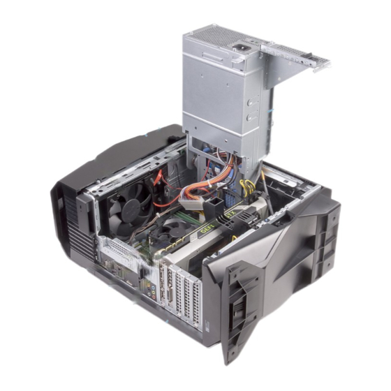
Inside view of your computer power-supply unit optical-drive assembly top cover top-chassis fan system board processor fan and heat-sink assembly graphics card right-side cover... -
Page 19: System-Board Components
System-board components top-chassis fan (TOP_FAN) processor-cooling assembly pump-fan connector (PUMP_FAN) processor-fan connector memory-module slot 1 (XMM1) (CPU_FAN) memory-module slot 2 (XMM2) memory-module slot 3 (XMM3) memory-module slot 4 (XMM4) front-chassis fan connector (FRONT_FAN) - Page 20 SATA 6 Gbps drive connector SATA 6 Gbps drive connector (SATA1) (SATA2) SATA 6 Gbps drive connector SATA 6 Gbps drive connector (SATA3) (SATA4) solid-state drive slot (M.2 SSD) CMOS reset jumper (CMOS JUMPER) Password reset jumper PCI-Express x16 mechanical/x8 (PASSWORD JUMPER) electrical slot (SLOT4) LED controller connector...
-
Page 21: Removing The Stability Foot
After working inside your computer. For more safety best practices, see the Regulatory Compliance home page at www.dell.com/regulatory_compliance. Procedure Place the computer on a clean and flat surface with the bottom cover facing Pull the securing tab to release the stability foot from the slots on the bottom... - Page 22 Lift the stability foot off the bottom cover. bottom cover stability foot security tab Lay the computer on its side.
-
Page 23: Replacing The Stability Foot
After working inside your computer. For more safety best practices, see the Regulatory Compliance home page at www.dell.com/regulatory_compliance. Procedure Place the computer on a clean and flat surface with the bottom cover facing Align the tabs on the stability foot with the slots on the bottom cover and snap the stability foot to lock it in place. -
Page 24: Removing The Left-Side Cover
After working inside your computer. For more safety best practices, see the Regulatory Compliance home page at www.dell.com/regulatory_compliance. Procedure NOTE: Ensure that you remove the security cable and security screw from the security-cable slot (if applicable). - Page 25 Release the left-side cover away from the chassis and then lift it from the computer. side-panel release latch top cover left-side cover...
-
Page 26: Replacing The Left-Side Cover
After working inside your computer, follow the instructions in After working inside your computer. For more safety best practices, see the Regulatory Compliance home page at www.dell.com/regulatory_compliance. Procedure Align the tabs on the left-side cover with the slots on the chassis. - Page 27 Snap the left-side cover to lock it in place. Figure 1. Replacing the left-side cover chassis slots tabs left-side cover...
-
Page 28: Removing The Right-Side Cover
Before working inside your computer. After working inside your computer, follow the instructions in After working inside your computer. For more safety best practices, see the Regulatory Compliance home page at www.dell.com/regulatory_compliance. -
Page 29: Procedure
Procedure Carefully pry around the edges of the right-side cover from the chassis. Figure 2. Removing the right-side cover chassis right-side cover Disconnect the lighting cable from the right-side cover. - Page 30 Lift the right-side cover off the chassis. Figure 3. Removing the right-side cover right-side cover lighting cable...
-
Page 31: Replacing The Right-Side Cover
Before working inside your computer. After working inside your computer, follow the instructions in After working inside your computer. For more safety best practices, see the Regulatory Compliance home page at www.dell.com/regulatory_compliance. -
Page 32: Procedure
Procedure Connect the lighting cable to the right-side cover. Figure 4. Connecting the lighting cable chassis lighting cable right-side cover tabs slots... - Page 33 Align the tabs on the right-side cover with the slots on the chassis and snap the right-side cover to lock it in place. Figure 5. Replacing the right-side cover chassis slots right-side cover...
-
Page 34: Removing The Top-Cover Assembly
Before working inside your computer. After working inside your computer, follow the instructions in After working inside your computer. For more safety best practices, see the Regulatory Compliance home page at www.dell.com/regulatory_compliance. Prerequisites Remove the left-side cover. Remove the right-side cover. - Page 35 Slide the lighting cable through the slot on the chassis. Figure 6. Removing the top cover lighting cable chassis screws (2) top cover Starting from the rear, release the tabs on the top cover from the slots on the chassis.
- Page 36 Lift the top cover off the chassis. Figure 7. Removing the top cover top cover slot lighting cable chassis...
- Page 37 Turn the top cover over, release the tabs on the top cover from the slots on the top bezel. Figure 8. Releasing the top cover from the top bezel...
- Page 38 Lift the top cover from the top bezel. Figure 9. Lifting the top cover from the top bezel top cover top bezel...
- Page 39 You are left with top bezel and top cover. Figure 10. Top cover and top bezel top bezel top cover...
-
Page 40: Replacing The Top-Cover Assembly
After working inside your computer. For more safety best practices, see the Regulatory Compliance home page at www.dell.com/regulatory_compliance. Procedure Align the tabs on the top cover with the slots on the top bezel and snap the top cover into place. -
Page 41: Removing The Bottom Cover
Before working inside your computer. After working inside your computer, follow the instructions in After working inside your computer. For more safety best practices, see the Regulatory Compliance home page at www.dell.com/regulatory_compliance. Prerequisites Remove the left-side cover. Remove the two 2.5-inch hard-drive cages. -
Page 42: Procedure
Procedure Press the securing tabs to release the bottom cover from the slots on the chassis. Figure 11. Releasing the bottom cover from the chassis securing tabs (8) slots (8) Tilt the computer towards the front until the base is facing up. - Page 43 Lift the bottom cover from the chassis. Figure 12. Removing the bottom cover Tilt the computer back to the upright position.
-
Page 44: Replacing The Bottom Cover
After working inside your computer. For more safety best practices, see the Regulatory Compliance home page at www.dell.com/regulatory_compliance. Procedure Tilt the computer towards the front until the base is facing up. Align the tabs on the bottom cover with the slots on the chassis and snap the bottom cover to lock it in place. -
Page 45: Removing The 3.5-Inch Hard Drive
Before working inside your computer. After working inside your computer, follow the instructions in After working inside your computer. For more safety best practices, see the Regulatory Compliance home page at www.dell.com/regulatory_compliance. Prerequisites Remove the left-side cover. Procedure... - Page 46 Press the release tabs on the hard-drive carrier and slide the hard-drive carrier out of the hard-drive cage. Figure 13. Removing the hard drive data cable power cable hard-drive cage release tabs hard-drive carrier Pry the hard-drive carrier to release the tabs on the carrier from the slots on the hard drive.
- Page 47 Lift the hard drive off the hard-drive carrier. NOTE: Note the orientation of the hard drive so that you can replace it correctly. Figure 14. Removing the hard drive from the hard-drive bracket hard drive hard-drive carrier tabs (4)
-
Page 48: Replacing The 3.5-Inch Hard Drive
After working inside your computer. For more safety best practices, see the Regulatory Compliance home page at www.dell.com/regulatory_compliance. Procedure Place the hard drive into the hard-drive carrier and align the tabs on the carrier with the slots on the hard drive. -
Page 49: Removing The 2.5-Inch Hard Drives
Before working inside your computer. After working inside your computer, follow the instructions in After working inside your computer. For more safety best practices, see the Regulatory Compliance home page at www.dell.com/regulatory_compliance. Prerequisites Remove the left-side cover. Procedure... - Page 50 Press the release tabs on the hard-drive carrier and slide the hard-drive carrier out of the hard-drive cage. Figure 15. Removing the hard drive data cable power cable hard-drive cage release tabs hard-drive carrier Pry the hard-drive carrier to release the tabs on the carrier from the slots on the hard drive.
- Page 51 Lift the hard drive off the hard-drive carrier. NOTE: Note the orientation of the hard drive so that you can replace it correctly. Figure 16. Removing the hard drive from the hard-drive carrier hard drive hard-drive carrier tabs (4)
-
Page 52: Replacing The 2.5-Inch Hard Drives
After working inside your computer. For more safety best practices, see the Regulatory Compliance home page at www.dell.com/regulatory_compliance. Procedure Place the hard drive into the hard-drive carrier and align the tabs on the carrier with the slots on the hard drive. -
Page 53: Removing The Hard-Drive Cage
After working inside your computer, follow the instructions in After working inside your computer. For more safety best practices, see the Regulatory Compliance home page at www.dell.com/regulatory_compliance. Procedure Remove the screws that secure the hard-drive cage to the chassis. -
Page 54: Prerequisites
Lift the hard-drive cage off the chassis. Figure 17. Removing hard-drive cage chassis #6-32x1/4'' screws (2) hard-drive cage Prerequisites Remove the left-side cover. Remove the 3.5-inch hard drive. -
Page 55: Replacing The Hard-Drive Cage
After working inside your computer. For more safety best practices, see the Regulatory Compliance home page at www.dell.com/regulatory_compliance. Procedure Insert the hard-drive cage into its slot on the chassis. Align the tabs on the cage with the tabs on the chassis. -
Page 56: Removing The Power-Supply Unit
Before working inside your computer. After working inside your computer, follow the instructions in After working inside your computer. For more safety best practices, see the Regulatory Compliance home page at www.dell.com/regulatory_compliance. Prerequisites Remove the left-side cover. Procedure NOTE: Note the routing of all cables as you remove them so that you can reroute them correctly after you replace the power supply. - Page 57 Slide the power-supply unit cage release latches towards the unlock position. Figure 18. Sliding the power-supply unit cage release latches power-supply unit chassis power-supply unit cage release cage latches (2)
- Page 58 Lift the power-supply unit cage while pressing and holding the graphics-card bracket. power-supply unit cage graphics-card bracket chassis...
- Page 59 Rotate the power-supply unit cage away from the chassis. power-supply unit Press the releasing clip on the power-cable connectors and disconnect the power cables from the graphics card. Disconnect the power cables from the optical drive and hard drives.
- Page 60 Disconnect the processor-power cable and system-board power cable from the system board. power-supply unit hard-drive power cable graphics-card power cables releasing clips (2) hard-drive power cable processor-power cable optical-drive power cable system-board power cable Rotate the power-supply unit cage towards the chassis until the unit snaps into place.
- Page 61 10 Lift the power-supply unit bracket off the power-supply unit cage. chassis screws (2) power-supply unit bracket power-supply unit 11 Remove the screws that secure the power-supply unit to the chassis.
- Page 62 12 Lift the power-supply unit, along with the cables, off the chassis. chassis power-supply unit screws (4)
-
Page 63: Replacing The Power-Supply Unit
After working inside your computer. For more safety best practices, see the Regulatory Compliance home page at www.dell.com/regulatory_compliance. Procedure Place the power supply on the chassis. Align the screw holes on the power-supply unit with the screw holes on the chassis. -
Page 64: Removing The Processor-Cooling Assembly
Before working inside your computer. After working inside your computer, follow the instructions in After working inside your computer. For more safety best practices, see the Regulatory Compliance home page at www.dell.com/regulatory_compliance. Prerequisites Remove the left-side cover. Remove the right-side cover. -
Page 65: Procedure
Procedure Remove the screws that secure the radiator and fan assembly to the radiator and fan cage. Figure 19. Removing the processor-cooling assembly screws (4) radiator and fan cage Follow the procedure from step 1 to step 4 in "Removing the power-supply unit". - Page 66 Lift the processor-cooling assembly along with the cables off the computer. Figure 20. Removing the processor-cooling assembly processor-cooling assembly processor-cooling assembly cables system board captive screws (4)
-
Page 67: Replacing The Processor-Cooling Assembly
After working inside your computer. For more safety best practices, see the Regulatory Compliance home page at www.dell.com/regulatory_compliance. Procedure Slide the radiator and fan assembly into the radiator and fan cage. Align the screw holes on the radiator and fan assembly with the screw holes on the radiator and fan cage. -
Page 68: Removing The Coin-Cell Battery
After working inside your computer. For more safety best practices, see the Regulatory Compliance home page at www.dell.com/regulatory_compliance. CAUTION: Removing the coin-cell battery resets the BIOS setup program’s settings to default. It is recommended that you note the BIOS setup program’s settings before removing the coin-cell battery. - Page 69 Lift the coin-cell battery out of its socket. Figure 21. Removing the coin-cell battery battery-release lever plastic scribe coin-cell battery coin-cell battery socket...
-
Page 70: Replacing The Coin-Cell Battery
After working inside your computer. For more safety best practices, see the Regulatory Compliance home page at www.dell.com/regulatory_compliance. Procedure Insert a new coin-cell battery (CR2032) into the battery socket with the positive side facing up, and snap the battery into place. -
Page 71: Removing The Memory Modules
Before working inside your computer. After working inside your computer, follow the instructions in After working inside your computer. For more safety best practices, see the Regulatory Compliance home page at www.dell.com/regulatory_compliance. Prerequisites Remove the left-side cover. Follow the procedure from step 1 to step 4 in "Removing the power-supply... - Page 72 Grasp the memory module near the securing clip, and then gently ease the memory module out of the memory-module slot. NOTE: Repeat step 2 to step 3 to remove any other memory modules installed in your computer. CAUTION: To prevent damage to the memory module, hold the memory module by the edges.
-
Page 73: Replacing The Memory Modules
After working inside your computer, follow the instructions in After working inside your computer. For more safety best practices, see the Regulatory Compliance home page at www.dell.com/regulatory_compliance. Procedure Ensure that the securing clips are extended away from the memory-module slot. - Page 74 Insert the memory module into the memory-module slot and press the memory module down until it snaps into position and the securing clips lock in place. Figure 23. Replacing the memory module memory module securing clips (2) memory-module slot system board NOTE: Use slots XMM1 and XMM2 if you need to use two memory modules.
-
Page 75: Post-Requisites
Post-requisites Follow the procedure from step 10 to step 11 in "Replacing the power-supply unit". Replace the left-side cover. -
Page 76: Removing The Solid-State Drive
After working inside your computer. For more safety best practices, see the Regulatory Compliance home page at www.dell.com/regulatory_compliance. CAUTION: Solid-state drives are fragile. Exercise care when handling the solid-state drive. CAUTION: To avoid data loss, do not remove the solid-state drive while the computer is in sleep or on state. - Page 77 Slide and lift the solid-state drive off the system board. solid-state drive screw solid-state drive slot system board...
-
Page 78: Replacing The Solid-State Drive
After working inside your computer, follow the instructions in After working inside your computer. For more safety best practices, see the Regulatory Compliance home page at www.dell.com/regulatory_compliance. CAUTION: Solid-state drives are fragile. Exercise care when handling the solid-state drive. Procedure Align the notch on the solid-state drive with the tab on the solid-state drive slot. -
Page 79: Post-Requisites
Press the other end of the solid-state drive down and replace the screw that secure the solid-state drive to the system board. solid-state drive notch screw solid-state drive slot system board Post-requisites Replace the graphics card. Follow the procedure from step 10 to step 11 in "Replacing the power-supply unit". -
Page 80: Removing The Graphics Card
Before working inside your computer. After working inside your computer, follow the instructions in After working inside your computer. For more safety best practices, see the Regulatory Compliance home page at www.dell.com/regulatory_compliance. Prerequisites Remove the left-side cover. Follow the procedure from step 1 to step 4 in "Removing the power-supply... -
Page 81: Procedure
Procedure Lift to release the graphics-card bracket from the chassis. Figure 24. Removing the graphics card graphics-card bracket graphics card Press the releasing clip on the power-cable connectors and disconnect the power cables from the graphics card. - Page 82 Push the securing tab on the PCIe slot away from the graphics card, grasp the card by its top corner, and ease it out of the slot. Figure 25. Removing the graphics card power cables releasing clips (2) graphics card securing tab...
-
Page 83: Replacing The Graphics Card
After working inside your computer. For more safety best practices, see the Regulatory Compliance home page at www.dell.com/regulatory_compliance. Procedure Align the graphics card with the slot on the system board. Place the card into the slot and press down firmly until the graphics card snaps into place. -
Page 84: Removing The Processor Fan And Heat-Sink Assembly
After working inside your computer. For more safety best practices, see the Regulatory Compliance home page at www.dell.com/regulatory_compliance. WARNING: The heat sink may become hot during normal operation. Allow sufficient time for the heat sink to cool before you touch it. - Page 85 Lift the processor fan and heat-sink assembly off the system board. Figure 26. Removing the heat sink assembly processor-fan cable captive screws (4) processor fan and heat-sink assembly...
-
Page 86: Replacing The Processor Fan And Heat-Sink Assembly
After working inside your computer. For more safety best practices, see the Regulatory Compliance home page at www.dell.com/regulatory_compliance. Procedure NOTE: The original thermal grease can be reused if the original processor and heat-sink assembly are reinstalled together. -
Page 87: Removing The Processor
Before working inside your computer. After working inside your computer, follow the instructions in After working inside your computer. For more safety best practices, see the Regulatory Compliance home page at www.dell.com/regulatory_compliance. Prerequisites Remove the left-side cover. Follow the procedure from step 1 to step 4 in "Removing the power-supply... - Page 88 Lift the processor off the processor socket. Figure 27. Removing the processor release lever alignment post processor cover processor socket processor...
-
Page 89: Replacing The Processor
After working inside your computer. For more safety best practices, see the Regulatory Compliance home page at www.dell.com/regulatory_compliance. CAUTION: If either the processor or the heat sink is replaced, use the thermal grease provided in the kit to ensure that thermal conductivity is achieved. -
Page 90: Post-Requisites
Pivot the release lever down and place it under the tab on the processor cover. Figure 28. Replacing the processor processor socket processor alignment post processor cover release lever Post-requisites Replace the processor fan and heat-sink assembly processor-cooling assembly (as applicable). Follow the procedure from step 10 to step 11 in "Replacing the power-supply unit". -
Page 91: Removing The Wireless Card
Before working inside your computer. After working inside your computer, follow the instructions in After working inside your computer. For more safety best practices, see the Regulatory Compliance home page at www.dell.com/regulatory_compliance. Prerequisites Remove the left-side cover. Follow the procedure from step 1 to step 4 in "Removing the power-supply... - Page 92 Slide and remove the wireless card from the wireless-card slot. Figure 29. Removing the wireless card wireless-card bracket screw antenna cables wireless-card slot wireless card...
-
Page 93: Replacing The Wireless Card
After working inside your computer, follow the instructions in After working inside your computer. For more safety best practices, see the Regulatory Compliance home page at www.dell.com/regulatory_compliance. Procedure CAUTION: To avoid damaging the wireless card, do not place any cables under it. -
Page 94: Post-Requisites
Replace the screw that secures the wireless card to the system board. Figure 30. Replacing the wireless card wireless card notch antenna cables screw wireless-card bracket Post-requisites Follow the procedure from step 10 to step 11 in "Replacing the power-supply unit". -
Page 95: Removing The Antenna
Before working inside your computer. After working inside your computer, follow the instructions in After working inside your computer. For more safety best practices, see the Regulatory Compliance home page at www.dell.com/regulatory_compliance. Prerequisites Remove the left-side cover. Remove the right-side cover. - Page 96 Push down the antenna cables towards the top of the computer through the cable-routing slot on the chassis. Figure 31. Removing the antenna cables antenna cables routing guides chassis Remove the antenna cables from the routing guides on the chassis.
- Page 97 Pry the antenna off the chassis. Figure 32. Removing the antenna cables antenna antenna cables routing guides...
-
Page 98: Replacing The Antenna
After working inside your computer. For more safety best practices, see the Regulatory Compliance home page at www.dell.com/regulatory_compliance. Procedure Adhere the antenna to the chassis. Route the antenna cables through the routing guides on the chassis and slide the cables through the cable-routing slot on the chassis. -
Page 99: Removing The Front-Chassis Fan
Before working inside your computer. After working inside your computer, follow the instructions in After working inside your computer. For more safety best practices, see the Regulatory Compliance home page at www.dell.com/regulatory_compliance. Prerequisites Remove the left-side cover. Follow the procedure from step 1 to step 4 in "Removing the power-supply... - Page 100 Slide and lift the chassis fan off the chassis. Figure 33. Removing the chassis fan front-chassis fan bracket front-chassis fan cable...
- Page 101 Spread apart the tabs on the front-chassis fan bracket and lift the front- chassis fan along with its cable off the bracket. Figure 34. Removing the chassis fan front-chassis fan cable front-chassis fan bracket front-chassis fan...
-
Page 102: Replacing The Front-Chassis Fan
After working inside your computer. For more safety best practices, see the Regulatory Compliance home page at www.dell.com/regulatory_compliance. Procedure Align the tabs on the front-chassis fan bracket with the front-chassis fan and press down on the fan until it snaps into position. -
Page 103: Removing The Top-Chassis Fan
Before working inside your computer. After working inside your computer, follow the instructions in After working inside your computer. For more safety best practices, see the Regulatory Compliance home page at www.dell.com/regulatory_compliance. Prerequisites Remove the left-side cover. Follow the procedure from step 1 to step 4 in "Removing the power-supply... - Page 104 Remove the top-chassis fan from the chassis. Figure 35. Removing the top-chassis fan chassis screw top-chassis fan top-chassis fan cable Remove the top-chassis fan cable from the routing guide on the top-chassis fan bracket. Push the rubber grommets through the holes at each corner of the fan to release top-chassis fan from the bracket.
- Page 105 Lift the top-chassis fan off the top-chassis fan bracket. Figure 36. Removing the top-chassis fan top-chassis fan cable routing guide rubber grommets (4) top-chassis fan bracket top-chassis fan...
-
Page 106: Replacing The Top-Chassis Fan
After working inside your computer, follow the instructions in After working inside your computer. For more safety best practices, see the Regulatory Compliance home page at www.dell.com/regulatory_compliance. Procedure Align the holes on the top-chassis fan with the holes on the top-chassis fan bracket. -
Page 107: Removing The Optical Drive
Before working inside your computer. After working inside your computer, follow the instructions in After working inside your computer. For more safety best practices, see the Regulatory Compliance home page at www.dell.com/regulatory_compliance. Prerequisites Remove the left-side cover. Follow the procedure from step 1 to step 4 in "Removing the power-supply... - Page 108 Pull the securing tab to release the optical-drive carrier from the chassis. Figure 37. Disconnecting the power and data cables optical-drive carrier optical drive securing tab power cable data cable...
- Page 109 Push to slide the optical-drive assembly out through the front of the computer. Figure 38. Removing the optical drive optical-drive assembly chassis...
- Page 110 Remove the screw that secures the optical-drive bracket to the optical drive. Figure 39. Removing the optical drive screw optical-drive bracket optical drive Gently pull and disconnect the optical-drive bezel from the optical drive. Figure 40. Removing the optical drive optical drive optical-drive bezel...
-
Page 111: Replacing The Optical Drive
After working inside your computer. For more safety best practices, see the Regulatory Compliance home page at www.dell.com/regulatory_compliance. Procedure Align and snap the optical-drive bezel to the optical drive. Align the screw hole on the optical-drive bracket with the screw hole on the optical drive. -
Page 112: Removing The Front Bezel
Before working inside your computer. After working inside your computer, follow the instructions in After working inside your computer. For more safety best practices, see the Regulatory Compliance home page at www.dell.com/regulatory_compliance. Prerequisites Remove the left-side cover. Remove the right-side cover. - Page 113 Grasp and release the front bezel tabs sequentially from the top, by moving them outward from the front panel. Figure 41. Removing the front bezel front bezel chassis tabs...
- Page 114 Rotate and pull the front bezel away from the front of the chassis to release the tabs on the front bezel from the slots on the front panel. Figure 42. Removing the front bezel chassis tabs front bezel...
-
Page 115: Replacing The Front Bezel
After working inside your computer. For more safety best practices, see the Regulatory Compliance home page at www.dell.com/regulatory_compliance. Procedure Align and insert the front bezel tabs into the front panel slots. Rotate the front bezel towards the chassis until the front bezel tabs snap into place. -
Page 116: Removing The Power-Button Board
Before working inside your computer. After working inside your computer, follow the instructions in After working inside your computer. For more safety best practices, see the Regulatory Compliance home page at www.dell.com/regulatory_compliance. Prerequisites Remove the left-side cover. Remove the right-side cover. - Page 117 Lift the power-button module off the top cover. Figure 43. Removing the power-button module top cover power-button module screws (2) routing guide power-button module cable Release the power-button board from under the tabs on the power-button board bracket.
- Page 118 Lift the power-button board along with the cable off the power-button board bracket. Figure 44. Removing the power-button module power-button board bracket power-button board tabs (4) power-button module cable...
-
Page 119: Replacing The Power-Button Board
After working inside your computer. For more safety best practices, see the Regulatory Compliance home page at www.dell.com/regulatory_compliance. Procedure Align and slide the power-button board on the power-button board bracket and snap it into place. -
Page 120: Removing The Rear Trim Cover
Before working inside your computer. After working inside your computer, follow the instructions in After working inside your computer. For more safety best practices, see the Regulatory Compliance home page at www.dell.com/regulatory_compliance. Prerequisites Remove the left-side cover. Remove the right-side cover. - Page 121 Using the tab, slide and remove the rear trim cover from the chassis. Figure 45. Removing the rear trim cover chassis rear trim cover...
-
Page 122: Replacing The Rear Trim Cover
After working inside your computer. For more safety best practices, see the Regulatory Compliance home page at www.dell.com/regulatory_compliance. Procedure Align the tabs on the rear trim cover with the slots on the chassis and snap the cover to lock it in place. -
Page 123: Removing The System Board
After working inside your computer. For more safety best practices, see the Regulatory Compliance home page at www.dell.com/regulatory_compliance. NOTE: Your computer’s Service Tag is stored in the system board. You must enter the Service Tag in the BIOS setup program after you replace the system board. -
Page 124: Procedure
Procedure NOTE: Note the routing of all cables as you remove them so that you can reroute them correctly after you replace the system board. For information on system board connectors, see "System-board components". - Page 125 Disconnect all the cables connected to the system-board assembly. Figure 46. Removing the system board Top panel USB cables SATA 6 Gbps drive cable (SSUSB) (SATA1) SATA 6 Gbps drive cable system board (SATA2) front-panel audio cable LED controller cable (F_AUDIO) (LED_CONTROLLER) graphics-card power cable...
- Page 126 Remove the screws that secure the system-board assembly to the chassis. Lift the system-board assembly out of the chassis. Figure 47. Removing the system board chassis system board screws (8)
-
Page 127: Replacing The System Board
After working inside your computer. For more safety best practices, see the Regulatory Compliance home page at www.dell.com/regulatory_compliance. NOTE: Your computer’s Service Tag is stored in the system board. You must enter the Service Tag in the BIOS setup program after you replace the system board. -
Page 128: Entering The Service Tag In The Bios Setup Program
Follow the procedure from step 10 to step 11 in "Replacing the power-supply unit". Replace the left-side cover. Entering the Service Tag in the BIOS setup program Turn on or restart your computer. Press F2 when the AlienHead logo is displayed to enter the BIOS setup program. -
Page 129: Bios Setup Program
BIOS setup program BIOS overview CAUTION: Unless you are an expert computer user, do not change the settings in the BIOS Setup program. Certain changes can make your computer work incorrectly. NOTE: Before you change BIOS Setup program, it is recommended that you write down the BIOS Setup program screen information for future reference. - Page 130 Table 4. System setup options—Main menu Main System Date Displays the current date in mm/dd/ yyyy format. System Time Displays the current time in hh:mm:ss format. BIOS Information BIOS Version Displays the BIOS version number. Product Information Product Name Displays the product name. Default: Alienware Aurora R5.
- Page 131 Table 5. System setup options—Advanced menu Advanced Advanced BIOS Features Intel SpeedStep Allows you to enable or disable Intel Speedstep Technology. Default: Enabled. NOTE: If enabled, the processor clock speed and core voltage are adjusted dynamically based on the processor load. Virtualization Allows you to enable or disable Intel Virtualization Technology feature for...
- Page 132 Advanced Wake Up by Integrated LAN Allow the computer to be powered on by special LAN signals. AC Recovery Sets what action the computer takes when power is restored. Deep Sleep Control Allows you to define the controls when Deep Sleep is enabled. USB Wake Support (S3) Allows you to enable the USB devices to wake the system from Standby.
- Page 133 Advanced processor flex ratio and voltage in the Customization mode. Computrace Allows you to enable or disable the Computrace service using the Absolute software. Core Ratio Limit Override Allows you to set the core ratio limit. Single Core Allows you to select single core or multiple cores.
- Page 134 Table 7. System setup options—Boot menu Boot Boot List Option Displays the available boot devices. File Browser Add Boot Option Allows you to set the boot path in the boot option list. File Browser Del Boot Option Allows you to delete the boot path in the boot option list.
-
Page 135: Clearing Forgotten Passwords
Before working inside your computer. After working inside your computer, follow the instructions in After working inside your computer. For more safety best practices, see the Regulatory Compliance home page at www.dell.com/regulatory_compliance. Prerequisites Remove the left-side cover. Follow the procedure from step 1 to step 4 in "Removing the power-supply... -
Page 136: Post-Requisites
Replace the jumper plug on pins 215. Figure 48. Clearing forgotten passwords jumper plug P215 Post-requisites Follow the procedure from step 10 to step 11 in "Replacing the power-supply unit". Replace the left-side cover. -
Page 137: Clearing Cmos Settings
Before working inside your computer. After working inside your computer, follow the instructions in After working inside your computer. For more safety best practices, see the Regulatory Compliance home page at www.dell.com/regulatory_compliance. Prerequisites Remove the left-side cover. Follow the procedure from step 1 to step 4 in "Removing the power-supply... -
Page 138: Post-Requisites
Connect the system-board power cable to the system board. Figure 49. Clearing CMOS settings jumper plug P217 P216 system board Post-requisites Follow the procedure from step 10 to step 11 in "Replacing the power-supply unit". Replace the left-side cover. -
Page 139: Flashing The Bios
You may need to flash (update) the BIOS when an update is available or when you replace the system board. To flash the BIOS: Turn on your computer. Go to www.dell.com/support. Click Product support, enter the Service Tag of your computer, and then click Submit. -
Page 140: Technology And Components
NOTE: The audio drivers are already installed when you receive your computer. Downloading the audio driver Turn on your computer. Go to www.dell.com/support. Click Product support, enter the Service Tag of your computer and then click Submit. NOTE: If you do not have the Service Tag, use the auto-detect feature or manually browse for your computer model. -
Page 141: Changing The Audio Settings
Before installation After installation Changing the audio settings On the taskbar, click the search box, and then type Dell Audio. Click Dell Audio and change the audio settings as required. Graphics Alienware Aurora R6 is shipped with the following graphics options: Table 10. -
Page 142: Downloading The Graphics Driver
Downloading the graphics driver Turn on your computer. Go to www.dell.com/support. Click Product support enter the Service Tag of your computer, and then click Submit. NOTE: If you do not have the Service Tag, use the auto-detect feature or manually browse for your computer model. -
Page 143: Rotating The Display
Click Apply. Rotating the display Right-click on your desktop. - Page 144 Select Graphics Options → Rotation and select from the listed options. The display can be also rotated by selecting Rotate Display under the Display menu in the NVIDIA Control Panel. For computers shipped with the AMD video card, the display can be rotated by selecting the required rotation on Rotate Desktop tab in the AMD Catalyst Control Center.
-
Page 145: Usb
The following table shows the USB ports available in Alienware Aurora R6. Table 11. USB ports and its location Ports Location USB 3.0 Two on the front side USB 3.0 with PowerShare Two on the front side USB 2.0 Six on the back panel USB 3.1 Type-C... -
Page 146: Enabling Or Disabling The Usb In Bios Setup Program
Click Device Manager. The Device Manager window is displayed. Expand System devices. Enabling or disabling the USB in BIOS setup program Turn on or restart your computer. Press F2 when the AlienHead logo is displayed on the screen to enter the BIOS setup program. -
Page 147: Wi-Fi
Wi-Fi Alienware Aurora R6 is shipped with Wi-Fi 802.11b/g/n or Wi-Fi 802.11ac. Turning on or off Wi-Fi NOTE: There is no physical switch to enable or disable Wi-Fi. It has to be done through computer settings. Swipe-in from the right edge of the display, or click the Action Center icon on the taskbar to access the Action Center. -
Page 148: Configuring The Wi-Fi
Click the Action Center icon on the taskbar to access the Action Center. Click Wi-Fi, and then click Go to settings. A list of available networks is displayed. Select your network and click Connect. NOTE: Type the network security key, if prompted. Bluetooth Alienware Aurora R6 is shipped with Bluetooth 4.1/Bluetooth 4.2. -
Page 149: Turning On Or Off Bluetooth
Turning on or off Bluetooth NOTE: There is no physical switch to enable or disable Bluetooth. It has to be done through the computer settings. Click the Action Center icon on the taskbar to access the Action Center. Click Bluetooth to turn Bluetooth on or off. Pairing the Bluetooth-enabled devices Turn on Bluetooth. -
Page 150: Removing The Bluetooth Device
Click Yes to confirm the passcodes on both the devices. Removing the Bluetooth device Click the Action Center icon on the taskbar to access the Action Center. Click Bluetooth, and then click Go to settings. Click the device you want to remove, and then click Remove device. Transferring files between devices using Bluetooth Click the Action Center icon on the taskbar to access the Action Center. -
Page 151: Hard Drive
Select your Bluetooth device. Click Send or receive files via Bluetooth. In the Bluetooth File Transfer window, click Send files, and then select the file you want to transfer. Hard drive The following table shows the hard-drive options available in Alienware Aurora Table 12. -
Page 152: Identifying The Hard Drive In Bios Setup Program
A list of hard drives is displayed on the Main tab. For more information, see System setup options. Chipset Alienware Aurora R6 is shipped with the Intel Z270 chipset. Downloading the chipset driver Turn on your computer. Go to www.dell.com/support. -
Page 153: Memory
Click Device Manager. The Device Manager window is displayed. Expand System devices. Memory Alienware Aurora R5 has four DIMM (RAM) slots, which are accessible by removing the left-side cover and rotating the power-supply unit. Your computer... -
Page 154: Checking The System Memory In Windows
System Assessment (PSA). NOTE: If the operating system logo appears, wait until you see the desktop. Turn off your computer and try again. Processors Alienware Aurora R6 is shipped with the following processor options: • Generation Intel Core i3 •... -
Page 155: Identifying The Processors In Windows
Identifying the processors in Windows On the taskbar, click the search box, and then type Device Manager. Click Device Manager. The Device Manager window is displayed. Expand Processors . Checking the processor usage in the task manager Right-click on the taskbar. Click Task Manager. -
Page 156: Operating System
Click Performance tab to display the processor performance details. Operating System Alienware Aurora R6 is shipped with the Windows 10 factory installation. Service Tag location The service tag is a unique alphanumeric identifier that allows Dell service technicians to identify the hardware components in your computer and access warranty information. -
Page 157: Intel Chipset Software Installation Utility
Intel Chipset Software Installation Utility In the Device Manager, check if the chipset driver is installed. Install the Intel chipset updates from www.dell.com/support. -
Page 158: Video Drivers
Video drivers In the Device Manager, check if the video driver is installed. Install the video driver update from www.dell.com/support. Intel Serial IO driver In the Device Manager, check if the Intel Serial IO driver is installed. Install the driver updates from www.dell.com/support. -
Page 159: Intel Trusted Execution Engine Interface
Intel Trusted Execution Engine Interface In the Device Manager, check if the Intel Trusted Execution Engine Interface driver is installed. Install the driver update from www.dell.com/support. -
Page 160: Intel Wireless-Ac 8260 Wi-Fi And Bluetooth Drivers
Intel Wireless-AC 8260 Wi-Fi and Bluetooth drivers In the Device Manager, check if the network card driver is installed. Install the driver updates from www.dell.com/support. -
Page 161: Bios Overview
In the Device Manager, check if the Bluetooth driver is installed. Install the driver updates from www.dell.com/support. BIOS overview The BIOS manages data flow between the computer's operating system and attached devices such as hard disk, video adapter, keyboard, mouse, and printer. - Page 162 • The F2=Setup prompt appears at the top-right corner of the screen during boot.
-
Page 163: System Diagnostic Lights
System diagnostic lights The computer POST (Power On Self Test) ensures that it meets the basic computer requirements and the hardware is working appropriately before the boot process begins. If the computer passes the POST, the computer continues to start in a normal mode. However, if the computer fails the POST, the computer emits a series of LED codes in amber color during the start-up. -
Page 164: Getting Help And Contacting Alienware
NOTE: Availability varies by country and product, and some services may not be available in your country. NOTE: If you do not have an active internet connection, you can find contact information on your purchase invoice, packing slip, bill, or Dell product catalog.