
Related Manuals for Dell Alienware Aurora R16


Summary of Contents for Dell Alienware Aurora R16
- Page 1 Alienware Aurora R16 Owner's Manual Regulatory Model: D30M Regulatory Type: D30M004 August 2023 Rev. A01...
- Page 2 WARNING: A WARNING indicates a potential for property damage, personal injury, or death. © 2023 Dell Inc. or its subsidiaries. All rights reserved. Dell Technologies, Dell, and other trademarks are trademarks of Dell Inc. or its subsidiaries. Other trademarks may be trademarks of their respective owners.
-
Page 3: Table Of Contents
Contents Chapter 1: Views of Alienware Aurora R16.................... 7 Front...................................... 7 Back.......................................8 Back panel.................................... 9 Service Tag...................................11 Chapter 2: Set up your computer......................12 Chapter 3: Specifications of Alienware Aurora R16................17 Dimensions and weight...............................17 Processor....................................17 Chipset....................................17 Operating system................................18 Memory....................................18 Ports and connectors................................ - Page 4 Removing the left-side cover............................36 Installing the left-side cover............................37 Right-side cover................................. 38 Removing the right-side cover............................. 38 Installing the right-side cover............................39 Front bezel ..................................40 Removing the front bezel.............................40 Installing the front bezel...............................42 Top cover.................................... 43 Removing the top cover............................... 43 Installing the top cover..............................
- Page 5 Deleting or changing an existing system setup password..................108 Clearing CMOS settings............................. 108 Clearing BIOS (System Setup) and System passwords..................... 109 Chapter 11: Troubleshooting.........................111 Dell SupportAssist Pre-boot System Performance Check diagnostics................111 Running the SupportAssist Pre-Boot System Performance Check................111 System-diagnostic lights..............................111 Recovering the operating system............................. 112 Wi-Fi power cycle................................
- Page 6 Chapter 12: Getting help and contacting Alienware................114...
-
Page 7: Chapter 1: Views Of Alienware Aurora R16
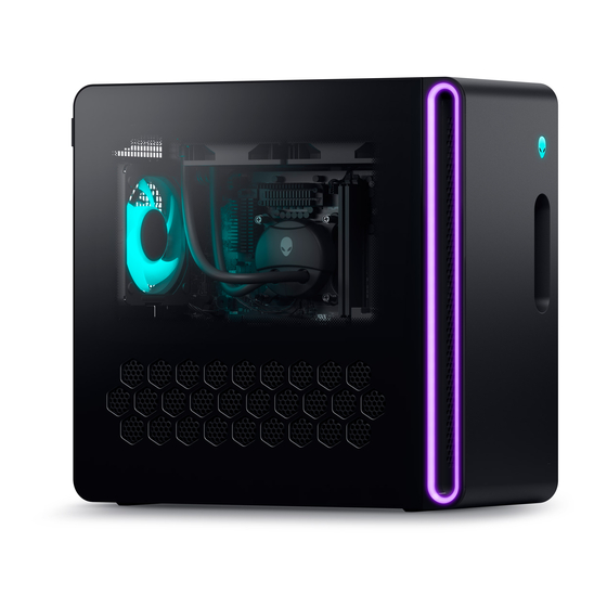
Views of Alienware Aurora R16 Front 1. Power button (Alien head) Press to turn on the computer if it is turned off, in sleep state, or in hibernate state. Press to put the computer in sleep state if it is turned on. -
Page 8: Back
NOTE: Deep Sleep is enabled by default. Disable Deep Sleep at the BIOS setup to enable PowerShare feature on your computer. NOTE: PowerShare enables you to charge your USB devices even when your computer is turned off. 5. USB 3.2 Gen 2 Type-C port with PowerShare Connect devices such as external storage devices and printers. -
Page 9: Back Panel
Connect a PCI-Express graphics card for optimal graphics performance. 10. Service Tag label The Service Tag is a unique alphanumeric identifier that enables Dell service technicians to identify the hardware components in your computer and access warranty information. 11. Back panel Connect USB, audio, video, and other devices. - Page 10 1. Hard-drive activity light The activity light turns on when the computer reads from or writes to the hard drive. 2. Optical S/PDIF port Connect an amplifier, speakers, or a TV for digital audio output through an optical cable. 3. Rear L/R surround port Connect audio-output devices such as speakers and amplifiers.
-
Page 11: Service Tag
Service Tag The service tag is a unique alphanumeric identifier that allows Dell service technicians to identify the hardware components in your computer and access warranty information. -
Page 12: Chapter 2: Set Up Your Computer
Set up your computer About this task NOTE: The images in this document may differ from your computer depending on the configuration you ordered. Steps 1. Connect the wired keyboard and mouse to suitable ports. To connect a wireless keyboard and mouse, see the instructions on how to connect in the documentation that ships with the wireless keyboard and mouse. - Page 13 Wireless network: This computer is shipped with an external puck antenna. Connect the external antenna during setup, to connect to WiFi and Bluetooth and improve the memory performance, while setting up your operating system. To connect the SMA cables, follow the below procedure: a.
- Page 14 Place the antenna in a suitable location.
- Page 15 3. Connect the display. For more information about setting up the display, see the documentation that is shipped with your display. NOTE: Connect the display to the discrete graphics card of your computer. 4. Connect the power cable to the computer and then connect it to the wall outlet.
- Page 16 5. Press the power button at the front of computer to turn on the computer.
-
Page 17: Chapter 3: Specifications Of Alienware Aurora R16
Specifications of Alienware Aurora R16 Dimensions and weight The following table lists the height, width, depth, and weight of your Alienware Aurora R16. Table 1. Dimensions and weight Description Values Height: Front height 418 mm (16.46 in.) Rear height 418 mm (16.46 in.) Width 197 mm (7.75 in.) -
Page 18: Operating System
● 64 GB, 2 x 32 GB, DDR5, 5200 MT/s, dual-channel NOTE: XMP memory support is currently unavailable. Ports and connectors The following table lists the external and internal ports available on your Alienware Aurora R16. Table 5. Ports and connectors Description... - Page 19 ● One M.2 2230 slot for WiFi and Bluetooth combo card ● Two M.2 2230/2280 card slots for solid-state drive NOTE: To learn more about the features of different types of M.2 cards, see the Knowledge Base resource at https:// www.dell.com/support.
-
Page 20: Ethernet
Killer E3100G Ethernet controller integrated on the system board Transfer rate 10/100/1000/2500 Mbps Wireless module The following table lists the Wireless Local Area Network (WLAN) modules that are supported on your Alienware Aurora R16. Table 7. Wireless module specifications Description Option one Option two... -
Page 21: Storage
PCIe Gen4 x4 NVMe, up to 64 Gbps Up to 4 TB 3.5-inch hard drive SATA AHCI 6 Gbps Up to 1 TB Power ratings The following table lists the power rating specifications of Alienware Aurora R16. Table 10. Power ratings Description Option one Option two Type... -
Page 22: Video
Option two Storage -40°C to 70°C (-40°F to 158°F) -40°C to 70°C (-40°F to 158°F) Video The following table lists the detailed discrete graphics specifications of your Alienware Aurora R16. Table 11. Discrete graphics specifications Discrete graphics Controller Number of... - Page 23 Table 12. Video port resolution (continued) Graphics card Video ports Maximum supported resolution ● 7680 x 4320 at 120 Hz ● 7680 x 4320 at 60 Hz ● 7680 x 4320 at 60 Hz ● 5120 x 3200 at 60 Hz ●...
-
Page 24: Operating And Storage Environment
Requires either a single DisplayPort 1.4a link with DSC compression or two DP links with no compression. Using DSC compression. Uncompressed. Operating and storage environment This table lists the operating and storage specifications of your Alienware Aurora R16. Airborne contaminant level: G1 as defined by ISA-S71.04-1985 Table 13. Computer environment Description... -
Page 25: Chapter 4: Working Inside Your Computer
CAUTION: You should only perform troubleshooting and repairs as authorized or directed by the Dell technical assistance team. Damage due to servicing that is not authorized by Dell is not covered by your warranty. See the safety instructions that is shipped with the product or at www.dell.com/regulatory_compliance. -
Page 26: Safety Precautions
Due to the increased density of semiconductors used in recent Dell products, the sensitivity to static damage is now higher than in previous Dell products. For this reason, some previously approved methods of handling parts are no longer applicable. -
Page 27: Esd Field Service Kit
It is recommended to use the traditional wired ESD grounding wrist strap and protective anti-static mat at all times when servicing Dell products. In addition, it is critical to keep sensitive parts separate from all insulator parts while performing service and that they... -
Page 28: Transporting Sensitive Components
Transporting sensitive components When transporting ESD sensitive components such as replacement parts or parts to be returned to Dell, it is critical to place these parts in anti-static bags for safe transport. After working inside your computer About this task CAUTION: Leaving stray or loose screws inside your computer may severely damage your computer. - Page 29 Table 14. Screw list (continued) Component Screw type Quantity Screw image Power-supply unit (for #6-32x1/4" computers shipped with clear left-side cover) Radiator and fan assembly for M3x5 liquid cooler Rear-chassis fan M3x5 Lower front-chassis fan M3x5 Solid-state drive (M.2 slot one/ M2x3 slot two) Wireless card...
-
Page 30: Major Components Of Alienware Aurora R16
Major components of Alienware Aurora R16 1. Front bezel 2. Left-side cover... - Page 31 3. Coin-cell battery 4. Wireless card 5. Liquid-cooling assembly (optional) 6. M.2 2280 solid-state drive 7. M.2 2230 solid-state drive (sold separately) 8. System board 9. Chassis 10. 3.5-inch hard drive 11. Power-supply unit 12. Power-supply unit bracket 13. VR heat sink 14.
-
Page 32: System-Board Components
System-board components 1. Coin-cell battery 2. Lower front-chassis fan connector (FAN_SYS2) 3. SATA 6 Gbps drive connector (HDD1) 4. SATA 6 Gbps drive connector (HDD2) 5. Power-supply connector (ATX1) 6. Solid-state drive slot (M.2 PCIe SSD-2) 7. Solid-state drive slot (M.2 PCIe SSD-1) 8. - Page 33 19. Power-supply connector (ATX3) 20.Power-supply connector (ATX2) 21. Air-cooling fan connector (FAN CPU) 22. Top-chassis fan connector two (FAN_SYS5) 23. SATA power connector (SATA PWR) 24.Wireless-card slot 25.Front I/O-panel cable...
-
Page 34: Chapter 5: Thermal Solution Matrix
Thermal solution matrix Table 15. Thermal solution matrix Processor Intel i7,i9 series non-K processors (65 Intel i7,i9 series non-K processors (65 Power supply 500 W 1000 W Graphics card power consumption Up to 225 W Up to 225 W Up to 225 Up to 400 Up to 400 Graphics card... -
Page 35: Chapter 6: Removing And Installing Customer Replaceable Units (Crus)
Removing and installing Customer Replaceable Units (CRUs) The replaceable components in this chapter are Customer Replaceable Units (CRUs). CAUTION: Customers can replace only the Customer Replaceable Units (CRUs) following the safety precautions and replacement procedures. NOTE: The images in this document may differ from your computer depending on the configuration you ordered. Antenna Removing the antenna Prerequisites... -
Page 36: Installing The Antenna
Installing the antenna About this task This computer is shipped with an external puck antenna. Connect the external antenna during setup, to connect to WiFi and Bluetooth and improve the memory performance. To connect the SMA cables, follow the below procedure. Steps 1. -
Page 37: Installing The Left-Side Cover
Steps 1. Loosen the captive screw (#6-32) that secures the side-cover release latch to the chassis. 2. Pull the side-cover release latch to release the left-side cover away from the chassis. 3. Lift the left-side panel from the chassis. Installing the left-side cover Prerequisites If you are replacing a component, remove the existing component before performing the installation procedure. -
Page 38: Right-Side Cover
Steps 1. Locate the tabs on the left-side cover and slots on the chassis. 2. Rotate the left-side cover towards the chassis until it snaps into place. 3. Tighten the captive screw (#6-32) that secures the side-cover release latch to the chassis. Next steps 1. -
Page 39: Installing The Right-Side Cover
Steps Pull and lift the right-side cover away from the chassis. Installing the right-side cover Prerequisites If you are replacing a component, remove the existing component before performing the installation procedure. About this task The following images indicate the location of the right-side cover and provide a visual representation of the installation procedure. -
Page 40: Front Bezel
Steps 1. Align the tabs on the right-side cover with the slots on the chassis. 2. Push the right-side cover towards the chassis until it snaps into place. Next steps 1. Install the left-side cover. 2. Follow the procedure in After working inside your computer. - Page 41 Steps 1. Place the computer in an upright position. 2. Disconnect the front I/O-panel cable from the system board. 3. Remove the four screws (#6-32x1/4") that secures the front bezel to the front panel. 4. Pull the tabs of the front bezel from the slots on the front panel. NOTE: Start with tab on top, proceed to the tabs on the left of the front bezel, and then to the tabs on the right of the front bezel.
-
Page 42: Installing The Front Bezel
Installing the front bezel Prerequisites If you are replacing a component, remove the existing component before performing the installation procedure. About this task The following images indicate the location of the front bezel and provide a visual representation of the installation procedure. Steps 1. -
Page 43: Top Cover
2. Route the front I/O-panel cable through the slot on the front panel. 3. Push the front bezel towards the front panel and ensure the tabs clip on to the slots of the front panel. NOTE: Start with tab on top, proceed to the tabs on the left of the front bezel, and then to the tabs on the right of the front bezel. -
Page 44: Installing The Top Cover
Steps Press down the latch from front side, and push/slide the cover toward to rear side, then lift the cover up. NOTE: The top cover is secured tight to the chassis by four latches. Installing the top cover Prerequisites If you are replacing a component, remove the existing component before performing the installation procedure. About this task The following images indicate the location of the top cover and provide a visual representation of the installation procedure. -
Page 45: 3.5-Inch Hard Drive
Steps Align the tabs on the top cover with the slots on the chassis and snap the top cover into place. Next steps 1. Install the front bezel. 2. Install the right-side cover. 3. Install the left-side cover. 4. Follow the procedure in After working inside your computer. - Page 46 About this task The following images indicate the location of the 3.5-inch hard drive and provide a visual representation of the removal procedure. Steps 1. Lay the computer on the right side. 2. Disconnect the data and power cables from the hard drive. 3.
-
Page 47: Installing The 3.5-Inch Hard Drive
NOTE: Note the orientation of the hard drive so that you can replace it correctly. Installing the 3.5-inch hard drive Prerequisites If you are replacing a component, remove the existing component before performing the installation procedure. About this task The following images indicate the location of the 3.5-inch hard drive and provide a visual representation of the installation procedure. - Page 48 Steps 1. Align the hard drive with the pins on the hard-drive carrier. 2. Using the tabs on the opposite side, flex open the carrier to insert the pins on the other side. 3. Slide the hard-drive assembly into the hard-drive cage until it snaps into place. 4.
-
Page 49: Identifying The Storage Device In Device Manager
(BIOS). NOTE: To install the operating system on to your storage device, see Reinstall Windows to the Dell factory image using recovery media in the Knowledge Base Resource at www.dell.com/support. Identifying the storage device in Device Manager Steps 1. -
Page 50: Installing The Coin-Cell Battery
Steps 1. Lay the computer on the right side. 2. Press the battery-release lever away from the coin-cell battery until the coin-cell battery pops up. 3. Lift the coin-cell battery out of its socket. Installing the coin-cell battery Prerequisites If you are replacing a component, remove the existing component before performing the installation procedure. About this task The following images indicate the location of the coin-cell battery and provide a visual representation of the installation procedure. -
Page 51: Memory Module
Steps Insert the new coin-cell battery (CR2032) into the battery socket with the positive side facing up, and snap the battery into place. Next steps 1. Install the left-side cover. 2. Follow the procedure in After working inside your computer. Memory module Removing the memory module Prerequisites... -
Page 52: Installing The Memory Module
Steps 1. Lay the computer on the right side. 2. Push the securing clips away from the memory module. 3. Lift the memory module off the memory-module slot. NOTE: Repeat step 2 to step 3 to remove any other memory modules installed in your computer. CAUTION: To prevent damage to the memory module, hold the memory module by the edges. -
Page 53: Single-Graphics Card
Steps 1. Ensure that the securing clips are extended away from the memory-module slot. 2. Align the notch on the memory module with the tab on the memory-module slot. 3. Insert the memory module into the memory-module slot and press the memory module down until it snaps into position and the securing clips lock in place. - Page 54 About this task The following images indicate the location of the single-graphics card and provide a visual representation of the removal procedure. Steps 1. Lay the computer on the right side. 2. Slide the release latch to its unlock position and lift the graphics-card end holder away from the PCIe fan. NOTE: Skip this step if your graphics card does not ship with a graphics-card end holder.
-
Page 55: Installing The Single-Graphics Card
4. Press the releasing clip on the graphics-card power connectors and disconnect the graphics-card power cables from the graphics card. 5. Lift the pull tab and open the expansion-card door. 6. Push the securing tab on the PCIe slot away from the graphics card, grasp the card by its top corner, and ease it out of the slot. Installing the single-graphics card Prerequisites If you are replacing a component, remove the existing component before performing the installation procedure. -
Page 56: Graphics-Card Bracket And Graphics-Card End Holder
After working inside your computer. Graphics-card bracket and graphics-card end holder The following table shows whether the graphics-card bracket or/and the graphics-card end holder is/are shipped with your Alienware Aurora R16. Table 17. Graphics-card bracket and graphics-card end holder Graphics card Graphics-card bracket... -
Page 57: Installing The M.2 2230 Solid-State Drive
Steps 1. Lay the computer on the right side. 2. Remove the screw (M2x3) that secures the M.2 2230 solid-state drive to the system board. 3. Slide and lift the M.2 2230 solid-state drive off solid-state drive slot one/slot two on the system board. Installing the M.2 2230 solid-state drive Prerequisites If you are replacing a component, remove the existing component before performing the installation procedure. -
Page 58: Removing The M.2 2280 Solid-State Drive
(BIOS). NOTE: To install the operating system on to your storage device, see Reinstall Windows to the Dell factory image using recovery media in the Knowledge Base Resource at www.dell.com/support. Removing the M.2 2280 solid-state drive Prerequisites 1. -
Page 59: Installing The M.2 2280 Solid-State Drive
Steps 1. Lay the computer on the right side. 2. Remove the screw (M2x3) that secures the M.2 2280 solid-state drive to the system board. 3. Slide and lift the M.2 2280 solid-state drive off SSD slot one/slot two on the system board. Installing the M.2 2280 solid-state drive Prerequisites If you are replacing a component, remove the existing component before performing the installation procedure. -
Page 60: Wireless Card
Identifying your storage device in system setup (BIOS). NOTE: To install the operating system on to your storage device, see Reinstall Windows to the Dell factory image using recovery media in the Knowledge Base Resource at www.dell.com/support. Wireless card Removing the wireless card Prerequisites 1. -
Page 61: Installing The Wireless Card
Steps 1. Lay the computer on the right side. 2. Remove the screw (M2x3) that secures the wireless card to the system board. 3. Lift the wireless-card bracket off the wireless card. 4. Disconnect the SMA cables from the wireless card. 5. -
Page 62: Lower Front-Chassis Fan
Steps 1. Connect the SMA cables to the wireless card. 2. Place the wireless-card bracket on the wireless card. 3. Align the notch on the wireless card with the tab on the wireless-card slot. 4. Slide the wireless card at an angle into the wireless-card slot. 5. - Page 63 About this task The following images indicate the location of the lower front-chassis fan and provide a visual representation of the removal procedure. Steps 1. Slide the release latch to its unlock position and lift the graphics-card end holder away from the PCIe fan. NOTE: Skip this step if your graphics card does not ship with a graphics-card end holder.
-
Page 64: Installing The Lower Front-Chassis Fan
5. Push the tab to release the lower front-chassis fan from the chassis. 6. Slide and lift the lower front-chassis fan off the chassis. Installing the lower front-chassis fan CAUTION: The information in this installation section is intended for authorized service technicians only. Prerequisites If you are replacing a component, remove the existing component before performing the installation procedure. - Page 65 Steps 1. Lay the computer on its right side. 2. Align the tabs on the lower front-chassis fan with the slots on the chassis. 3. Slide and push the fan until the releasing clip snaps into position on the chassis. 4.
-
Page 66: Rear-Chassis Fan
Next steps 1. Install the left-side cover. 2. Follow the procedure in After working inside your computer. Rear-chassis fan Removing the rear-chassis fan CAUTION: The information in this removal section is intended for authorized service technicians only. Prerequisites 1. Follow the procedure in Before working inside your computer. -
Page 67: Installing The Rear-Chassis Fan
Steps 1. Lay the computer on its right side. 2. Disconnect the rear-chassis fan cable from the system board. 3. Remove the screw (M3x5) that secures the rear-chassis fan to the chassis. 4. Slide and lift the rear-chassis off the chassis. Installing the rear-chassis fan CAUTION: The information in this installation section is intended for authorized service technicians only. -
Page 68: Top-Chassis Fan
2. Align the rear-chassis fan with the slot on the chassis. 3. Replace the screw (M3x5) that secures the rear-chassis fan to the chassis. 4. Connect the rear-chassis fan cable to the system board. Next steps 1. Install the left-side cover. -
Page 69: Installing The Top-Chassis Fan
Installing the top-chassis fan About this task The following images indicate the location of the top-chassis fan and provide a visual representation of the installation procedure. Steps 1. Lay the computer on the right side. 2. Align and place the top-chassis fan on the chassis. 3. -
Page 70: Chapter 7: Removing And Installing Field Replaceable Units (Frus)
CAUTION: To avoid any potential damage to the component or loss of data, ensure that an authorized service technician replaces the Field Replaceable Units (FRUs). CAUTION: Dell Technologies recommends that this set of repairs, if needed, to be conducted by trained technical repair specialists. - Page 71 Steps 1. Lay the computer on the right side.
-
Page 72: Installing The Power-Supply Unit
2. Disconnect the power-supply unit cables from the power-supply unit extension cables on the right side of the computer. 3. Note the cable routing when removing the power-supply unit cables through the slot on the right side of the computer. 4. - Page 73 Steps 1. Lay the computer on the right side. 2. Slide and place the power-supply unit on the chassis. 3. Align the screw holes on the power-supply unit with the screw holes on the chassis. 4. Replace the four screws (#6-32x1/4") that secure the power-supply unit to the chassis. 5.
-
Page 74: Processor Fan And Heat-Sink Assembly
Processor fan and heat-sink assembly Removing the processor fan and heat-sink assembly CAUTION: The information in this removal section is intended for authorized service technicians only. Prerequisites 1. Follow the procedure in Before working inside your computer. NOTE: The heat sink may become hot during normal operation. Allow sufficient time for the heat sink to cool before you touch it. -
Page 75: Installing The Processor Fan And Heat-Sink Assembly
4. Lift the processor fan and heat-sink assembly off the system board. Installing the processor fan and heat-sink assembly CAUTION: The information in this installation section is intended for authorized service technicians only. Prerequisites If you are replacing a component, remove the existing component before performing the installation procedure. CAUTION: If either the processor or the heat sink is replaced, use the thermal grease that is provided in the kit to ensure that thermal conductivity is achieved. -
Page 76: Processor Liquid-Cooling Assembly
2. Follow the procedure in After working inside your computer. Processor liquid-cooling assembly Removing the processor liquid-cooling assembly CAUTION: The information in this removal section is intended for authorized service technicians only. Prerequisites 1. Follow the procedure in Before working inside your computer. -
Page 77: Installing The Processor Liquid-Cooling Assembly
Steps 1. Lay the computer on the right side. 2. Remove the two screws (M3x5) that secures the radiator and fan assembly to the chassis. 3. Disconnect the radiator and fan assembly cable from the system board. 4. Disconnect the processor-cooling assembly cables from the system board. 5. - Page 78 About this task The following images indicate the location of the processor liquid-cooling assembly and provide a visual representation of the installation procedure. Steps 1. Align the screw hole of the radiator and fan assembly to the screw hole on the chassis and ensure that the spring latch is locked. NOTE: Ensure that the hoses are facing the front of the computer.
-
Page 79: Liquid-Cooling Assembly Fan
Liquid-cooling assembly fan Removing the liquid-cooling assembly fan CAUTION: The information in this removal section is intended for authorized service technicians only. Prerequisites 1. Follow the procedure in Before working inside your computer. 2. Remove the left-side cover. About this task The following images indicate the location of the liquid-cooling assembly fan and provide a visual representation of the removal procedure. -
Page 80: Installing The Liquid-Cooling Assembly Fan
Steps 1. Remove the four screws (#6-32x1/4") that secures the left liquid-cooling assembly fan to the liquid-cooling assembly. 2. Lift the left liquid-cooling assembly fan off the liquid-cooling assembly. 3. Remove the four screws (#6-32x1/4") that secures the right liquid-cooling assembly fan to the liquid-cooling assembly. 4. -
Page 81: Processor
Steps 1. Align and place the left liquid-cooling assembly fan on the liquid-cooling assembly. 2. Replace the four screws (#6-32x1/4") that secures the left liquid-cooling assembly fan to the liquid-cooling assembly. 3. Align and place the right liquid-cooling assembly fan off the liquid-cooling assembly. 4. -
Page 82: Installing The Processor
Steps 1. Press the release lever down and then push it away from the processor to release it from the tab. 2. Extend the release lever completely and open the processor cover. 3. Lift the processor off the processor socket. Installing the processor CAUTION: The information in this installation section is intended for authorized service technicians only. - Page 83 Steps 1. Ensure that the release lever on the processor socket is fully extended and the processor cover is fully open. CAUTION: Position the processor correctly in the processor socket to avoid permanent damage to the processor. 2. Align the pin-1 corner on the processor with the pin-1 corner on the processor socket, and then place the processor in the processor socket.
-
Page 84: Sma Cable
SMA cable Removing the SMA cable CAUTION: The information in this removal section is intended for authorized service technicians only. Prerequisites 1. Follow the procedure in Before working inside your computer. 2. Remove the left-side cover. 3. Remove the single-graphics card. - Page 85 Steps 1. Remove the washer and nuts that secure the SMA cable connector to the chassis. 2. Route the SMA cable assembly through the slot on the rear I/O. 3. Remove the SMA cable from the securing clip on the system board. 4.
-
Page 86: Installing The Sma Cable
Installing the SMA cable CAUTION: The information in this installation section is intended for authorized service technicians only. Prerequisites If you are replacing a component, remove the existing component before performing the installation procedure. About this task The following images indicate the location of the SMA cable and provide a visual representation of the installation procedure. -
Page 87: Vr Heat Sink
Steps 1. Align and place the SMA cable connector on the chassis. 2. Route the SMA cable under the PCIe x16 slot. 3. Insert the SMA cable to the securing clip on the system board. 4. Route the SMA cable assembly through the slot on the rear I/O. 5. - Page 88 NOTE: The VR heat sinks (2) are shipped as separate units and they do not ship along with the new system board. Remove the VR heat sink (2) from old system board for transfer to the new system board. 2. Remove the left-side cover.
-
Page 89: Installing The Vr Heat Sink
2. Loosen the captive screws that secure the VR heat sink to the system board. 3. Repeat the same process for the other VR heat sink. 4. Lift the VR heat sink (2) off the system board. Installing the VR heat sink CAUTION: The information in this installation section is intended for authorized service technicians only. -
Page 90: System Board
Steps 1. Align the captive screws of the VR heat sink with the screw holes on the system board. 2. Tighten the two captive screws that secure the VR heat sink to the system board. 3. Repeat the same procedure for the other VR heat sink. Next steps 1. - Page 91 5. Remove the memory module. 6. Remove the single-graphics card. 7. Remove the M.2 2230 solid-state drive or the M.2 2280 solid-state drive in SSD slot one or slot two, as applicable. 8. Remove the wireless card. 9. Remove the processor liquid-cooling assembly processor fan and heat-sink assembly, as applicable.
- Page 92 3. SATA 6 Gbps drive connector (HDD1) 4. SATA 6 Gbps drive connector (HDD2) 5. Power-supply connector (ATX1) 6. Solid-state drive slot (M.2 PCIe SSD-2) 7. Solid-state drive slot (M.2 PCIe SSD-1) 8. Memory-module slot, DIMM1 9. Memory-module slot, DIMM2 10.
-
Page 93: Installing The System Board
Steps 1. Disconnect the hard-drive data cables from the system board. 2. Disconnect the processor-power cables from the system board. 3. Disconnect the system-board power cables from the system board. 4. Disconnect the rear-chassis fan power cable from the system board. 5. - Page 94 About this task The following image indicates the connectors on your system board. 1. Coin-cell battery 2. Lower front-chassis fan connector (FAN_SYS2) 3. SATA 6 Gbps drive connector (HDD1) 4. SATA 6 Gbps drive connector (HDD2) 5. Power-supply connector (ATX1) 6.
- Page 95 19. Power-supply connector (ATX3) 20.Power-supply connector (ATX2) 21. Air-cooling fan connector (FAN CPU) 22. Top-chassis fan connector two (FAN_SYS5) 23. SATA power connector (SATA PWR) 24.Wireless-card slot 25.Front I/O-panel cable The following images indicate the location of the system board and provide a visual representation of the installation procedure.
- Page 96 Steps 1. Slide the front I/O-ports on the system board into the front I/O-slot on the chassis and align the screw holes on the system board with the standoffs on the chassis. 2. Place the system board on the standoffs on the chassis. 3.
- Page 97 7. Install the memory module. 8. Install the front bezel. 9. Install the right-side cover. 10. Install the left-side cover. 11. Follow the procedure in After working inside your computer.
-
Page 98: Chapter 8: Alienware Command Center
AlienFX, and game library. AWCC also supports Sound Management, Thermal Controls, CPU, GPU, Memory (RAM) monitoring. For more information about AWCC, see the Alienware Command Center Online Help or search in the Knowledge Base Resource at www.dell.com/support. -
Page 99: Chapter 9: Software
Your Alienware Aurora R16 supports the following operating systems: ● Windows 11 Pro, 64-bit ● Windows 11 Home, 64-bit Drivers and downloads When troubleshooting, downloading or installing drivers it is recommended that you read the Dell Knowledge Base article, Drivers and Downloads FAQs 000123347. -
Page 100: Chapter 10: Bios Setup
BIOS setup CAUTION: Unless you are an expert computer user, do not change the settings in the BIOS Setup program. Certain changes can make your computer work incorrectly. NOTE: Depending on the computer and its installed devices, the items listed in this section may or may not be displayed. NOTE: Before you change BIOS Setup program, it is recommended that you write down the BIOS Setup program screen information for future reference. -
Page 101: System Setup Options
Displays the current date in mm/dd/yy format. BIOS Version Displays the BIOS version number. Product Name Displays the product name. Default: Alienware Aurora R16 Service Tag Displays the service tag of your computer. Asset Tag Displays the asset tag of your computer. - Page 102 Table 20. System setup options—Advanced menu (continued) Advanced Default: All Multiple Atom cores Multiple Atom cores Allows you to configure Multiple Atom cores. Default: All Trusted Execution Trusted Execution Allows you to enable or disable Trusted Execution. Default: Disabled Integrated NIC Integrated NIC Allows you to enable or disable the integrated NIC.
- Page 103 NOTE: BIOS Auto-Recovery is not possible from other media. Default: Enabled SupportAssist System Resolution Controls the automatic boot flow for SupportAssist System Resolution Console and for Dell operating system Recovery tool.
- Page 104 Table 20. System setup options—Advanced menu (continued) Advanced Default: 2 Auto OS Recovery Threshold Allows you to configure the Auto OS Recovery Threshold. Default: 2 SupportAssist OS Recovery Allows you to enable or disable the SupportAssist OS Recovery. Default: Enabled Table 21. System setup options—Security menu Security Unlock Setup Status Displays the unlock setup status.
- Page 105 Table 21. System setup options—Security menu (continued) Security Secure Boot Enables secure boot using only validated boot software. Default: Disabled Secure Boot Mode Modifies the behavior of Secure Boot to allow evaluation or enforcement of UEFI driver signatures. Deployed Mode should be selected for normal operation of Secure Boot. Default: Deployed Mode Expert Key Management Custom Mode...
-
Page 106: Updating The Bios
Boot menu on the computer. Most of the Dell computers built after 2012 have this capability, and you can confirm by booting your computer to the F12 One Time Boot Menu to see if BIOS FLASH UPDATE is listed as a boot option for your computer. If the option is listed, then the BIOS supports... -
Page 107: System And Setup Password
● USB drive formatted to the FAT32 file system (key does not have to be bootable) ● BIOS executable file that you downloaded from the Dell Support website and copied to the root of the USB drive ● AC power adapter that is connected to the computer ●... -
Page 108: Deleting Or Changing An Existing System Setup Password
2. Select System/Admin Password and create a password in the Enter the new password field. Use the following guidelines to assign the system password: ● A password can have up to 32 characters. ● At least one special character: ! " # $ % & ' ( ) * + , - . / : ; < = > ? @ [ \ ] ^ _ ` { | } ●... -
Page 109: Clearing Bios (System Setup) And System Passwords
Steps 1. Turn off the computer and disconnect the power cable from the computer. 2. Remove the left-side cover. 3. Lay the computer on its right side. 4. Locate the 2-pin CMOS jumper on the system board. 5. Ensure that the jumper is on the pair of password pins (JM34). 6. - Page 110 Steps 1. Turn off the computer and disconnect the power cable from the computer. 2. Remove the left-side cover. 3. Lay the computer on its right side. 4. Locate the 2-pin password reset jumper on the system board. 5. Ensure that the jumper is on the pair of password pins (JM34) and remove the jumper. 6.
-
Page 111: Chapter 11: Troubleshooting
About this task SupportAssist diagnostics (also known as system diagnostics) performs a complete check of your hardware. The Dell SupportAssist Pre-boot System Performance Check diagnostics is embedded with the BIOS and is launched by the BIOS internally. The embedded system diagnostics provides a set of options for particular devices or device groups allowing you to: ●... -
Page 112: Recovering The Operating System
You can also download it from the Dell Support website to troubleshoot and fix your computer when it fails to boot into their primary operating system due to software or hardware failures. -
Page 113: Wi-Fi Power Cycle
3. Press and hold the power button for 20 seconds to drain the flea power. 4. Connect the power adapter to your computer. 5. Turn on your computer. NOTE: For more information about performing a hard reset, see the knowledge base article 000130881 www.dell.com/ support. - Page 114 Express Service Code. To view relevant support resources for documents. your Dell computer, enter the Service Tag or Express Service Code at www.dell.com/support. For more information on how to find the Service Tag for your...