
Related Manuals for Honeywell GNS-XLS


Summary of Contents for Honeywell GNS-XLS
- Page 1 GNS-X FLIGHT MANAGEMENT SYSTEM Operator’s Manual Global 006-08845-0000 Rev. 8 Apr/00...
- Page 2 ©1998, 2000 Honeywell International Inc. Reproduction of this publication or any portion thereof by any means without the express written permission of Honeywell International Inc. is prohibited. For further information contact the Manager, Technical Publications; Honeywell; One Technology Center; 23500 West 105th Street; Olathe,...
- Page 3 Revision 8, April, 2000 Part Number 006-08845-0000 This revision incorporates GNS-XLS Software Mod 6 and Mod 1 to AFIS DMU P/N 400-045500-0130 into Section 8, Regional Airlines AFIS Operation. Insert the contents of this revision packet according to the following...
- Page 4 Revision History and Instructions Manual GNS-X Operator’s Manual Revision 7, February, 1999 Part Number 006- 08845-0000 This revision incorporates AFIS DMU P/N 400-045500-0130 into Section 8, Regional Airlines AFIS Operation. Insert the contents of this revision packet according to the following instructions: Cover Page Remove and Replace...
- Page 5 Revision History and Instructions Manual GNS-X Operator’s Manual Revision 6, July 1998 Part Number 006-08845-0000 This revision consists of the following: Add Waypoint Type Identifier (2-54, 3-40, 3-45, 3-48, 3-49, 3-62) Revise Procedure Turn (3-41, 3-42, 3-43, 3-44) Remove H Hot Key (3-57, 3-58, 3-61) Add Fuel Used Reset Function (ix, 2-48, 3-105, 3-106) Typographic/Administrative Corrections (Inside Front Cover, 2-1, 2-2, 3-1, 3-2, 3-39, 3-59, 3-60, Back Covers)
- Page 6 Revision History and Instructions Manual GNS-X Operator’s Manual Revision 5, September 1997 Part Number 006-08845-0000 This revision consists of the following: Add Company Routes (vi, 2-2, 3.36.1, 3-36.2, I-2) Add Dedicated DME Interface (2-57) Add Approach Note (3-36.3) Typographic/Administrative Corrections (Front Covers, 2-1, 2-4, 2-9, 2-10, 2-11, 2-12, 2-27, 2-28, 2-79, 3-1, 3-2, 3-3, 3-4, 3-42, 3-43, 7-12, 7-15, 7-20, 7-22, 7-54, 7-55, 7-56, 7-57, 7-58, 7-59, Back Covers) Rev.
-
Page 7: Table Of Contents
Table of Contents SECTION 1 DESCRIPTION ...........1-1 OVERVIEW . - Page 8 Table of Contents FLIGHT PLAN “X” 1/1 (Page 1 of 1) ......2-3 DEPARTURE Page .........2-5 ARRIVAL Page .
- Page 9 Table of Contents GPS SUBSECTION 2/3 (Page 2 of 3) ......2-29 GPS SUBSECTION 3/3 (Page 3 of 3) ......2-31 VERTICAL NAVIGATION SECTION (VNAV KEY) .
- Page 10 Table of Contents TUNE 3/4 (Page 3 of 4) NAV ....... .2-56 TUNE 4/4 (Page 4 of 4) XPDR/ADF .
- Page 11 Table of Contents PRE-DEPARTURE ..........3-1 POWER ON/OFF AND PARALLAX ADJUSTMENT .
- Page 12 Table of Contents EDITING A SID FROM ANY STORED FPL OR THE ACTIVE FPL PAGE . . .3-21 ERASING A SID FROM ANY STORED FPL OR THE ACTIVE FPL PAGE . .3-22 ADDING OR DELETING WAYPOINTS WITHIN A SID ....3-23 To Add a Waypoint .
- Page 13 Table of Contents Using Radar Vectors to FINAL APPROACH COURSE ....3-39 USING OWN NAVIGATION - NO DME ARC .....3-41 PROCEDURE TURN .
- Page 14 Table of Contents EXITING HOLDING PATTERN BY GOING DIRECT TO HOLDING FIX ..3-68 EXITING HOLDING PATTERN BY PERFORMING A LEG CHANGE ..3-68 VERTICAL NAVIGATION (VNAV) OPERATION - PRE-DEPARTURE ..3-71 SETTING CRUISE ALTITUDE, TRANSITION LEVEL, AND DEFAULT FLIGHT PATH ANGLE .
- Page 15 Table of Contents TUNING COMMS ..........3-89 TUNING NAVs .
- Page 16 Table of Contents PARALLEL COURSE ......... .3-114 MANUAL MAGNETIC VARIATION ENTRY .
- Page 17 Table of Contents OMEGA NAVIGATIONAL NETWORK ....... .4-1 SECTION 5 DATABASE UPDATE .
- Page 18 Table of Contents AFIS FLT PLAN Page 3 ........7-10 Operator Inputs .
- Page 19 Table of Contents ADVISORY: ..........7-24 SYSTEM OPERATION .
- Page 20 Table of Contents Continue Sending Message ........7-42 AFIS Messages Review .
- Page 21 Table of Contents AUTO to MAN or OFF Mode ....... . .7-58 Returning to AUTO .
- Page 22 Table of Contents SYSTEM OPERATION ..........8-13 Pre-Departure .
- Page 23 Table of Contents Weather Menu Page .........8-42 Dispatch Menu Page .
- Page 24 Table of Contents THIS PAGE INTENTIONALLY LEFT BLANK xviii Rev. 7 GNS-X Flight Management System Feb/99...
-
Page 25: Description
Description SECTION 1 DESCRIPTION OVERVIEW The GNS-X Flight Management System is an integrated system designed to give the pilot centralized control for the navigation sen- sors, computer based flight planning, fuel management, and radio management. The GNS-X has a full color flat panel LCD display, alpha-numeric and function keys, a Global Positioning Sensor (GPS), and a navigation data base. - Page 26 Description Reference System (IRS) has excellent short term characteristics while VLF/Omega has excellent long term stability. The internal GPS sensor has excellent overall characteristics and will usually be the dominant sensor during blending. However, when RAIM is available, the GPS sensor is the sole contributor to the composite position. NOTE: RAIM (Receiver Autonomous Integrity Monitoring) is a quali- ty factor used to determine the accuracy of the GPS position.
-
Page 27: General Terms
Description GENERAL TERMS FIELD: A line of information. CURSOR: Yellow rectangular box placed over a field to enter or change the information in that field. The cursor is nor- mally out of view unless brought into view by depressing the Line Select Keys on either side of the screen. When information is entered into a field and the ENTER Key is depressed, the cursor will move to the next enterable field or disappear from the screen when the last field is... -
Page 28: Controls And Indicators
Description CONTROLS AND INDICATORS VNAV AFIS PLAN TUNE Depress and release the ON HOLD Key to apply power to the sys- tem. There is a warm-up period of approximately 30 seconds. The display illumination will ini- tially be set at 75% of full bright. BACK Depressing the ON Key for ENTER... -
Page 29: Alpha Keys
Description Depressing the MSG Key will display the message page. The newest message will be indicated with a flashing asterisk to the left of the message. If the message requires some action be taken by the operator, the MSG annunciator will remain on steadily until the action is completed. -
Page 30: Back Key
Description BACK KEY: VNAV AFIS PLAN TUNE HOLD The BACK Key is used to erase errors and page back- ward when the cursor is not dis- played. It can also be used to change data in a field if the cur- sor is present. -
Page 31: Previous (Prv) Key
Description PREVIOUS (PRV) KEY: VNAV AFIS PLAN TUNE The PRV Key is used to display HOLD the previous page of a section or subsection. This key also allows the operator to remain in a section or subsection by loop- ing from the first to the last and BACK back to the first page of that ENTER... -
Page 32: Colors
Description COLORS: The CDU displays are color coded to assist the operator in recogniz- ing information. The following is a list of these colors and their mean- ings: Magenta Lateral TO Waypoint, Vertical TO Waypoint, and TO Waypoint Yellow FROM Waypoint Caution Messages Data entered, but not yet accepted by the computer. -
Page 33: Page Display Definitions
SELF TEST PAGE SELF TEST For the first 30 seconds after GLOBAL the system if is turned on, the computer performs extensive HONEYWELL internal tests that must be INTERNATIONAL INC. successfully completed before proceeding further. If COPYRIGHT 2000... -
Page 34: Flight Plan Section (Fpl Key)
Page Display Definitions IDENT: Displays the airport identifier for the airport closest to the system shut down position. Dashes will be displayed when the cursor is placed over the position (POS) field. POS: Displays the last system position at shut down. Dashes are dis- played when the cursor is over the IDENT field. -
Page 35: Flight Plan "X
Page Display Definitions There are seven pages pos- FLIGHT PLAN LIST 1/1 sible with a maximum of 56 flight plans stored in non- KABQ KMSY > volatile memory. Each KDAL KHPN stored flight plan's origin and KDAL KSFO > KHPN KORD destination points are listed KHPN... - Page 36 Page Display Definitions • HP (Holding Pattern): FLIGHT PLAN 6 2/2 Indicates a holding pattern is < RW34 programmed at a particular +++++ < waypoint. (Figure 2-5) ##### • PT (Procedure Turn): < Indicates a procedure turn is < DEPART XFILL programmed at a particular ARRIVE...
-
Page 37: Departure Page
Page Display Definitions APPROACH: Used to access the APPROACH Page to enter a non-precision approach. (Figure 2-5) XFILL: Used to transfer information between systems in a dual sys- tem installation. In a single system installation, this prompt will not be displayed. -
Page 38: Arrival Page
Page Display Definitions SID: The Standard Instrument Departure (SID) can be selected from a list made available by pressing the Line Select Key adjacent to the SID field. TRANSITION: The Transition waypoint can be selected from a list made available by pressing the Line Select Key adjacent to the TRANSITION field. -
Page 39: Approach Page
Page Display Definitions TRANSITION: The Transition waypoint may be prefilled or selected from a list made available by pressing the Line Select Key adjacent to the TRANSI- TION field. STAR: The Standard Terminal Arrival (STAR) can be selected from a list made available by pressing the Line Select Key adjacent to the STAR field. - Page 40 Page Display Definitions RUNWAY: APCH KLAX < < RUNWAY RW24R Approach runway prefills if TYPE only one runway is available, < TRANSITION LAHAB last waypoint on Flight Plan WPTS OF APPROACH: is a runway, or can be select- LAHAB RW24R ed from a list made available LAX16 +++++...
-
Page 41: Airway Page
Page Display Definitions • FCF : Indicates Final Approach Course Alignment Fix. • ++++++: Separates the missed approach procedure waypoint from the rest of the approach. When the approach is flown, the system will continue to provide guidance along the final approach course and beyond the MAP until the pilot manually sequences to the missed approach way- point by using a DIRECT TO or HEADING mode procedure. -
Page 42: Active Fpl (Flight Plan)Page
Page Display Definitions ACTIVE FPL (Flight Plan)Page ACTIVE FPL FR MEM Current FROM waypoint. TO BWG 205 11 May also display DIRECT, < PSEUDO VORTAC, DME ------ < ARC, PROCEDURE KDAL -CMK TURN. (Figure 2-13) < KHART DEPART < < ARRIVE Current waypoint. - Page 43 Page Display Definitions DEPART: Same as stored Flight Plan Page. ARRIVE: Same as stored Flight Plan Page. APPROACH: Same as stored Flight Plan Page. ETA: (ETE/DIS/ALT) Estimated Time of Arrival at ACTIVE FPL DIRECT each waypoint on the Active TO KHART 19:37 Flight Plan based on current 19DFW...
- Page 44 Page Display Definitions NOTE: No database altitude constraints will be displayed at the MAP if the MAP is abeam or beyond the runway threshold . No altitude constraints are displayed on an approach if a PT is part of the approach procedure.
-
Page 45: Navigation Section (Nav Key)
Page Display Definitions NAVIGATION SECTION (NAV KEY) Upon pressing the NAV Key the NAVIGATION 1/4 Page will be dis- played and the following can be observed. NAVIGATION PAGES NOTE: If AFIS is installed in the system, the NAV section will consist of five pages. - Page 46 Page Display Definitions DIS: NAVIGATION 1/4 < FR 19DFW 20:28 The distance in nautical miles TO ELD 20:30 and tenths from the aircraft < < NX MEI 21:49 present position to the TO (42) waypoint. During Waypoint 00:00.6 Alert, the distance in whole (90) <...
- Page 47 Page Display Definitions NOTE: XFILL will not appear when DME ARC, ARC Intercept, Procedure Turn or Holding Pattern are in progress on the system performing the procedure. AUTO: The leg change mode. AUTO or MAN, may be selected if the cursor is over this field using the BACK Key.
- Page 48 Page Display Definitions • HP (Holding Pattern): Indicates a holding pattern is programmed at the TO waypoint. • PT (Procedure Turn): Indicates a procedure turn is programmed from the database at the TO waypoint. The airplane will fly the procedure turn. The next time over the PT waypoint, the system will sequence to the following way- point on the flight plan.
-
Page 49: Navigation
Page Display Definitions DIS: NAVIGATION 1/4 < < HOLD RIGHT AUTO The direct distance in nauti- AT MEI 20:41 cal miles and tenths from the < < EXIT HOLD 00:07.9 aircraft present position to the holding fix. (Figure 2-21) 00:07.9 INBOUND CRS ETE: WIND... - Page 50 Page Display Definitions WIND: NAVIGATION 2/4 < DIRECT 09:20 The first field displays head- AT D259J 09:44 wind/tailwind in knots with an < up arrow (↑) for tailwind or a WIND % 11 8& down arrow (↓) for headwind. ETA-RW11RC 09:54 The second field displays the FUEL-RW11RC...
-
Page 51: Navigation 3/4 (Page 3 Of 4)
Page Display Definitions SXTK: The selected crosstrack distance entered by the pilot to provide steering to an offset course parallel to the desired track (99.9 NM maximum). (Figure 2-22) NAVIGATION 3/4 (Page 3 of 4) Pressing the NAV Key again will display the third NAVIGATION Page and the following can be observed. -
Page 52: Navigation 4/4 (Page 4 Of 4)
Page Display Definitions HDG: The heading input received from an IRS or the aircraft compass sys- tem. If HDG can be manually inserted, MAN will be displayed. (Figure 2-23) BRG: The bearing in whole degrees from the aircraft present position to the TO waypoint. - Page 53 Page Display Definitions VLF SUBSECTION PAGES NOTE: The sensor SUBSECTION Pages may be accessed by plac- ing the cursor over the individual position sensor and pressing the ENTER Key. Use the NAV, PRV or NXT Key to page through the sensor SUBSECTION pages.
-
Page 54: Vlf Subsection
Page Display Definitions DR#: SUBSECTION The number of times the QUALITY VLF/Omega Sensor has been in DR since first enter- DR TIME: ing the VLF (primary) naviga- VLF‘ RCVD tion mode. This information USED OMEGA RCVD is not displayed if the system USED has never been in DR. - Page 55 Page Display Definitions VLF SUBSECTION 3/4 (Page 3 of 4) Pressing the NXT Key again will display the third VLF SUBSECTION Page and the following can be observed. Column 1: (Figure 2-27) VLF COMM Stations • WSH: Jim Creek, Washington •...
-
Page 56: Vlf Subsection
Page Display Definitions SPARE: The station is acquired and acceptable but is not needed for naviga- tion. DESELECT: The station has been manually deselected. CUTOUT: The station has been eliminated from use because its position deter- mining information is unacceptable. UNSTABLE: The station has sufficient amplitude for use but has not passed the stability test. -
Page 57: Irs/Ins Subsection Pages
Page Display Definitions Columns 2 and 3: Same as VLF SUBSECTION 3/4. IRS/INS SUBSECTION PAGES IRS (or INS) SUBSECTION 1/2 (Page 1 of 2) POS: The position in this field is SUBSECTION the same as POS on NAVI- GATION 4/4. (Figure 2-29) N 49 50.20 W111 41.60 IRS/INS:... -
Page 58: Vpu Subsection
Page Display Definitions VPU SUBSECTION PAGES Accessed through the NAVIGATION 4/4 Page (if AFIS is installed in the system, access is through the NAVIGATION 4/5 Page) by press- ing the Line Select Key corresponding to the VPU sensor, then pressing ENTER. VPU SUBSECTION 1/4 (Page 1 of 4) POS: SUBSECTION... - Page 59 Page Display Definitions NOTE: Entering 99 in this field will eliminate any previously entered value and no CHECK QUALITY message will appear. CURRENT MODE: Indicates the current mode of VPU navigation. The messages that can appear under it: (Figure 2-32) •...
-
Page 60: Vpu Subsection
Page Display Definitions VPU with Multiple Channel DME Inputs (Figure 2-34) NAV 1: SUBSECTION The stations received by the NAV 1 VOR/DME receivers. VPU STATIONS NAV 1 117.00 The station identifier is 83.4 shown adjacent to the field with the ACTIVE frequency. CH 2 113.70 10.6... -
Page 61: Gps Subsection
Page Display Definitions GPS SUBSECTION PAGES Accessed through the NAVIGATION 4/4 Page (if AFIS is installed in the system, access is through the NAVIGATION 4/5 Page) by press- ing the Line Select Key corresponding to the GPS sensor, then pressing ENTER. GPS SUBSECTION 1/3 SUBSECTION (Page 1 of 3) - Page 62 Page Display Definitions GPS TIME: GPS Time in hours, minutes and seconds. The advisory time is dis- played when at least one satellite is being tracked, other-wise the time field displays dashes. NOTE: GPS TIME may vary several seconds from GMT due to leap second input of UTC.
-
Page 63: Gps Subsection
Page Display Definitions RAIM/FDE?: Indicates RAIM and/or FDE is AVAILable or UNAVAILable. SATS TRACKED: Indicates the number satellites presently being tracked. GPS SUBSECTION 3/3 (Page 3 of 3) Pressing the NXT Key again SUBSECTION will display the third GPS SAT AZ EL SNR HLTH SUBSECTION Page and the... -
Page 64: Vertical Navigation Section (Vnav Key)
Page Display Definitions VERTICAL NAVIGATION SECTION (VNAV KEY) Upon pressing the VNAV Key the VNAV 1/3 Page will be displayed and the following can be observed. VNAV PAGES NOTE: AFIS flight plans do not support any altitudes, including air- port elevation. As a result no altitude constraints will be provided for SIDS, STARS or Approaches. - Page 65 Page Display Definitions • CLIMB: Indicates climb VNAV 1/3 required to cruise altitude or to < < CLIMB 5566 next altitude restriction. TO #TOC FL350 < < (Figure 2-38) RANGE (NM) 300.4 01:13.5 • CRUISE: Indicates holding altitude while enroute to Top ACTUAL FPM UP <...
- Page 66 Page Display Definitions • #TOD: Indicates the Top of Descent target altitude where the aircraft should begin its descent in order to arrive at the Descent Reference Waypoint at the required altitude. (Figure 2-39) NOTE: If no Descent Reference Waypoint with crossing altitude is pro- grammed, the system will use the arrival airport elevation to fix the #TOD as long as an airport is the last waypoint on the Active FPL.
- Page 67 Page Display Definitions DATA: A prompt to access the VNAV DATA Page, by placing the cursor over the DATA field and pressing the ENTER Key. (Figure 2-40) Figures 2-41 and 2-42 further illustrate the meanings of the fields on VNAV Page 1. VNAV 1/3 VNAV 1/3 <...
- Page 68 Page Display Definitions VNAV 1/3 < < CLIMB 15276 TO #TOC FL250 < < RANGE (NM) 33.5 00:13.2 ACTUAL CLIMB CLIMB GRAD 233 /NM < DATA Cruise Altitude =FL250 #TOC Vertical Last Departure altitude Speed constraint waypoint Groundspeed #TOC Range NOTE: Top of Climb appears as a Vertical Waypoint on the VNAV FPL Page when the aircraft is within 1 NM of...
-
Page 69: Vnav 2/3 (Page 2 Of 3) - Flight Plan Waypoint
Page Display Definitions VNAV 2/3 (Page 2 of 3) - FLIGHT PLAN WayPoint Pressing the VNAV Key will display the second VNAV Page and the following can be observed. VNAV MODE: Mode required to fly to the vertical TO waypoint and Baro Altitude in feet. -
Page 70: Vnav Data
Page Display Definitions • #PRESL: Indicates the estimated position where the aircraft will arrive at the altitude shown on the Altitude Pre-Selector. Field does not appear unless the system is configured for an altitude preselector and the aircraft is flying toward this altitude. (Figure 2-44) ++++++ :... - Page 71 Page Display Definitions The field also goes to dashes during a descent (digital systems only) when the aircraft is 200ft lower than the CRUISE ALT and the Preselect is set to a lower value. If the PRESEL is analog the altitude value will remain in the CRUISE ALT field.
-
Page 72: Vnav Waypoint
Page Display Definitions VNAV WAYPOINT 1/1 (Page 1 of 1) Accessed by placing the cursor over a lateral WPT and pressing the VNAV Key or by placing the cursor over a WPT in the VNAV section and pressing ENTER key. WAYPOINT: VNAV waypoint will consist of from one to six alphanumeric charac- ters. - Page 73 Page Display Definitions PLAN CROSSING: VNAV WAYPOINT 1/1 WAYPOINT VUZ System determined crossing FL180 based on programmed con- < EST CROSSING FL180 straints and flight path angles OFFSET for descent. (Figure 2-48) < REQ FPM This field is displayed for (AUTO) DN <...
-
Page 74: Afis Section (Afis Key)
Page Display Definitions • DEF: Indicates FPA default from VNAV DATA Page. NOTE: DIR, AUTO, and DEF can be accessed using the BACK Key. DIRECT FPA: Direct Flight Path Angle from the current aircraft altitude to the Vertical waypoint in degrees and tenths (valid range 0.0 to 90.0), where DN indicates negative FPA and UP indicates positive FPA. - Page 75 Page Display Definitions RESERVE: The desired reserve, as entered or verified by the operator, displayed in pounds or kilograms. This may require periodic verification or update. (Figure 2-50) FLOW: PLAN The current fuel flow in FUEL STATUS REMAINING 2990 pounds or kilograms input >...
-
Page 76: Plan 2/8 (Page 2 Of 8) Trip Plan
Page Display Definitions RANGE: The nautical mile range available until the reserve fuel quantity is reached. (Figure 2-50) Fuel flow and ground speed must be valid. NM/LB: The number of nautical miles for each pound (or kilogram) of fuel consumed. (Figure 2-50)Fuel flow and ground speed must be valid. - Page 77 Page Display Definitions DIS/DTK: The distance in nautical miles and tenths between either the FROM and TO waypoints or between the aircraft's present position and the TO waypoint. The desired track is the Great Circle course between the FROM and TO waypoints. The DTK will have a T adjacent to it if a true heading input is received or if the FROM waypoint is north N 70°...
-
Page 78: Plan 3/8 (Page 3 Of 8) Fuel Plan
Page Display Definitions PLAN 3/8 (Page 3 of 8) FUEL PLAN Pressing the FPL Key again will display the PLAN 3/8 Page. FUEL PLAN: The "A" indicates that Active PLAN < Flight Plan information is FUEL PLAN being displayed. A numeric DIRECT KDAL <... -
Page 79: Plan 4/8 (Page 4 Of 8) Fuel Flow
Page Display Definitions is based on the current fuel flow, groundspeed values and distance. (Figure 2-53) REM @: Appears only if a DIRECT TO leg is displayed. It indicates the amount of fuel remaining overhead at destination, or the last way- point on the Flight Plan that precedes a "fence", under current condi- tions. -
Page 80: Plan 6/8 (Page 6 Of 8) Aircraft Weight
Page Display Definitions TAKEOFF: PLAN The GMT at weight-off- DATE 18 FEB 95 wheels plus 10 seconds. < 14:13 (Figure 2-55) TAKEOFF 20:43 LAND: LAND 22:45 The GMT at weight-on- FLIGHT TIME 02+02 wheels. This field is not dis- played until weight-on-wheels plus 10 seconds occurs. -
Page 81: Plan 7/8 (Page 7 Of 8) Fde Prediction
Page Display Definitions VERIFY FUEL: This is displayed in the same field as VERIFY INPUTS if a manual fuel flow has been entered and has not been verified for 15 minutes or more. FUEL USED: If configured for Automatic Fuel Flow, the weight in pounds or kilo- grams of fuel consumed. - Page 82 Page Display Definitions EXPECTED GS: Estimated ground speed for the route segment. A value of 100 to 999 may be entered. START FDE WPT: First waypoint on the Oceanic/Remote route segment. Placing the cursor over this field allows waypoint entry. Pressing the BACK Key will cycle through the waypoints on the active flight plan.
-
Page 83: Fde Exclude Sats
Page Display Definitions • NEED ACTIVE FPL: This will be displayed if there are less than two waypoints on the active flight plan. • BACK FOR NEXT WPT: Displayed when the cursor is over the start or end waypoint field. •... - Page 84 Page Display Definitions When the FDE prediction is PLAN complete, the system will dis- FDE COMPUTATION play either FDE and NAV are available or unavailable. FDE AVAILABLE Normal calculation time is NAV AVAILABLE from ten to twenty minutes. See Figures 2-62 and 2-63. GPS PRIMARY MEANS NAV OK Figure 2-62...
-
Page 85: Heading Section (Hdg Key)
Page Display Definitions HEADING SECTION (HDG KEY) Upon pressing the HDG Key the HEADING VECTOR 1/1 Page will be displayed and the following can be observed. HEADING PAGE HEADING VECTOR 1/1 (Page 1 of 1) HDG: HEADING VECTOR 1/1 Commanded heading in whole degrees. - Page 86 Page Display Definitions TO WAYPOINT: Prefills with current TO Waypoint or is enterable (from one to six alphanumeric characters). (Figure 2-65) NOTE: With the cursor over the TO Waypoint field, using the BACK Key will step through to the end of the Active Flight Plan waypoints. The system will identify an IAF, ARC, PT, HP, FCF, FAF or MAP waypoint above the TO Waypoint field.
-
Page 87: Tuning Section (Tune Key)
Page Display Definitions TUNING SECTION (TUNE KEY) Upon pressing the TUNE Key the TUNE 1/4 Page will be displayed and the following can be observed. TUNING PAGES TUNE 1/4 (Page 1 of 4) COMM NOTE: If the system is configured for two or less communications radios, the tune section will display only three pages. -
Page 88: Tune 3/4 (Page 3 Of 4) Nav
Page Display Definitions TUNE 3/4 (Page 3 of 4) NAV Pressing the TUNE Key again will display this page and the following information may be observed. NAV 1 or NAV 2: The station identifier to which the respective NAV receiver is tuned. (KEY) will be displayed when the frequency or identifier of the station has been entered using the CDU keyboard. -
Page 89: Tune 4/4 (Page 4 Of 4) Xpdr/Adf
Page Display Definitions When dedicated TUNE 3/4 DM441B or the dedicated DME42 is configured, the DME 1 TUNE 3/4 page is different < FREQ 114.1 (Figure 2.67a). The Bearing RANGE information is suppressed and DME is annunciated DME 2 < FREQ 118.2 instead of NAV. -
Page 90: Holding Pattern Section (Hold Key)
Page Display Definitions HOLDING PATTERN SECTION (HOLD KEY) HOLDING PATTERN PAGE This page is accessed by depressing the HOLD Key when the cursor is positioned over a Waypoint Identifier. HOLDING PATTERN 1/1 (Page 1 of 1) HOLDING PATTERN The Holding Fix and country DILLY name or airport ident. - Page 91 Page Display Definitions Entry Course Outbound End Turn Point 70° Holding Course Outbound End Turn Point 70° Holding Course Entry Course Direct Entry Pattern Figure 2-70 Rev. 3 2-59 GNS-X Flight Management System Sep/96...
- Page 92 Page Display Definitions Turn Anticipation Holding Course Entry Course Direct to Holding Fix 70° Holding Course Entry Course 70° Teardrop Entry Pattern Figure 2-71 Rev. 3 2-60 GNS-X Flight Management System Sep/96...
- Page 93 Page Display Definitions Entry Course Go Direct to 110° Holding Fix Holding Course Leg Length Out Bound End Turn Point Note Path of 1st lap of holding pattern after entry procedure 110° Holding Course Parallel Entry Pattern Figure 2-72 Rev. 3 2-61 GNS-X Flight Management System...
- Page 94 Page Display Definitions • HOLDING: indicates the system has entered the Holding Pattern. (Figure 2-73) • EXIT HOLD: indicates the system will exit the holding pattern the next time over the holding fix. INBOUND CRS (course): HOLDING PATTERN The inbound holding course AT DILLY HOLDING in whole degrees.
-
Page 95: Position Fix Page
Page Display Definitions EXIT MODE: The MANUAL default indicates the system will stay in the holding pattern indefinitely. Using the BACK Key with the cursor over this field AUTO can be selected if the ENTER key is pressed. The system will then execute a holding pattern entry and exit the next time cross- ing the fix waypoint. -
Page 96: Direct To Section ( Key)
Page Display Definitions DIF: The difference between the composite position and the FIX (or other sensor) position in degrees, minutes and hundredths of minutes. (Figure 2-74) NOTE: Position coordinates of individual sensors and the difference between those sensor positions and the composite (system) position may be displayed by moving the cursor over the FIX field and depressing the BACK Key. -
Page 97: Waypoint Section
Page Display Definitions DIR CLOSEST ARP 2/2 DIR CLOSET ARP 1/2 (Page 2 of 2) < < 344/ 10 045/ 14 DIRECT TO CLOSEST AIR- < < 301/ 29 PORT: The Closest Airport KUNI 344/ 29 page is the last page in the <... -
Page 98: Database Wpt
Page Display Definitions VHF Navaids DATABASE WPT WAYPOINT: WAYPOINT Alphanumeric designator for N 3337.70 the Navaid. (Figure 2-77) W11609.60 FREQ 116.20 NOTE: If the waypoint has a E 13 duplicate identifier in the ELEV -110 database, for another loca- NDB-ENTER tion, the closest waypoint to the aircraft position will be Figure 2-77... - Page 99 Page Display Definitions Non-Directional Beacons (NDBs) NDBs stored in the internal DATABASE WPT 1/14 database are listed in Jeppesen publications with a WAYPOINT PRNB 2 or 3 letter identifier. To dis- tinguish these NDBs from N 54 15.80 VHF NAVAIDS, you must W130 25.40 add an "NB"...
- Page 100 Page Display Definitions • If the airport shows a 3 let- ter IDENTIFIER, add the cor- DATABASE WPT rect ICAO prefix letter. Example: (New WAYPOINT KNEW Orleans Lake Front) add a "K" prefix and enter KNEW N 30 02.60 W090 01.70 (Figure 2-81).
-
Page 101: Special Database Waypoints
Page Display Definitions Intersections/Enroute Waypoints Most intersection waypoint identifiers consist of 5 letters. However, 3, 4, and 5 letter and number combinations exist. To access these way- points, simply enter the identifier from the Jeppesen chart. Example: WHALE intersection. (Figure 2-84) DATABASE WPT SPECIAL DATABASE WAYPOINTS... -
Page 102: Offset Waypoint
Page Display Definitions WAYPOINT: PILOT ENTERED WPT (Figure 2-86). Same as pre- WAYPOINT GLOBAL vious. N 33 39.70 POS: W117 51.00 If the waypoint has been pre- viously defined, the coordi- nates of the waypoint will be 944 WPTS AVAIL displayed as stored in mem- ory. -
Page 103: Special Waypoints
Page Display Definitions When the waypoint has been previously defined the coordinates will be displayed and the radial and distance values will be computed based on the location of the parent waypoint. (Figure 2-87) If the parent waypoint is a waypoint from an airport continuation record (runway or outer marker associated with a specific airport), the airport identifier will be displayed immediately below the offset way- point identifier. -
Page 104: Power Off Waypoint
Page Display Definitions turn, #0 will be defined as the point at which the aircraft completes the turn and intercepts the direct course to the fix. #0 will momentarily be displayed on an EFIS map. #0 can only be defined by the system. #1 The position at the point where the POSITION FIX Page was last accessed via the HOLD Key. -
Page 105: Obsolete Waypoint
Page Display Definitions OBSOLETE WAYPOINT Obsolete Waypoints are typically created when a multiply defined database waypoint used on a stored flight plan is no longer found in the database. This may happen when a new data-base is loaded. An obsolete waypoint can be accessed only by verifying it as an existing waypoint on a flight plan. -
Page 106: System Messages
Page Display Definitions SYSTEM MESSAGES ACTION REQUIRED: The following are the action required messages that may appear on the SYSTEM MESSAGES Page. All will cause the message annun- ciator to flash. System Message Explanation ENTRY REQUIRED Information required on the Initialization Page must be verified/entered. -
Page 107: Advisory
Page Display Definitions ADVISORY: The following are the advisory messages that may appear on the SYSTEM MESSAGES Page. All will cause the message annuncia- tor to flash unless otherwise noted with an asterisk *. System Message Explanation ALTITUDE FAIL The altitude input to the system has failed. *APRCH ARMED Approach is ready to be executed. - Page 108 Page Display Definitions ADVISORY: (continued) System Message Explanation DR HDG/TAS The system is in the Dead Reckoning (DR) DR TK/TAS Mode and is using one of these four combi- DR TK/GS nations of inputs to compute position. DR HDG/GS EXT WPT REJECT CDU has rejected an external waypoint input from a radar or EFIS.
- Page 109 Page Display Definitions ADVISORY: (continued) System Message Explanation NO NAV The system is not navigating. Message annunciator will not illuminate. POS WARN>1.7 NM Based on the signal strength or geometry, the VPU sensor quality may be such that the composite position may have more than 1.7 nm error and may not be suitable for naviga- tion in the terminal areas.
-
Page 110: Sensor Messages
Page Display Definitions ADVISORY: (continued) *WPT ALERT The aircraft is within 30 seconds ETE of the next leg lateral change. Message annuncia- tor will not illuminate. WPT MEM FULL All 999 waypoint locations have been used in flight plans or as FROM or TO waypoints. VNAV WPT ALERT Aircraft is within 1 minute ETE of #TOD or path intercept point. - Page 111 Page Display Definitions SENSOR MESSAGES: (continued) Sensor Message Explanation Either the VLF (RPU), GPS or VPU sensor is in the Dead Reckoning (DR) mode of nav- igation. The message annunciator will not illuminate for VPU. ENTR SET HDG The IRS is in the attitude mode and a head- ing value must be entered.
- Page 112 Page Display Definitions THIS PAGE INTENTIONALLY LEFT BLANK Rev. 3 2-80 GNS-X Flight Management System Sep/96...
-
Page 113: System Operation
(momentarily). SELF TEST SELF TEST Page GLOBAL (Figure 3-1) will be dis- played for approximately HONEYWELL 30 seconds. During the INTERNATIONAL INC. time the SELF TEST message is displayed, the system is performing COPYRIGHT 2000 ALL RIGHTS RESERVED internal self tests. If the... -
Page 114: Initialization Page
System Operation INITIALIZATION PAGE INITIALIZATION It is important that the initial- DATE 01 JUN 00 ization position and the first > 18:42 waypoint of the Active Flight Plan are the same so that > IDENT KDAL the TO/FROM Leg Distance ---------- displays the correct informa- ----------... -
Page 115: Initialization Position
System Operation INITIALIZATION POSITION The Initialization Position for non-IRS equipped systems should be the departure runway threshold. For IRS equipped systems, the ramp or alignment LAT/LONG position should be inserted as Initialization Position. NOTE: Once the INITIALIZATION Page appears, and after a brief delay, the IDENT field normally prefills with the ICAO ident of the air- port closest to the aircraft position at shut-down, provided the air- craft’s real position and system position were the same at system... - Page 116 System Operation field, the departure air- DATABASE WPT port identifier will replace the ARP field, and POS WAYPOINT RW19R coordinates will reflect KSNA selected runway thresh- N 33 40.89 old. (Figure 3-4) W117 51.90 OM19R RW19R < > 4. ENTER Key - DEPRESS. RW01L RW01R <...
- Page 117 System Operation Option 2: Using the POS field For IRS equipped systems, the ramp or alignment LAT/LONG posi- tion should be inserted as the Initialization Position using POS Coordinates. Line Select Key - DEPRESS (cursor over POS field). POS Coordinates - VERIFY. Coordinates displayed are the computed position when the system was shutdown.
- Page 118 System Operation THIS PAGE INTENTIONALLY LEFT BLANK Rev. 3 GNS-X Flight Management System Sep/96...
-
Page 119: Building Flight Plans (Fpl)
System Operation BUILDING FLIGHT PLANS (FPL) CREATING A FLIGHT PLAN FPL Key - DEPRESS to display (Stored) FLIGHT PLAN LIST Page (if required). FLIGHT PLAN LIST 1/1 Line Select DEPRESS to position KABQ KMSY > cursor on blank line and KDAL KHPN KDAL... -
Page 120: To Delete A Waypoint
System Operation ENTER Key - DEPRESS to add waypoint to the FPL. Repeat Steps 4 through 7 for the remaining waypoints. The des- tination airport identifier should be the last waypoint on the flight plan. NOTE: Waypoints are generally obtained from the Navigation Data Base (NDB). -
Page 121: Deleting A Waypoint
System Operation depressing the FPL Key. Access a Stored Flight Plan from the alphabetized FLIGHT PLAN LIST Page. Use the PRV or NXT Keys to cycle through the available pages. NOTE: A change made to the Active Flight Plan does not affect the Stored Flight Plan. -
Page 122: Adding Oceanic Waypoints
System Operation identifier that will follow the FLIGHT PLAN new entry. (Figure 3-11) < KDAL - KHPN Type Waypoint Identifier - < INSERT. (Figure 3-12) < ENTER Key - DEPRESS. KHPN < > DEPART Waypoint Coordinates - ARRIVE SELECT VERIFY or INSERT. >... -
Page 123: Erasing A Stored Flight Plan
System Operation In the North Atlantic database, latitude entries may be made in one degree increments and longitude entries may be made in five degree increments. In the North Pacific database, latitude entries may be made in one degree increments and longitude entries may be made in ten degree increments. -
Page 124: Reviewing Waypoint Data/Coordinates (Flight Plan Pages Only)
System Operation waypoint nearest the air- DATABASE WPT craft position will be dis- played first. WAYPOINT PORTU To select an alternate way- N 38 45.60 point location: W027 05.60 FREQ 116.20 PRV or NXT Key - W 14 DEPRESS until desired ELEV country name is dis- NDB-ENTER... -
Page 125: Flight Plan (Fpl) Selection
System Operation FLIGHT PLAN (FPL) SELECTION This procedure is used to transfer a stored FPL to active FPL status. It is recommended that the initialization position and the first waypoint of the Active Flight Plan are the same so that the TO/FROM Leg Distance displays the correct information. -
Page 126: Initial Leg Selection
System Operation b. to INVERT and transfer FLIGHT PLAN the Stored Flight Plan < with waypoint sequence reversed to Active Flight < Plan status, press the KDTW < BACK Key to display ****** INVERT?. (Figure 3-17) < > DEPART ENTER Key - DEPRESS. ARRIVE INVERT? >... -
Page 127: Before Taxi (Irs Equipped)
System Operation Oceanic/Remote operation using GPS as the sole navigation source, an FDE prediction to determine sufficient GPS availability must be performed prior to departure. Refer to the Special Procedures sec- tion for instructions on performing the FDE prediction procedure. BEFORE TAXI (IRS EQUIPPED) The Inertial Reference System (IRS) should be aligned and placed in the Navigation Mode using the IRS manufacturer’s operating instruc-... -
Page 128: Sids, Stars, Approaches And Enroute Airways
System Operation MSG Key - DEPRESS. NAV RDY - HOLD/ENTER Message - VERIFY. This message indicates that the system is ready to enter the Primary Navigation Mode. MSG Key - DEPRESS to verify status of all sensors. Observe NAV RDY/NO NAV messages for appropriate sensor and refer to the Flight Manual Supplement for limitations. - Page 129 System Operation ELMAA 5 DEPARTURE SEATTLE 116.8 SEA This SID requires a mnimum climb gradiant of: Rwys 16 L/R: 550' per nm to 3000'. NAA7 26.1 W122 18.5 TAKE OFF Rwys 16L/R: intercept and proceed via Seattle R-158, cross Seattle 5 DME fix at or above 3000' then turn RIGHT to 250 heading to intercept SEATTLE-TACOMA and proceed via Seattle R-277 to Elmaa Int,...
-
Page 130: Entering A Sid On The Active Fpl
System Operation Due to the way the GNS-X database is structured, waypoints must have unique identifiers. However, some duplicate identifiers exist for more than one waypoint location. These waypoints are primarily located on APPROACHES, SIDS and STARS. In these cases the waypoint identifiers are renamed in the database as a 6 character identifier. - Page 131 System Operation If there are no SIDs associat- DEPARTURE KSEA ed with the Departure Airport, > RUNWAY ------ the message “NO SIDS ------ > AVAILABLE” appears and TRANSITION ------ the ident field flashes. BANGR1 < Depress the FPL Key to BLUTI1 ELMAA5? return to the Active Flight...
-
Page 132: Reviewing A Sid From Any Stored Fpl Or The Active Fpl Page
System Operation 9. Line Select DEPARTURE KSEA DEPRESS to position > RUNWAY RW16L cursor over the desired ELMAA3 runway. > TRANSITION WAYPOINTS OF SID: 10. ENTER Key - DEPRESS ELMAA to select RUNWAY. 11. Departure SID Waypoints > - REVIEW (Figure 3-26), SELECT? ERASE then... -
Page 133: Editing A Sid From Any Stored Fpl Or The Active Fpl Page
System Operation EDITING A SID FROM ANY STORED FPL OR THE ACTIVE FPL PAGE 1. Line Select DEPARTURE KSEA > DEPRESS to position RUNWAY RW16L cursor over the DEPART ------ > TRANSITION field on the FLIGHT ELMAA5? PLAN Page. 2. ENTER Key - DEPRESS. 3. -
Page 134: Erasing A Sid From Any Stored Fpl Or The Active Fpl Page
System Operation 6. ENTER Key - DEPRESS DEPARTURE KSEA to select desired TRAN- > RUNWAY RW16L SITION. The system will SUMMA5 automatically load the > TRANSITION compatible SID associat- WAYPOINTS OF SID: ed with the selected SUMMA TRANSITION. (Figure 3- >... -
Page 135: Adding Or Deleting Waypoints Within A Sid
System Operation ADDING OR DELETING WAYPOINTS WITHIN A SID NOTE: When a SID is modified by adding or deleting waypoints, the sequence of waypoints is no longer identified as a SID. To Add a Waypoint 1. Line Select ACTIVE FPL <... -
Page 136: Entering An Airway From Any Stored Fpl Or The Active Fpl Page
System Operation ENTERING AN AIRWAY FROM ANY STORED FPL OR THE ACTIVE FPL PAGE Enroute Airways include high altitude jet routes, low altitude and col- ored airways. 1. Line Select Key - DE- ACTIVE FPL PRESS to position cursor < KSEA - KLAX directly below the starting... -
Page 137: Option 2
System Operation c. Line Select Key - AIRWAY J501 DEPRESS to position < > RZS ? FR HQM cursor over the desired ZONAL HQM31 < > destination waypoint. (Figure 3-38). If applic- PESCA FINGS < > able, use PRV and ZESNB NIECE CAFTA... -
Page 138: Editing An Airway
System Operation NOTE: If the waypoint above the cursor is not a waypoint on the selected airway, the airway identifier will blink and the appropriate air- way or waypoint identifier must be entered. If the destination way- point is not on the airway, the system reverts to Option 1. d. -
Page 139: Entering A Star Or Profile Descent From Any Stored Fpl Or The Active Fpl Page
System Operation 3. ENTER Key - DEPRESS. AIRWAY J501 (Figure 3-42) > < FR HQM 4. Line Select < NIECE DEPRESS to move the cursor to shorten or < lengthen the previously ZONAL < selected segment of the RZS ? airway. - Page 140 System Operation If there are no STARs associated with the Arrival Airport, the mes- sage “NO STARS AVAILABLE” appears and the arrival airport ident field flashes. Depress FPL Key to return to ACTIVE FLIGHT PLAN. 4. NXT Key - DEPRESS to view waypoints on subsequent pages if desired.
-
Page 141: Reviewing A Star From A Stored Fpl Or The Active Fpl Page
System Operation 11. Arrival STAR Waypoints ARRIVAL KLAX - REVIEW (Figure 3-47), > RUNWAY ----- then DEPRESS ENTER TRANSITION Key to insert STAR into > STAR MOOR3 Active Flight Plan and WAYPOINTS OF STAR: return to the ACTIVE FLIGHT PLAN Page. DERBB PAULA REYES... -
Page 142: Erasing A Star From A Stored Fpl Or The Active Fpl Page
System Operation NOTE: A list will appear with other available STARs. Line Select Key - DEPRESS to position cursor over the desired STAR. ENTER Key - DEPRESS to select desired STAR. NOTE: Cursor moves to the first waypoint of the TRANSITION list and the TRANSITION field is displayed in yellow. -
Page 143: Adding Waypoints Within A Star
System Operation ADDING WAYPOINTS WITHIN A STAR NOTE: When a STAR is modified by adding or deleting waypoints, the sequence of waypoints is no longer identified as a STAR. The following may be accomplished from any stored flight plan or the ACTIVE FPL Page. -
Page 144: Entering An Approach On A Stored Fpl Or The Active Fpl Page
System Operation ENTERING AN APPROACH ON A STORED FPL OR THE ACTIVE FPL PAGE Line Select ACTIVE FPL DEPRESS to position cur- < KORD - KEWK sor over APPROACH? < field on the ACTIVE FPL page. (Figure 3-52) KEWK < ENTER Key - DEPRESS <... - Page 145 System Operation Enter Key - DEPRESS APPROACH KEWK select Approach > RUNWAY RW35 TYPE. (Figure 3-55) TYPE ------ > TRANSITION ------ NOTE: If there is only one NDB ? type of approach available < RNAV the system automatically loads the approach TYPE and the cursor moves over the WPT in the transition list.
-
Page 146: Reviewing An Approach From Astored Fpl Or The Active Fpl Page
System Operation 10. Approach Waypoints - APCH KEWK REVIEW (Figure 3-57), > RUNWAY RW35 then DEPRESS ENTER TYPE > Key to insert APPROACH TRANSITION WAIVE into Active Flight Plan and WPTS OF APPROACH: < return to the ACTIVE WAIVE RW17 CANB ++++++ FLIGHT PLAN Page. -
Page 147: Erasing An Approach From A Stored Fpl Or The Active Fpl
System Operation 1. Line Select Key (adjacent to RUNWAY field) - DEPRESS to change the field to dashes. 2. Line Select Key (adjacent to TYPE and TRANSITION fields) - DEPRESS to change the field to dashes. Using the same Line Select Keys, obtain a complete list of RUN- WAYS, TYPES, and TRANSITIONS. -
Page 148: Deleting An Approach Waypoint
System Operation DELETING AN APPROACH WAYPOINT Display the appropriate FPL Page. Line Select Key - DEPRESS to position cursor over the APPROACH waypoint identifier to be deleted. BACK Key - DEPRESS. A DELETE? prompt will appear adja- cent to the waypoint. ENTER Key - DEPRESS. -
Page 149: Selecting A Company Route And Adding It To The Active Flight Plan
System Operation SELECTING A COMPANY ROUTE AND ADDING IT TO THE ACTIVE FLIGHT PLAN Display the COMPANY ROUTES Page (automatically after ini- tialization, or by paging the FPL pages). NOTE: If the data base contains company routes, the first page dis- played after system initialization will be the COMPANY ROUTES page in lieu of the FLIGHT PLAN LIST page. - Page 150 System Operation NOTE: If the pair is not COMPANY ROUTES valid, COMPANY ROUTES page will remain, ORIGIN KCOF and a ROUTE NOT FOUND > DESTINATION KSMX message will be displayed. ------ > (Figure 3-59d) If the route is R#------ valid, but the Active FPL is <...
-
Page 151: Executing Approaches
System Operation EXECUTING APPROACHES Warning: When entering PTs or HP airspace at high speed the FMS may not constrain the airplane from violating maneuvering airspace. Pilots are responsible for procedural compliance. When the aircraft is within 30NM of the airport, the system will go into the Approach Armed mode. -
Page 152: Loading A Gps/Gps Overlay Approach
System Operation At the MAP the pilot must manually or via the HDG Mode maneuver the aircraft to the Missed Approach Procedure waypoint. If, after the missed approach, an approach at a different airport is desired, erase the current approach procedure before selecting a procedure at the new airport. -
Page 153: Executing A Gps/Gps Overlay Approach
System Operation 12. Approach Waypoints - REVIEW. 13. ENTER Key - DEPRESS ACTIVE FPL Page is displayed. VER- IFY the approach appears as selected. 14. Waypoint Sequencing - Edit, if required, based on assigned route. EXECUTING A GPS/GPS OVERLAY APPROACH NOTE: To fly a full procedure DME ARC or Procedure Turn, either coupled or using own navigation, follow the FMS and EFIS/Instrument displays. - Page 154 System Operation 8. ENTER Key - DEPRESS HEADING VECTOR 1/1 twice to engage Heading Select mode. (Figure 3- < HDG SELECT ? < After receiving the final TO DRK intercept vector from < > ATC: OK? ENTER 9. HDG Key - DEPRESS to display the HEADING Figure 3-64 VECTOR Page.
-
Page 155: Procedure Turn
System Operation USING OWN NAVIGATION - NO DME ARC 1. FPL Key - DEPRESS to ACTIVE FPL < display the ACTIVE FPL KEED - KPRC Page. (Figure 3-66) < 2. Approach and Waypoint KPRC < Sequencing - VERIFY they appear as selected. <... - Page 156 System Operation NOTE: When flying the approach on a transition that specifies NoPT and a “PT” waypoint is depicted on the flight plan, it will be necessary to do a DIRECT TO the next waypoint beyond the “PT” waypoint to avoid flying the Procedure Turn.
- Page 157 System Operation NAVIGATION 1/4 PROCEDURE TURN TO INTCPT ----- < > NX LEFT INTCPT (2.5) 12.9 00:04.8 > WIND ---/--- > Figure 3-70 NAVIGATION 1/4 PROCEDURE TURN TO INTCPT ----- > < NX LEFT INTCPT (5.2) 00:02.5 INBOUND CRS > WIND ---/--- >...
-
Page 158: Using Radar Vectors To Intercept A Dme Arc
System Operation NOTE: If aircraft is configured for dual systems no XFILL? prompt will be displayed during a PT even if dissimilar data exists in each system. Estimated Time Enroute (ETE) that is dispayed after crossing the IAF on the procedure turn is the time from the aircraft’s present position to where the airplane intercepts the final approach course inbound (INTCPT). -
Page 159: Waypoints And Hsi Course - Verify Proper Sequencing During The Approach
System Operation 6. HDG Key - DEPRESS to HEADING VECTOR 1/1 display the HEADING VECTOR Page. (Figure < 3-75) CANCEL 7. Heading - INSERT as assigned by ATC. TO DRK 8. ENTER Key - DEPRESS twice to engage HDG ENTER HDG SELECT mode. -
Page 160: Using Own Navigation To Fly Dme Arc
System Operation USING OWN NAVIGATION TO FLY DME ARC 1. FPL Key - DEPRESS to display the ACTIVE FPL Page. (Figure 3-77) ACTIVE FPL < KEED - KPRC 2. Approach and Waypoint Sequencing - VERIFY < they appear as selected. KPRC <... - Page 161 System Operation As the aircraft approaches NAVIGATION 1/4 the AR waypoint, a message < DIRECT 11:47 is displayed on the fourth line AR D259J 11:53 > < of the CDU indicating the NX DMEARC next action the aircraft will 00:001.0 take (NX DME ARC).
- Page 162 System Operation Use one of the following options to sequence to the missed approach waypoint. OPTION 1, Direct To the Missed Approach Procedure waypoint Key - DEPRESS. The DIRECT Page will be displayed. 2. Line Select Key - DEPRESS to position the cursor over the Missed Approach Procedure waypoint, if required.
-
Page 163: Navigation
System Operation ENTER Key - DEPRESS. HEADING VECTOR The cursor moves to the TO field. (Figure 3-85) L270 < BACK Key - DEPRESS INTERCEPT < until the Missed Approach Procedure waypoint is dis- MA12RC < > played. ENTER Key - DEPRESS. The cursor moves to the DTK field. - Page 164 System Operation THIS PAGE INTENTIONALLY LEFT BLANK Rev. 3 3-50 GNS-X Flight Management System Sep/96...
-
Page 165: Enroute
System Operation ENROUTE DIRECT TO - ACTIVE FLIGHT PLAN WAYPOINT function enables the pilot to fly direct to any lateral waypoint on the Active Flight Plan without reinserting the waypoint identifier. NOTE: If a Direct To the MAP on the active flight plan is initiated, the selected Approach Procedure will be canceled as indicated by the waypoints of the approach no longer being indented and a MSG. -
Page 166: Direct To - Hp Waypoint
System Operation DIRECT TO - HP WAYPOINT Key - DEPRESS. A DIRECT TO Page appears with the cursor over the current TO waypoint. 2. Line Select Key - DEPRESS to position the cursor over the desired HP identifier. (Figure 3-89) NOTE: Active Flight Plans DIRECT exceeding 18 waypoints will... -
Page 167: Direct To - Random Waypoint
System Operation DIRECT TO - RANDOM WAYPOINT This procedure enables the pilot to add a random waypoint to the ACTIVE FLIGHT PLAN in the desired sequence and proceed direct to it. Key - DEPRESS. The cursor will automatically appear over the current TO waypoint on the DIRECT TO Page. -
Page 168: Direct To - Closest Airport
System Operation A. Latitude - Insert N or S first, then degrees, minutes, and hun- dredths (6 characters) B. Longitude - Insert E or W first, then degrees, minutes, and hundredths (7 characters) If Direct To an offset waypoint is desired, the radial and distance entry from the parent waypoint may be required. -
Page 169: Pseudo-Vortac (Selected Course)
System Operation NOTE: The bearing and distance values to the closest airports are based on the aircraft’s present position at the time this page is accessed. The values are not updated while the page is being dis- played. To obtain updated information, it is necessary to exit the page then return. - Page 170 System Operation NOTE: The function may also be used to initiate a Pseudo- VORTAC. Following the Direct To entry using the Key the dis- play automatically advances to NAVIGATION Page 1. Manually position the cursor over DTK field and continue as described above in Steps 5 and 6.
-
Page 171: Using Heading Vector
System Operation USING HEADING VECTOR This procedure enables the pilot to program and fly a specific head- ing vector as well as program an automatic intercept of a specified leg. PROGRAMMING A HEAD- HEADING VECTOR 1/1 ING VECTOR 1. HDG Key - DEPRESS to <... -
Page 172: Changing Heading Vector While In Heading Select Mode
System Operation CHANGING HEADING VECTOR WHILE IN HEADING SELECT MODE HDG Key - DEPRESS to display HEADING VECTOR Page with cursor over the HDG field. Heading - INSERT desired Heading. ENTER Key - DEPRESS. NOTE: Cursor moves to the Heading Mode field, but it is not neces- sary to depress ENTER Key because the system is already in head- ing select mode.. -
Page 173: Canceling Heading Select Mode
System Operation 6. ENTER Key - DEPRESS. HEADING VECTOR 1/1 OK? ENTER message appears. (Figure 3-100) < 7. ENTER Key - DEPRESS HDG SELECT < to select TO Waypoint and return to NAVIGA- TO IAH < > TION Page 1. The cur- sor may be positioned OK? ENTER over the Leg Change... - Page 174 System Operation ENTER Key - DEPRESS. HEADING VECTOR 1/1 The cursor advances to Heading Mode field. < BACK Key - DEPRESS INTERCEPT ? to select INTERCEPT? < (Figure 3-101) TO LFK < > ENTER Key - DEPRESS. Cursor moves to the TO Waypoint field.
-
Page 175: Programming A Heading Intercept To The Final Approach Course
System Operation 9. ENTER Key - DEPRESS. HEADING VECTOR 1/1 An Intercept Message may appear (NO COURSE < INTERCEPT, NO ARC INTERCEPT, or INTER- INTERCEPT\ < CEPT BEYOND TO IAH (Figure 3-103). If no mes- < > INTERCEPT BEYOND FIX sage appears the intercept will occur on the TO side of OK? ENTER... - Page 176 System Operation BACK Key - DEPRESS to HEADING VECTOR 1/1 display the INTERCEPT? prompt. (Figure 3-105) < ENTER Key - DEPRESS. INTERCEPT ? The cursor moves to the < TO field. TO DRK < > BACK Key - DEPRESS until the FAF waypoint is OK? ENTER displayed.
-
Page 177: Programming A Holding Pattern
System Operation PROGRAMMING A HOLDING PATTERN Warning: When entering PTs or HP airspace the FMS may not constrain the airplane from violating maneuvering airspace. Pilots are responsible for procedural compliance. This procedure enables the pilot to program a Holding Pattern (HP) at a specific waypoint. - Page 178 System Operation When a Holding Procedure is initiated, the inbound course is dis- played on NAVIGATION Page 1. If the CDI needle does not auto- matically slew to the inbound course, manually set the CDI needle to the inbound course so that the course needle sensing is correct. A T adjacent to the value displayed in the INBOUND CRS field indi- cates the course is referenced to true north.
-
Page 179: Reviewing, Editing, Or Canceling A Holding Pattern
System Operation Selecting Exit Mode: 10. Line Select Key - DE- PRESS to position the HOLDING PATTERN cursor over MANUAL or AT TRM (USA) AUTO. Press the BACK DIRECT ENTRY > INBOUND CRS key to change exit mode MAX HOLDING TAS option. -
Page 180: Editing
System Operation EDITING 5. Line Select Key - DEPRESS to position cursor over desired field. a. INSERT value for INBOUND CRS, LEG TIME, or LEG DIST b. BACK Key - DEPRESS to change TURN DIR or EXIT MODE. 6. ENTER Key - DEPRESS. The OK? ENTER prompt will appear. NOTE: A re-entry to the Holding Pattern must be flown if the Inbound Course or Turn Direction are changed while holding at the HP Waypoint. -
Page 181: Exiting Holding Pattern Next Time Over Holding Fix
System Operation EXITING HOLDING PATTERN NEXT TIME OVER HOLDING FIX NAV Key - DEPRESS to NAVIGATION 1/4 display NAVIGATION < > HOLD RIGHT MANUAL Page 1, 2 or 3. AT ORD 01:01 < > EXIT HOLD 00:00.4 Line Select DEPRESS to position 00:00.4 the cursor over MANU- INBOUND CRS... -
Page 182: Exiting Holding Pattern By Going Direct To Holding Fix
System Operation EXITING HOLDING PATTERN BY GOING DIRECT TO HOLDING Key - DEPRESS to DIRECT < > display Direct To Page KABE with cursor over current > < HP Waypoint. (Figure 3- HASTE 115) < > KUBBS 2. ENTER Key - DEPRESS <... - Page 183 System Operation ENTER Key - DEPRESS. NAVIGATION 1/4 The next waypoint in the < > HASTE ------ Active Flight Plan 15:22 > < sequence will appear in EXIT HOLD 00:02 the TO field. (Figure 3- 00:02.4 118) INBOUND CRS TO Waypoint - VERIFY. WIND 375/ 13 To change the TO...
- Page 184 System Operation THIS PAGE INTENTIONALLY LEFT BLANK Rev. 3 3-70 GNS-X Flight Management System Sep/96...
-
Page 185: Vertical Navigation (Vnav) Operation - Pre-Departure
System Operation VERTICAL NAVIGATION (VNAV) OPERATION - PRE- DEPARTURE SETTING CRUISE ALTITUDE, TRANSITION LEVEL, AND DEFAULT FLIGHT PATH ANGLE This procedure allows the pilot to define a Cruise Altitude and change the default values for Transition Level and Flight Path Angle. After Initial Leg Selection: 1. -
Page 186: Creating/Changing Vnav Waypoints
System Operation NOTE: CRUISE ALT may also be inserted on VNAV Page 1, line 3 (adjacent to the TO waypoint field) when #TOC or #TOD are the TO waypoint. The cruise ALT may automatically be entered by the pres- elector if the preselector has the capability and the system is config- ured for digital preselector. - Page 187 System Operation After initial leg selection on NAV page 1: 1. NAV, FPL, or Key - DEPRESS to display applicable page. 2. Line Select Key - DEPRESS to position cursor over desired way- point. NOTE: On NAVIGATION Pages, only the TO Waypoint can be selected.
-
Page 188: To Program A Path Descent
System Operation b. Enter a (+), then the range value to indicate the offset is beyond the waypoint. c. To erase the offset value, INSERT 0 and press ENTER Key. The field changes to dashes, indicating no offset is pro- grammed. -
Page 189: Reviewing Vnav Waypoints
System Operation displayed on the CDU or the ADI/HSI. ENTER Key - DEPRESS to load or verify the FPA value. NOTE: When a descent FPA is programmed at a waypoint, a G appears next to the altitude constraint indicating a Glide Path and ver- tical deviation guidance and information will be available. -
Page 190: Using Vnav Flight Plan Waypoints Page
System Operation 6. Repeat Steps 2 through 5 to review VNAV waypoint data at remaining waypoints. Using VNAV Flight Plan Waypoints Page 1. VNAV Key - DEPRESS to display the VNAV FLIGHT PLAN WAYPOINTS Pages. 2. Line Select Key - DEPRESS to position the cursor over the desired waypoint. -
Page 191: Using Database (Db) Fpa
System Operation Using Database (DB) FPA The GNS-X database contains Flight Path Angles associated with waypoints on SIDs, STARs, and Approaches, that prefill when these procedures are programmed into the Active Flight Plan. The FPA field on the VNAV WAYPOINT Page displays (DB), which indicates an FPA from the database is loaded and Vertical Deviation is provid- ed at the programmed angle when the waypoint becomes the Vertical TO Waypoint. -
Page 192: Using Automatic (Auto) Fpa
System Operation Using Automatic (AUTO) FPA The (AUTO) mode is pro- WPT1 vided to link together 10000 descent waypoints that DESCENT PATH have Cross-At type con- straints and provide a com- puted Flight Path Angle WPT2 between them. (Figure 3- 5000 128) (AUTO) -
Page 193: Editing Altitude Constraints
System Operation EDITING ALTITUDE CONSTRAINTS The following pages allow the pilot to edit altitude constraints for way- points on the VNAV WAYPOINT Page, VNAV pages, referred to as VNAV FPL Pages. One of the three following options may be used: OPTION 1: Using the VNAV Page. -
Page 194: Option 3: Using The Vnav Waypoint Page
System Operation 3. Altitude Constraint - INSERT new altitude constraint followed by A (at or above) or B (at or below), if applicable. Any altitude value entered greater than the Transition Level value on the data page is converted and displayed as FL (flight level, rounded off to the near- est hundred feet). -
Page 195: Direct To - Vnav Waypoint As Lateral Waypoint
System Operation DIRECT TO - VNAV WAYPOINT AS LATERAL WAYPOINT This procedure enables the pilot to proceed Direct To a waypoint, both vertically and laterally by means of a Vertical Path Descent. If the current To waypoint is the desired VNAV Direct To waypoint, go to Step 4. 1. - Page 196 System Operation VNAV Key - DEPRESS to display the VNAV WAYPOINT Page for TO Waypoint. ALT - INSERT or VERIFY. If an altitude constraint has already been programmed, the cursor will be displayed over the FPA (DIR) field value. You may proceed to Step 10. (Figure 3-135) NOTE: If the waypoint is part of a SID, STAR or Approach proce- dure, the ALT constraint field prefills from the database.
-
Page 197: Direct To - Vnav Waypoint
System Operation 11. ENTER Key - DEPRESS to accept waypoint entries. VNAV Page 1 is displayed, a Vertical Path Descent has been estab- lished, and Vertical Deviation information and guidance is enabled if a descent has been programmed. DIRECT TO - VNAV WAYPOINT This procedure allows the DIRECT <... -
Page 198: Creating Vnav Profile Waypoints
System Operation 5. ENTER Key - DEPRESS. Cursor moves to OFFSET field. 6. OFFSET - If applicable, INSERT value in nautical miles (-99 to +99 range). a. If the offset is prior to the waypoint, enter the range value and a (-) prefills as a default or b. -
Page 199: Top Of Descent (#Tod)
System Operation When #TOC is the TO Waypoint: The pilot may obtain range and ETE to any altitude above the aircraft during a climb. VNAV Key - DEPRESS VNAV 1/3 > < to display VNAV Page 1. CLIMB 1775 TO #TOC 12000 Line Select... -
Page 200: Pre-Selected Altitude Intercept Point (#Presl)
System Operation One minute prior to arriving at #TOD, the system issues the VNAV WPT ALERT message and the discrete waypoint light will flash for 10 seconds, then go steady. NOTE: Changing CRUISE ALT on the CDU to a lower altitude should only be done after the aircraft has departed cruise altitude, or #TOD at the current cruise altitude will be lost. - Page 201 System Operation Cruise Altitude FL210 #TOD Vertical Constraint FL180B 16500 PLAN CROSSING CIVET 14000A Vertical Constraint Programmed FPA 8000 FUELR As shown, FUELR is the Descent Reference Waypoint Descent Reference that establishes #TOD. Because the programmed FPA allows for a vertical descent that meets the vertical constraints at CIVET, FUELR remains the KLAX Descent Reference Waypoint.
- Page 202 System Operation THIS PAGE INTENTIONALLY LEFT BLANK Rev. 3 3-88 GNS-X Flight Management System Sep/96...
-
Page 203: Remote Tuning
System Operation REMOTE TUNING TUNING COMMS This procedure enables the pilot to keyboard tune the aircraft radios via the CDU. Some control heads may require placement in the Remote Mode in order to accept tuning data from the CDU keyboard. NOTE: If system is configured for 3 Comms the tune section will con- sist of 4 pages. -
Page 204: Tuning Navs
System Operation The PRESET frequency displayed on the control head is not neces- sarily the PRESET frequency displayed on the CDU. Each may be entered independently. Depending on the system configuration the cursor can appear over the PRESET field for either COMM 1 or COMM 2. TUNE 2/3 TUNING NAVs NAV 1... - Page 205 System Operation NOTE: NAV tuning is designed to enhance the VPU (VORTAC Position Unit). The VPU will only use VOR/DME or DME only navaids (includes TACAN and ILS) therefore, only VOR/DME or DME only navaids will be displayed. In areas where a VOR only and a DME only are on the same frequency and within line of sight of the aircraft, entering the VOR identifier will result in the database replac- ing the VOR identifier with the “usable”...
-
Page 206: Auto Tune Method
System Operation When the station is locat- TUNE 2/3 ed in the VPU database the identifier will be dis- NAV 1 (KEY) > played and the (KEY) FREQ 115.50 annunciation will shift to RANGE 10.0 the identifier line. (Figure NAV 2 3-148) >... -
Page 207: Transponder And Adf Keyboard Tune
System Operation pause the CDU and con- TUNE 2/3 trol head information will change to reflect the NAV 1 > Identifier chosen by the FREQ 117.80 system. (Figure 3-151) RANGE 74.9 NOTE: No prompt is dis- NAV 2 > played adjacent to the FREQ (MAN) - Page 208 System Operation THIS PAGE INTENTIONALLY LEFT BLANK Rev. 3 3-94 GNS-X Flight Management System Sep/96...
-
Page 209: Planning Procedures
System Operation PLANNING PROCEDURES FUEL PLANNING PLAN Key - DEPRESS to display FUEL STATUS Page. NOTE: REMAINING and RESERVE quantities are stored in non- volatile memory after system shutdown. Upon system turn-on, VERIFY INPUTS is displayed and REMAINING, RESERVE, and FLOW values will flash. -
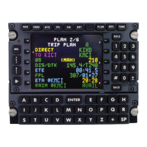
Page 210: Trip Planning
System Operation NOTE: HOURS of fuel and RANGE are calculated to the RESERVE fuel, not “0” fuel, unless the RESERVE fuel is “0”. To change the unit of measurement (LB or KG): Line Select Key - DEPRESS to position the cursor over the REMAINING field. - Page 211 System Operation 2. Line Select Key PLAN DEPRESS to position > TRIP PLAN the cursor over the TRIP DIRECT KDAL < PLAN field. TO LIT KHPN 3. Desired Flight Plan - > DIS/DTK -----/--- INSERT Flight Plan ------ Number (Figure 3-157) -----/----- or “A”...
-
Page 212: To Enter Manual Groundspeed
System Operation NOTE: With TRIP PLAN A PLAN selected, the TRIP PLAN leg > TRIP PLAN will automatically advance to DIRECT KDAL display DIRECT TO the cur- < KHPN rent NAVIGATION Page TO Waypoint each time the DIS/DTK -----/--- > ------ TRIP PLAN... - Page 213 System Operation 10. Data - CHECK. When DIRECT is displayed all data except DTK is updated continuously. If data is not continuously updated, it will be recalculated each time: The TRIP PLAN Page is selected. A TRIP PLAN is entered. A leg change is made on the TRIP PLAN Page.
-
Page 214: To Update The Trip Plan Leg To The Current To Waypoint With An Active Flight Plan Selected
System Operation To update the TRIP PLAN leg to the current TO waypoint with an Active Flight Plan selected: a. Line Select Key - DEPRESS to position cursor over TRIP PLAN field. b. ENTER the letter [A] in the cursor. c. - Page 215 System Operation DEPRESS to position PLAN the cursor over the > FUEL PLAN FUEL PLAN field. DIRECT KDAL < TO LIT KHPN 3. Desired Flight Plan - INSERT Flight Plan > FLOW 1200 Number (Figure 3-165) LEG FUEL ------ or “A” for Active Flight FPL FUEL ------ Plan.
-
Page 216: To Enter Manual Groundspeed
System Operation To Enter Manual Groundspeed: a. Line Select Key - DEPRESS to position cursor over GS value field. b. Groundspeed - INSERT. c. ENTER Key - DEPRESS. (MAN) will appear adjacent to the GS field. To Return To Automatic Groundspeed: a. - Page 217 System Operation b. The FUEL PLAN Page is selected. c. Leg or GS change is made on the FUEL PLAN Page. LEG FUEL and FPL FUEL are recalculated whenever the FLOW changes. d. FUEL FLOW is changed on FUEL STATUS Page. NOTE: The REM @ field only appears when a DIRECT TO leg is displayed.
-
Page 218: Verifying Or Changing Date And Time
System Operation The FUEL PLAN leg displays DIRECT TO the current NAVIGATION Page TO waypoint. Selecting another display page (other than MSG and TRIP PLAN) and returning to FUEL PLAN Page also updates the leg with DIRECT TO the current NAVIGATION Page TO waypoint. VERIFYING OR CHANGING DATE AND TIME DEPRESS the Plan Key until the DATE/GMT Page appears DATE:... -
Page 219: Verifying Or Changing Aircraft Weight Parameters
System Operation VERIFYING OR CHANGING AIRCRAFT WEIGHT PARAMETERS This procedure allows the pilot to confirm or adjust basic operating weight, payload, or fuel to current on board data. PLAN Key - DEPRESS to display AIRCRAFT WEIGHT Page NOTE: BASIC OP WT, PAYLOAD, and FUEL ON BOARD fields will be blinking if update has not been entered after system power up. -
Page 220: Resetting Fuel Used
System Operation RESETTING FUEL USED 1. PLAN Key - DEPRESS to display aircraft weight page. 2. Line Select Key - DEPRESS to place the cursor over FUEL USED. The field will display ZERO?. (Figure 3-172a) NOTE: To leave the FUEL USED field without changing the value, depress the line select key when the field displays ZERO?. -
Page 221: Special Procedures
System Operation SPECIAL PROCEDURES The following are various procedures that can be performed during navigation, when applicable. PILOT ENTERED LEG CHANGE NAV Key - DEPRESS to select NAVIGATION Page 1. A pilot entered leg change may be accomplished on any NAVIGATION Page with a FR/TO field. - Page 222 System Operation ENTER Key - DEPRESS. If Waypoint Page Appears: DATABASE WPT a. Waypoint Page Co- ordinates - VERIFY WAYPOINT CORLA Database Waypoint or INSERT Waypoint N 33 38.30 W116 16.70 Data. (Figure 3-174) Insert Waypoint Coordinates (cursor over NDB-ENTER POS Field): (1) Latitude - IN- Figure 3-174...
-
Page 223: Preventing Automatic Leg Changes
System Operation PREVENTING AUTOMATIC LEG CHANGES The Auto Leg change function allows the system to automatically sequence from waypoint to waypoint on the Active Flight Plan. When the system is initialized it is in the Automatic Leg Change Mode unless changed by the pilot. The following procedure inhibits auto- matic leg changes. -
Page 224: Dead Reckoning (Dr) To Primary Navigation Mode - Vlf (Rpu) Only Equipped
System Operation DEAD RECKONING (DR) TO PRIMARY NAVIGATION MODE - VLF (RPU) ONLY EQUIPPED NOTE: System automatically reverts to the Primary Navigation Mode 30 seconds after the NAV RDY-VERIFY POSITION message appears. VERIFY POSITION message and the MSG light remains on. -
Page 225: Over Known Point
System Operation Over Known Point This procedure is used to cross check or update the system by over- flying a known reference point such as a radio navaid or visual check point. 1. HOLD Key - DEPRESS over known point. 2. -
Page 226: Using An Offset
System Operation b. Latitude - INSERT (N or S first, then degrees, minutes, and hundredths). c. ENTER Key - DEPRESS. d. Longitude - INSERT (E or W first, then degrees, minutes, and hundredths). e. ENTER Key - DEPRESS. The DIF display shows the direction and distance in degrees, minutes and hundredths of minutes from the FIX position to the composite position. -
Page 227: Gns-Xls Flight Management System
System Operation 3. ENTER Key - DEPRESS. 4. Recorded Radial - INSERT. 5. ENTER Key - DEPRESS. 6. Recorded Distance - INSERT (NM and tenths). 7. ENTER Key - DEPRESS. OFFSET WPT 8. Waypoint Coordinates - WAYPOINT LNK* VERIFY for reasonabili- ty. -
Page 228: Parallel Course
System Operation PARALLEL COURSE This procedure is used to establish an offset course (steering refer- ence) parallel to the current leg. This field is inactive when in APPROACH ARMED mode (within 30 nm of the destination airport). 1. NAV Key - DEPRESS to display NAVIGATION 2/4 Page with SXTK. -
Page 229: Manual Magnetic Variation Entry
System Operation MANUAL MAGNETIC VARIATION ENTRY A manual magnetic variation entry is required north of 70° N latitude and south of 60°S latitude. 1. NAV Key - DEPRESS to display NAVIGATION 3/4 Page with VAR. 2. Line Select Key - DEPRESS to position cursor over VAR field. 3. -
Page 230: Selecting Nav Page Eta Or Alt Display Option
System Operation ENTER Key - DEPRESS to select option. (Figure 3-185) NOTE: To display numbers ACTIVE FPL when the DIS option is FR RW19R selected, a Flight Plan must TO ORD 00:42 be selected and a leg < 00:16 defined. To display numbers KDTW 01:11 <... -
Page 231: Initialization Enroute Vlf (Rpu) Only
System Operation To Return to ETA: Line Select Key - DEPRESS to position the cursor over the alti- tude constraint field. BACK Key - DEPRESS. ETA? appears in cursor. ENTER Key - DEPRESS to display ETA. INITIALIZATION ENROUTE VLF (RPU) ONLY This procedure allows the pilot to initialize the system in flight when only VLF is available. -
Page 232: Position Update
System Operation Position Update: A position update must be performed to give the system an accurate starting position. An update may be accomplished over a known point or by using an offset. If necessary, refer to the procedure for Position Check and Update. 11. -
Page 233: Manual Heading Entry Only If Irs Or Vlf Is Available
System Operation To Enter Manual TAS: 1. NAV Key - DEPRESS to display page with TAS. 2. Line Select DEPRESS to place the NAVIGATION 3/4 cursor over TAS field. < FR ABQ 01:09 TO PGS 01:57 3. TAS - INSERT in knots. <... -
Page 234: Vlf/Omega Station Deselection
System Operation VLF/OMEGA STATION DESELECTION The following procedure allows a VLF Communication or Omega sta- tion to be removed from an RPU’s navigation solution. NOTE: This procedure should be used with caution since stations are automatically deselected by the computer if unsuitable for navigation. NAV Key - DEPRESS to NAVIGATION 4/4 display NAVIGATION... -
Page 235: Sensor Deselection
System Operation b. BACK Key - DEPRESS. RESTORE? will appear to inform the pilot of the pending change. c. ENTER Key - DEPRESS to restore the station. SENSOR DESELECTION The deselection of a position sensor on NAVIGATION Page 4 com- pletely eliminates the sensor’s contribution to the composite (blended) position. -
Page 236: External Waypoint Acceptance
System Operation the GPS is the sole contributor to the composite position. The IRS contributes to GPS accuracy by providing GPS with velocity aiding. It will always be displayed in green. EXTERNAL WAYPOINT ACCEPTANCE Up to 99 external waypoints may be accepted from an NAVIGATION 1/4 <... -
Page 237: Present Position As A Waypoint
System Operation EX# Waypoint Identifier - INSERT. ENTER Key - DEPRESS. NOTE: The EX# waypoint identifier will flash if an unassigned num- ber is entered. EX# waypoint coordinates can ONLY be assigned by an external source (radar or EFIS). 5. Waypoint Page Coordinates - VERIFY. 6. -
Page 238: Navigation At Extreme Latitudes
NAVIGATION AT EXTREME LATITUDES (North of 70° N or South of 60° S) CAUTION: THE PROCEDURES LISTED IN THIS SECTION CON- TAIN INSTRUCTIONS FOR OPERATION OF THE GNS-Xls AT SPECIFIED LATITUDES BEYOND THE AUTO-COMPUTED MAG- NETIC VARIATION MODEL. IN ALL CASES THE FLIGHT CREW... -
Page 239: Aircraft Not Equipped With A True/Mag Switch
System Operation Aircraft Not Equipped With A TRUE/MAG Switch NOTE: This procedure must be accompanied by the input of TRUE heading into the system. NAV Key - DEPRESS until NAVIGATION Page 3 appears. LINE SELECT Key - DEPRESS to place cursor over the VAR field. -
Page 240: Loss Of Power In Flight
System Operation NOTE: In some cases, (MAN) will appear in the HDG field and the SYSTEM MESSAGES Page will display USING MAN HDG mes- sage. LOSS OF POWER IN FLIGHT THIS PROCEDURE SHOULD ONLY BE USED IN A REMOTE AREA WHERE NAVAIDS ARE UNAVAILABLE AND THERE IS REASON TO BELIEVE THE SENSORS CONTRIBUTING TO THE COMPOSITE POSITION MAY BE IN ERROR. -
Page 241: Creating/Changing Pilot Entered (Personalized) Waypoints
System Operation BACK Key - DEPRESS to return to HOLD Page. NOTE: An Offset Waypoint (#OFF*) can be input with a radial based on the LAST TK value and distance calculated from the LAST GS value as well as the time elapsed from power off, provided significant changes to aircraft track or groundspeed have not been made. -
Page 242: Creating Pilot Entered (Personalized) Waypoints
System Operation The CDU has non-volatile storage for up to 999 waypoints which are retained in memory ONLY if the waypoints are entered on a Stored Flight Plan. The ICAO identifiers stored in the database can not be used for personalized waypoints. Attempting to enter more than 999 pilot entered waypoints in memory causes MEM FULL to be displayed on the FLIGHT PLAN Page. -
Page 243: Creating An Offset Waypoint
System Operation CREATING AN OFFSET WAYPOINT This procedure enables the system to create a waypoint at a given radial and distance from a known point. The known point (parent waypoint) may be any stored personalized or database waypoint. An offset waypoint may be inserted in any Waypoint IDENT field. The offset waypoint is retained in memory after system shutdown ONLY if entered on a Stored Flight Plan. -
Page 244: Performing Fde Prediction For Oceanic/Remote Operation
System Operation POS Coordinates- VER- OFFSET WPT IFY for reasonability. (Figure 3-205) WAYPOINT CHAD* ENTER Key-DEPRESS. 030.0 > 12.3 NOTE: An Offset Waypoint N 38 37.20 is used in the same manner W105 37.00 as any other waypoint. 818 WPTS AVAIL Figure 3-205 PERFORMING FDE PREDICTION FOR OCEANIC/REMOTE OPERATION... - Page 245 System Operation 4. Enter the departure time for which FDE prediction desired. 5. ENTER Key - DEPRESS. 6. Enter the desired route spacing in nautical miles. 60NM is nor- mal. 7. ENTER Key - DEPRESS. 8. Enter the expected ground speed in knots. A value of 100 to 999 Kts may be entered.
- Page 246 System Operation 18. ENTER DEPRESS. The satellite FDE EXCLUDE SATS 1/1 number is now displayed in EXCLUDED SATS LIST the EXCLUDED SATS LIST 12 14 02 16 19 22 07 field. < SAT #02 NOTE: Entering a number CLEAR ALL already listed and pressing <...
- Page 247 System Operation 21. ENTER PLAN DEPRESS. PLAN 8/8 FDE FDE COMPUTATION COMPUTATION Page is now displayed. COMPUT- ING - STANDBY will flash COMPUTING - STANDBY while FDE prediction is being 51% COMPLETE calculated and the percent- age completed will be CANCEL COMPUTE shown.
- Page 248 System Operation THIS PAGE INTENTIONALLY LEFT BLANK Rev. 3 3-134 GNS-X Flight Management System Sep/96...
-
Page 249: Vlf/Omega Transmitter Sites
VHF/OMEGA Transmitter sites SECTION 4 VLF/OMEGA TRANSMITTER SITES VLF COMMUNICATIONS STATIONS LETTER DESIGNATION WASHINGTON (WSH) Jim Creek, Washington AUSTRALIA (AUS) Northwest Cape, Australia ANTHORNE (ANT) Anthorne, England MAINE (MNE) Cutler, Maine USA HAWAII (HAW) Lualualei, Hawaii USA GREAT BRITAIN (GBR) Rugby, England PUERTO RICO (PTR) - Page 250 VHF/OMEGA Transmitter sites OMEGA NAVIGATIONAL NETWORK (CONTINUED) ARGENTINA (ARG) Gulfo Nuevo, Argentina AUSTRALIA (AUS) Darriman, Australia JAPAN (JPN) Tsushima, Japan Rev. 3 GNS-X Flight Management System Sep/96...
-
Page 251: Database Update
Database Update SECTION 5 DATABASE UPDATE DATA BASE UPDATE PROCEDURES 1. Apply aircraft power. 2. Turn the screws located directly above both lower DZUS fasten- ers counter-clockwise. The screws will remain in the door. Carefully lift the door. 3. Insert current Data Base DATA BASE UPDATE TYPE:WW CARD:1/1... -
Page 252: When Update Is Complete
Database Update WHEN UPDATE IS COM- PLETE UPDATE COMPLETE If the update is successful, Figure 5-3 is displayed. PRESS ENTER Turn system OFF or RESTART NAV DEPRESS ENTER Key to restart navigation. IF UPDATE FAILS Figure 5-3 If the database update fails, Figure 5-4 is displayed. -
Page 253: List Of Abbreviations And Definitions
List of Abbreviations & Definitions SECTION 6 LIST OF ABBREVIATIONS AND DEFINITIONS DEFINITION AT or ABOVE (Ref. to VNAV Altitude Constraint) Air Data Computer Automatic Direction Finder AFIS Airborne Flight Information System Aircraft Flight Manual AHRS Attitude Heading Reference System Altitude APRCH Approach... - Page 254 List of Abbreviations & Definitions DEFINITION Course Deviation Indicator Control Display Unit Channel CLIMB GRAD Current Aircraft Climb Performance in feet per Nautical Mile CRUISE ALT Cruise Altitude Direct To (Laterally) Database Default Difference Direct Distance Distance Measuring Equipment Down Desired Track EFIS Electronic Flight Instrument System...
- Page 255 List of Abbreviations & Definitions DEFINITION Final Course (Alignment) Fix. Flight Level Final Approach Fix Fault Detection and Exclusion. Detection mean- ing the capability of the system to detect a satel- lite failure that will affect navigation. Exclusion meaning the capability of the system to exclude one or more failed satellites from the prediction solution, thus, preventing a satellite failure from affecting navigation.
- Page 256 List of Abbreviations & Definitions DEFINITION Horizontal Position Error (A Quality Factor for the GPS.) Horizontal Situation Indicator Initial Approach Fix ICAO International Civil Aviation Organization IDENT Identifier Instrument Landing System INBOUND CRS Inbound Holding or Procedure Turn course Inertial Navigation System Inertial Reference System Jeppesen Name of Navigation Database Source...
- Page 257 List of Abbreviations & Definitions DEFINITION Missed Approach Point Megahertz Message Navigation NAVAID Navigation Aid (Typically a Radio Station Providing VOR and/or DME Position Data) NAV Database or Non-Directional Beacon Nautical Miles NOTAM Notice to Airman Next Waypoint Next Outer Marker Position (Present or Waypoint) PRESEL ALT Preselect Altitude...
- Page 258 List of Abbreviations & Definitions DEFINITION RCVD Received Radio Magnetic Indicator RNAV Area Navigation or type of Non Presision Approach Range Receiver Processor Unit (Contains the VLF Omega) Runway Satelite (PRN) Number Standard Instrument Departure Software MOD Level Signal to Noise Ratio STAR Standard Terminal Arrival SXTK...
- Page 259 List of Abbreviations & Definitions DEFINITION TRCK Track (Satellite Status) TRMNL Terminal Magnetic Variation VERT DEV Vertical Deviation Very High Frequency Very Low Frequency VNAV Vertical Navigation VHF Omnirange VORTAC VHF Omnidirectional Range TACAN VORTAC Position Unit Waypoint A Point Defined in Space Used in Navigation Waypoint NDB Worldwide Coverage XPDR...
- Page 260 List of Abbreviations & Definitions THIS PAGE INTENTIONALLY LEFT BLANK Rev. 3 GNS-X Flight Management System Sep/96...
- Page 261 SECTION 7 AFIS AIRBORNE FLIGHT INFORMATION SYSTEM SATELLITE DATA COMMUNICATIONS SYSTEM This section applies only to aircraft equipped with an AFIS system. The purpose of this section is to acquaint users of AFIS Flight Plan and Weather Advisory Services with the equipment, its capabilities, and its operation.
- Page 262 THIS PAGE INTENTIONALLY LEFT BLANK Rev. 3 GNS-X Flight Management System AFIS Operation Sep/96...
-
Page 263: Description
DESCRIPTION AFIS is an Airborne Flight Information System that provides integrat- ed flight planning and performance management interfaces to the GNS-X Nav Management System. NOTE: The displays in this section apply to installations with MOD 11 or later DMU. These interfaces consist of three major capabilities: 1. -
Page 264: Global Data Center (Gdc)
GLOBAL DATA CENTER (GDC) The Global Data Center (GDC) is a ground based computer facility built and operated by AlliedSignal Aerospace for the purpose of pro- viding flight planning, aviation weather, and message forwarding ser- vices to AFIS operators on a subscription basis. The GDC communi- cates with the operator via data quality telephone lines to a Personal Computer as well as through the ACARS and satellite networks directly to the aircraft in flight. -
Page 265: Satellite Communications Unit (Scu)
The Satellite Data Communications System consists of the following components: Satellite Communications Unit (SCU), High Power Amplifier/ Low Noise Amplifier (HPA/LNA), and Satellite Antenna. SATELLITE COMMUNICATIONS UNIT (SCU) The Satellite Communications Unit (SCU) incorporates the satellite transceiver and instruction for transmitting to and receiving data from the satellite network. -
Page 266: Flight Plan Progress (Navigation
NOTE: Once the system is initialized, the page appears between the Active Flight Plan Page and the first GNS-X FLIGHT PLAN LIST Page. AFIS FLT PLAN LIST: A list of AFIS generated Flight Plan ori- AFIS gin/destination identifiers with FLIGHT PLAN LIST 1/4 date of issue. - Page 267 NOTE: Planned fields become NAVIGATION 5/5 dashes when no planned data < is available for the current leg. TO:PSB FL390 PLAN (Figure 7-4). F REM ------ 11952 FF P/E ---- ACT: Actual ----- 05:26 This column is GNS-X data. NOTE: Actual fields become dashes when cursor is posi- tioned over the leg identifiers.
-
Page 268: Afis Menu Page
NOTE: Field changes to ETE when cursor is positioned over NAVIGATION 5/5 < the leg identifiers. (Figure 7-6) PGS:HEC FL390 ETE: Estimated Time Enroute PLAN F REQ ------ Planned: The AFIS planned FF P/E ---- 0+20 ----- time enroute for leg displayed. TAS: True Airspeed WIND 340/ 39... -
Page 269: Afis Flt Plan 1/4
METS(SIGnificant METeorology) transferred via the disk and/or received via the data link. TERMINAL WX: Review of all Terminal Weather transferred via the disk and/or received via the data link. Additional requests can be entered. WINDS ALOFT: Review of all Winds Aloft identifiers transferred via the disk and/or received via the data link. - Page 270 UPDATE. UPDATE refers to the Lat/Lon position of aircraft at AFIS FLT PLAN 1/4 time of last update request. FUEL TIME FR UPDA (Figure 7-9). TO KJFK 6400 4+04 HOLDING ----- ----- TO: The TO waypoint identifier. TO ---- ----- ----- RESERVE 5563...
-
Page 271: Weights, Flight Level And Route
AFIS FLT PLAN PAGE 2 AFIS FLT PLAN 2/4 WEIGHTS, FLIGHT LEVEL RAMP WT 30365 FPL LDWT 21559 AND ROUTE FLT LVL 410/450 ROUTE RAMP WT: Planned ramp KSNA-HEC-PGS-DBL- weight in lbs prior to starting CYS-J148-ONL-J94- engines as transferred from disk DBQ-GIJ-J554-CRL- or received via the data link. -
Page 272: Operator Inputs
AFIS FLT PLAN PAGE 3 OPERATOR INPUTS FROM: Origin airport identifier as transferred from disk or received via the data link, or UPDATE waypoint defining position of air- craft at time of last update AFIS FLT PLAN 3/4 request. (Figure 7-12) FROM KSNA KJFK... -
Page 273: Performance Bias
AFIS FLT PLAN PAGE 4 PERFORMANCE BIAS This page allows a review of the operator entered performance AFIS FLT PLAN 4/4 bias data transferred from disk MIN FLT LVL or received via the data link. MAX FLT LVL (Figure 7-14) HOLD TIME ----- ALTERNATE... -
Page 274: Terminal Weather Pages
TRANSMIT REQUEST?: When cursor is on this field and ENTER is pressed, a SIGMET update request is sent to the Global Data Center via data link. DATA LINK DISABLED will appear if the data link is disabled and the request will not be transmitted. NOTE: This field only appears AFIS SIGMETS 1/1 when the FR or TO fields are in... -
Page 275: Terminal Wx Data Pages
TERMINAL WX DATA PAGES These pages are accessed by selecting a terminal weather TERMINAL WEATHER 1/3 identifier on the TERMINAL KSNA WEATHER Menu Page. SA: 1846 -X 200 SCT They allow review of Terminal 6H 71/61/2015/990/H3 Weather by identifier as trans- FT: 071919 -X 250 ferred from disk or received by SCT 1912. -
Page 276: Recall Afis Fpl Page
DATE/TIME: Actual day and time of the issue of the wind informa- tion. This field may be blank if transferred from disk. The number is read 12th day 2356 ZULU. (Figure 7-21) WINDS ALOFT 122356Z Wind data available to review includes: 18000 000/... -
Page 277: Send Afis Message Page
TRANSMIT REQUEST?: When cursor is on this field and ENTER is pressed, the recall request is sent to the Global Data Center via data link. (Figure 7-22) DATA LINK DISABLED: Aircraft equipped with the Antenna Switching Unit, must DEPRESS momentary AFIS annunciator to enable the air to ground data link. - Page 278 Phone number #206 869 6450 • GDC will deliver message verbally to given number. AFIS-equipped aircraft #N4322B • GDC will deliver message to aircraft specified. "A" followed by phone number #A206 869 6458 • GDC will deliver message to PC at given number. "AI"...
-
Page 279: Ppm Menu Page (Preprogrammed Messages)
PPM MENU PAGE (PREPROGRAMMED MESSAGES) This page is accessed from the SEND MESSAGE Page by PPM MENU selecting PPM in the upper right hand corner. < SNA-PRC STD MSG PPM can only be selected when PRC-SNA STD MSG < MSG MECH an entry has been made in the TO or # fields on the SEND <... -
Page 280: Display Afis Msg Page
DISPLAY AFIS MSG PAGE The message page is displayed by selecting Option 7 on the DISPLAY AFIS MSG 3/7 AFIS MENU Page. 7-JUN-90 20:00Z FR:OFFICE All text messages sent to the tail TO:CAPTAIN number of the aircraft being PLEASE CALL HOME flown appear in this section. -
Page 281: Auto Wx Updt (Weather Update)
AUTO WX UPDT (WEATHER UPDATE): The Global Data Center will automatically send weather/wind updates for the displayed idents when new information is issued. OFF: The auto weather update function is not enabled. VHF NETWORK: Ground networks that AFIS interfaces with to establish a data link with the Global Data Center. -
Page 282: Vhf Link Control Page
VHF LINK CONTROL PAGE This page is accessed when the VHF Network is turned ON. AFIS OPERATING MODES VHF LINK CONTROL ARINC, SITA/AVICOM, AIR CANADA: Ground networks > ARINC AUTO that AFIS interfaces with to SITA/AVICOM AUTO > AIR CANADA AUTO establish a data link with the Global Data Center. -
Page 283: Operating Modes Page
REGION: The four satellite regions, West Atlantic, East AFIS OPERATING MODES SAT LINK CONTROL Atlantic, Pacific Ocean and Indian Ocean, that AFIS inter- SAT COM: faces with to establish a data link with the Global Data Center. REGION: E. ATLANTIC (Figure 7-31) LINK:OPERATIONAL LINK:... -
Page 284: Auto Wx Updt (Weather Update)
AUTO WX UPDT (WEATHER UPDATE): The Global Data Center will automatically send weath- AFIS OPERATING MODES er/wind updates for the dis- played idents when new infor- mation is issued. > AUTO REPORT AUTO WX UPDT OFF: auto weather > ARINC AUTO update function is not enabled. -
Page 285: Active Flight Plan Page (For Afis Flight Plan Updating)
ACTIVE FLIGHT PLAN PAGE (FOR AFIS FLIGHT PLAN UPDATING) AFIS UPDATE: Allows pilot to: ACTIVE FPL • Amend an existing AFIS < KSEA - KLAX Flight Plan ELMAA < • Update SIGMETS KLAX < ****** • Request a new AFIS Flight Plan <... -
Page 286: System Messages Page
SYSTEM MESSAGES PAGE AFIS related messages appear on the SYSTEM MESSAGES Page (see Section 2 of the SYSTEM MESSAGES 1/1 *SEE AFIS MSG Operators Manual). When new *WX UPDATED messages are added, the MSG DATA CENTER AK Key will flash and a flashing NDB- WW EXP 31MAY asterisk will appear next to the new message. - Page 287 AFIS CONFIG FAIL Configuration module has failed. DMU non- volatile memory configuration information will be used. AFIS CONFIG LOST DMU non-volatile memory has lost its con- figuration information and the configuration module has failed. NOTE: Message may not cause MSG Annunciator to flash. ACTION REQUIRED: The following are the action required messages which pertain to AFIS and may appear on the GNS-X...
- Page 288 THIS PAGE INTENTIONALLY LEFT BLANK Rev. 3 7-26 GNS-X Flight Management System AFIS Operation Sep/96...
-
Page 289: Afis Flight Plan Selection
SYSTEM OPERATION PRE-DEPARTURE AFIS FLIGHT PLAN SELECTION The AFIS FLIGHT PLAN LIST Page appears after the Initialization Page. The page also appears between the Active Flight Plan Page and the first GNS-X FLIGHT PLAN LIST Page. NOTE: For aircraft equipped with the Antenna Switching Unit, DEPRESS momentary AFIS annunciator to enable the air to ground data link. -
Page 290: Enroute
4. FPL Date - VERIFY. 5. ENTER Key - DEPRESS. NOTE: If an Active Flight Plan exists, the message REPLACE ACTIVE FPL? appears. DEPRESS ENTER to replace the Active Flight Plan with the AFIS Flight Plan. 6. ACTIVE FPL - CONFIRM. AFIS Flight Plan becomes the Active Flight Plan. -
Page 291: Reviewing Afis Flight Plan Data
5. BACK or PRV Key - DEPRESS to review Planned data for pre- vious legs of the AFIS Flight Plan. 6. Line Select Key - DEPRESS to remove cursor from page and return to Current Leg Progress. NOTE: If the current leg displayed does not agree with a planned AFIS leg, the PLAN fields display dashes. -
Page 292: Afis Flight Plan Page 2
5. AFIS or NXT Key - DEPRESS to display AFIS AFIS FLT PLAN 2/4 Flight Plan Page 2. RAMP WT 52185 FPL LDWT 42700 NOTE: Pressing the PRV or FLT LVL ROUTE BACK Key will re-display the KSNA-MUSEL-TRM- AFIS MENU Page with the cur- J134-STL-KSTL sor positioned over Option 1. -
Page 293: Afis Flight Plan
AFIS FLIGHT PLAN PAGE 3 AFIS FLT PLAN 3/4 8. Pilot Inputs - REVIEW. FROM KSNA (Figure 7-49) KSTL DEP TIME 23:45 NOTE: If there has been an BASIC OP WT 39000 update to the flight plan: FROM PAYLOAD 1200 identifier (origin airport) changes RAMP FUEL 13359... -
Page 294: Sigmets Review/Update
SIGMETS REVIEW/UPDATE 1. AFIS Key - DEPRESS to display AFIS MENU Page. 2. Line Select Key - DEPRESS to position cursor over Option 2, SIGMETS. 3. ENTER Key - DEPRESS to display first SIGMETS Page. AFIS SIGMETS 1/2 < 9APR95 (Figure 7-52 or 7-53) KLAS KLAX... -
Page 295: Terminal Weather Menu - Data Update And Review
NOTE: Wait for DATA CENTER AK message if sending multiple requests. A ( ) around the FR and TO waypoints indiates that the updated information has not yet been received. 10. AFIS or NXT Key - DEPRESS. Subsequent SIGMETS Pages will appear or AFIS MENU Page returns with cursor positioned over Option 3. -
Page 296: To Insert A New Identifier
8. ENTER Key - DEPRESS. Identifiers listed on this page will be transmitted to the ground via the data link. NOTE: Wait for DATA CENTER AK message if sending multiple requests. TERMINAL WEATHER 1/5 9. If there are identifiers: KSTL 09APR90 Placing the cursor over the SA: 1547 50 SCT E90... -
Page 297: To Insert A New Identifier
3. ENTER Key - DEPRESS to display WINDS ALOFT AFIS WINDS ALOFT Menu Page. (Figure 7-60) KSNA (ENO) 4. Line Select < > DEPRESS to position cur- KSTL (DQO) < > sor over the desired Wind (MKC) identifier. < > 5. -
Page 298: To Delete Text When There Is No Data Entry In Progress
13. ENTER Key - DEPRESS. The WINDS ALOFT Menu Page appears with the new identifier in place of the original identifier, and the cursor positioned at the location of the original identifier selected. If there is no data available for the new identifier, it will appear in parentheses. -
Page 299: Recall Option 1
6. ENTER Key - DEPRESS. Cursor is positioned over TRANSMIT REQUEST? (Figure 7-65) 7. ENTER Key - DEPRESS to RECALL AFIS FPL initiate recalling of AFIS Flight Plan from Global Data FPL-# A1234 < Center. DATE NOTE: For aircraft equipped with the Antenna Switching Unit, if DATA LINK DISABLED mes- sage... -
Page 300: Sending A Text Message Or Pdc
9. ENTER Key - DEPRESS. RECALL AFIS FPL Cursor is positioned over TRANSMIT REQUEST? FPL-# < (Figure 7-67) DATE07MAR90 14:30 10. ENTER Key - DEPRESS to KSNA KDEN initiate recalling of AFIS Flight Plan from Global Data Center. AFIS MENU Page TRANSMIT REQUEST? will appear with cursor posi- tioned over Option 6. - Page 301 8. ENTER Key - DEPRESS. 9. FR - INSERT sender's iden- tification (name or tail num- SEND AFIS MSG > ber). MESSAGE DISPATCH 10. ENTER Key - DEPRESS. N2175C SNABCDE 11. # - INSERT receiver's DELAYED DUE TO WX address. See Table 1 NEW ETA IS 1430Z possible addresses.
-
Page 302: To Return To The Afis Menu Page
The Line Select Key moves cursor to SEND MESSAGE? field if a TO or # entry field has been inserted. g. Top two left Line Select keys move cursor up and down page. 11. Line Select Key - DEPRESS to position over SEND MES- SAGE? It will be necessary SEND AFIS MSG >... -
Page 303: Sending/Building A Preprogrammed Message
SENDING/BUILDING A PREPROGRAMMED MESSAGE The PREPROGRAMMED MESSAGES MENU Page is accessed from the SEND AFIS MSG Page. (Figure 7-73) An entry in SEND AFIS MSG the TO or # field must be made > MESSAGE before access to PPM is avail- DISPATCH able. -
Page 304: Editing/Entering A Preprogrammed Message
EDITING/ENTERING A PREPROGRAMMED MESSAGE 6. TEXT - EDIT or ENTER using the following guidelines. Entering a character causes the character at the cursor posi- tion and all the characters to the right to be shifted one position. The BACK Key may be used to delete characters PPM MENU one at a time from right to... -
Page 305: Afis Messages Review
AFIS MESSAGES REVIEW 1. AFIS Key - DEPRESS to AFIS MENU display AFIS MENU Page. AFIS FLT PLAN 2. Line Select < SIGMETS DEPRESS to position cur- TERMINAL WX < sor over Option 7, DISPL WINDS ALOFT AFIS MSG. (Figure 7-77) RECALL AFIS FPL <... -
Page 306: Turning Auto Report / Auto Wx Update Off
TURNING AUTO REPORT / AUTO WX UPDATE OFF 1. AFIS Key - DEPRESS to display AFIS MENU Page. AFIS MENU AFIS FLT PLAN < SIGMETS 2. Line Select Key - DEPRESS TERMINAL WX < WINDS ALOFT to position cursor over RECALL AFIS FPL Option 8, OPERATING <... -
Page 307: Returning To Auto Report/Auto Wx Update
RETURNING TO AUTO REPORT/AUTO WX UPDATE 1. AFIS Key - DEPRESS to display AFIS MENU Page. AFIS MENU 2. Line Select Key - DEPRESS to position cursor over Option 8, AFIS FLT PLAN < OPERATING MODES. SIGMETS (Figure 7-82) TERMINAL WX <... -
Page 308: Auto Weather Update
AUTO WEATHER UPDATE AFIS MENU When the system is initialized, the Automatic Weather Update AFIS FLT PLAN < function will retain the status at SIGMETS aircraft shutdown. The following TERMINAL WX < WINDS ALOFT procedures allow the function to RECALL AFIS FPL be turned OFF and back ON. -
Page 309: Returning To Auto Wx Updt
RETURNING TO AUTO WX UPDT 1. AFIS Key - DEPRESS to display AFIS MENU Page. AFIS MENU AFIS FLT PLAN < SIGMETS 2. Line Select TERMINAL WX < WINDS ALOFT DEPRESS to position cur- RECALL AFIS FPL sor over Option 8, OPER- <... -
Page 310: Vhf And Satellite Network Operating Modes
VHF AND SATELLITE NETWORK OPERATING MODES The status of each network is held in non-volatile memory. When the system is initialized, AFIS MENU all networks will prefill with the AFIS FLT PLAN status at system shut-down. < SIGMETS The following procedures allow TERMINAL WX <... -
Page 311: Turning Vhf Network On
TURNING VHF NETWORK ON 1. AFIS Key - DEPRESS to display AFIS MENU Page. AFIS OPERATING MODES 2. Line Select DEPRESS to position cur- > AUTO REPORT sor over Option 8, OPER- AUTO WX UPDT ATING MODES. > VHF NETWORK SAT NETWORK >... -
Page 312: Turning Auto To Man Or Off
TURNING AUTO TO MAN OR OFF NOTE: SITA/AVICOM are two different ground networks covering different regions. The appropriate network is automatically selected for operation based on current Lat/Lon location of aircraft, if mode is set to AUTO. 8. BACK Key - DEPRESS until MAN or OFF appears AFIS OPERATING MODES VHF LINK CONTROL... -
Page 313: Turning Satellite Network Off
TURNING SATELLITE NETWORK OFF 1. AFIS Key - DEPRESS to display AFIS MENU Page. AFIS MENU AFIS FLT PLAN < SIGMETS 2. Line Select TERMINAL WX DEPRESS to position cur- < WINDS ALOFT sor over Option 8, OPER- RECALL AFIS FPL <... -
Page 314: Turning Satellite Network On
TURNING SATELLITE NETWORK ON The satellite network must be AFIS OPERATING MODES turned ON to send non-flight related messages. Since the VHF network has precedence > AUTO REPORT over the satellite network in areas AUTO WX UPDT > of shared coverage, the VHF VHF NETWORK SAT NETWORK NETWORK must be turned OFF... -
Page 315: Turning Auto To Man
TURNING AUTO TO MAN 7. Line Select DEPRESS until AFIS OPERATING MODES SAT LINK CONTROL appears in the cursor. SAT COM: 8. ENTER Key - DEPRESS. Cursor moves to REGION REGION: PACIFIC field. 9. BACK Key - DEPRESS LINK:OPERATIONAL until desired region appears in cursor, either W. -
Page 316: Selecting Operating Modes (For Afis Users Not Equipped With Satellite Data Communications System)
SELECTING OPERATING MODES (FOR AFIS USERS NOT EQUIPPED WITH SATELLITE DATA COMMUNICATIONS SYSTEM) AUTO REPORTING When the system is initialized, AFIS MENU the Automatic Reporting and or AFIS FLT PLAN Auto Wx update function will < SIGMETS retain the status at aircraft shut- TERMINAL WX <... -
Page 317: Returning To Auto Report
RETURNING TO AUTO REPORT 1. AFIS Key - DEPRESS to display AFIS MENU Page. AFIS MENU AFIS FLT PLAN < SIGMETS 2. Line Select TERMINAL WX DEPRESS to position cur- < WINDS ALOFT sor over Option 8, OPER- RECALL AFIS FPL ATING MODES. -
Page 318: Auto Weather Update
AUTO WEATHER UPDATE When the system is initialized, AFIS MENU the Automatic Weather Update AFIS FLT PLAN function will retain the status at < SIGMETS aircraft shutdown. The following TERMINAL WX procedures allow the function to < WINDS ALOFT be turned OFF and back ON. RECALL AFIS FPL <... -
Page 319: Returning To Auto Wx Updt
RETURNING TO AUTO WX UPDT 1. AFIS Key - DEPRESS to display AFIS MENU Page. AFIS MENU AFIS FLT PLAN < 2. Line Select SIGMETS TERMINAL WX DEPRESS to position cur- < WINDS ALOFT sor over Option 8, OPER- RECALL AFIS FPL ATING MODES. -
Page 320: Ground Network Operating Modes
GROUND NETWORK OPERATING MODES The status of each network is held in non-volatile memory. AFIS MENU When the system is initialized, all networks will prefill with the AFIS FLT PLAN status at system shut-down. < SIGMETS The following procedures allow TERMINAL WX <... -
Page 321: Returning To Auto
RETURNING TO AUTO 1. AFIS Key - DEPRESS to display AFIS MENU Page. AFIS MENU 2. Line Select AFIS FLT PLAN < DEPRESS to position cur- SIGMETS TERMINAL WX sor over Option 8, OPER- < WINDS ALOFT ATING MODES. (Figure 7- RECALL AFIS FPL 122) <... -
Page 322: Updating Afis Flight Plan And Weather
UPDATING AFIS FLIGHT PLAN AND WEATHER UPDATING AFIS FLIGHT PLAN 1. FPL Key - DEPRESS to dis- ACTIVE FPL 1/1 < play Active Flight Plan Page. FR RW19R ----- TO ORD ----- < 2. Active Flight Plan - VERIFY ----- the Active Flight Plan route or KDTW -----... -
Page 323: Selecting Update As Active Flight Plan
13. CRUISE MODE - VERIFY or AFIS FPL UPDATE INSERT an amended cruise mode. ACTUAL FL 14. ENTER Key - DEPRESS. ASSIGNED FL The cursor positions over PAYLOAD 1200 TRANSMIT REQUEST? FUEL REM 11985 CRUISE MODE field. (Figure 7-127) TRANSMIT REQUEST? 15. -
Page 324: Updating Sigmets
UPDATING SIGMETS 1. AFIS Key - DEPRESS to display AFIS MENU Page. 2. Line Select DEPRESS to position cur- AFIS SIGMETS 1/2 < sor over Option 2, SIG- 9APR90 METS. (Figure 7-130) (KSNA) (KMIA) ALPHA 2: SEV CAT 3. ENTER Key - DEPRESS to EXT FR SO CENT VA THRU DE AT 14000 TO display first SIGMETS... -
Page 325: Updating Weather
UPDATING WEATHER 1. AFIS Key - DEPRESS to display AFIS MENU Page. 2. Line Select Key - DEPRESS to position cursor over Option 3, TER- MINAL WX. (Figure 7-133) 3. ENTER Key - DEPRESS to AFIS MENU display TERMINAL WX Menu Page. -
Page 326: To Insert A New Identifier
TO INSERT A NEW IDENTIFIER 11. Line Select Key - DEPRESS to position the cursor over the iden- tifier field. 12. IDENTIFIER - INSERT. The data text fields will go blank. 13. ENTER Key - DEPRESS. The TERMINAL WEATHER Menu Page appears with the new identifier in place of the original iden- tifier, and the cursor positioned at the location of the original iden- tifier selected. -
Page 327: To Update The Winds Aloft Data Pages
8. Line Select Key - DEPRESS to position cursor over TRANSMIT REQUEST? 9. ENTER Key - DEPRESS. Identifiers listed on this page will be transmitted to the ground via the data link. NOTE: Wait for DATA CENTER AK if sending multiple requests. TO UPDATE THE WINDS ALOFT DATA PAGES 10. - Page 328 THIS PAGE INTENTIONALLY LEFT BLANK Rev. 3 7-66 GNS-X Flight Management System AFIS Operation Sep/96...
- Page 329 SECTION 8 REGIONAL AIRLINES AFIS AIRBORNE FLIGHT INFORMATION SYSTEM This section applies exclusively to aircraft operating an AFIS system DMU with part number 400-045500-0003 containing Mod 13 or later or 400-045500-0130 with Mod 1. The purpose of this section is to acquaint users of AFIS Flight Plan and Weather Advisory Services with the equipment, its capabilities, and its operation.
- Page 330 THIS PAGE INTENTIONALLY LEFT BLANK Rev. 8 GNS-X FMS with Regional Airline AFIS Apr/00...
-
Page 331: Description
AFIS DMU P/N 400-045500-0003 WITH MOD 13 OR LATER DESCRIPTION This section discusses additional features in the AFIS system intend- ed for regional airline use. This discussion begins at the INITIALIZE Page . The information in Section 7 discussed prior to the AFIS MENU Page also applies to this section. -
Page 332: Afis Menu Page
TRANSMIT: Pressing ENTER with the cursor over TRANSMIT will send the displayed data to the home base via the data link. DATA LINK DISABLED will appear on this line if the data link is disabled and the request will not be transmitted. AFIS MENU PAGE 20:09 AFIS MENU... - Page 333 WGT/BAL PAGE FOR J32 20:11 & AIRCRAFT CONFIGURA- < > PAX 1 2/1 AFT CK 63 TION PAX 2 1/2 AFT LB00 < > PAX 3 2/1 POD CK 50 J32 aircraft weight and bal- PAX 4 3/ POD LB120 ance information for a specific <...
- Page 334 POD LB: Pounds of cargo in the pod. Input range is 0 to 999. FUEL: Pounds of fuel on board. Input range is 0 to 3248 pounds. Entry is checked against maximum limit. TAXI: Pounds of fuel (estimated) for taxi. Input range is 0 to 999 pounds.
- Page 335 FWDCL: Number of carry-on bags in the forward closet. Input range is 0 to 7. JUMP: Enter a 1 if the jumpseat is occupied. Leave blank if empty. FA10A: If the flight attendant jumpseat is inoperative, flight atten- dant must occupy seat 10A. Enter a 1 if using seat 10A, otherwise leave blank.
-
Page 336: Station Menu Page (J32 Configuration)
STATION MENU PAGE FOR 20:21 STATION MENU J32 AIRCRAFT CONFIGU- < > WINDSHIELD RATION TEMP DETAILING < > WHLCHR Desired services at the desti- nation for the J32 aircraft are < > FUEL entered on this page. See DEICE < >... -
Page 337: Station Menu Page (J41 Configuration)
STATION MENU PAGE FOR J41 AIRCRAFT CONFIGURATION Desired services at the destination for the J41 aircraft are entered on this page. See Figure 8-6. HH:MM UTC hours and minutes. ETA: Estimated Time of 20:12 STATION MENU arrival. Input range is 0 to 23 <... -
Page 338: Weather Menu Page
WEATHER MENU PAGE 20:12 WEATHER < > TERMINAL WEATHER The WEATHER MENU Page allows the operator to select < > WINDS ALOFT AFIS TERMINAL WEATHER, AFIS WINDS ALOFT or AFIS < > SIGMETS SIGMETS pages. See Figure < > 8-7. Section 7 for a detailed discussion of these... -
Page 339: Airport Analysis Page
TRANSMIT: When the cursor is over this field and ENTER is pressed, each of the items marked with an asterisk, along with any free text, will be transmitted via the data link. The DATA LINK DIS- ABLED message will appear on this line if the data link is disabled and the request will not be transmitted. -
Page 340: Closeout Page
HH:MM UTC hours and minutes. DVT: Enter up to four characters for the divert airport identifier. REAS: The reason field consisting of four characters identifying the reason for the diversion. FOB: Enter up to four digits for fuel on board. The amount entered is in pounds. -
Page 341: Send Message Page
OUT: The out time of the flight is displayed here in hours and min- utes. The time is recorded when the parking brake is released. OFF: The off time of the flight is displayed here in hours and min- utes. The time is recorded at takeoff when weight is removed from the wheels. - Page 342 This Page Intentionally Left Blank. Rev 4 GNS-X FMS with Regional Airline AFIS 8-12 Sep/97...
-
Page 343: System Operation
SYSTEM OPERATION The FMS must be initialized before the AFIS Key is pressed. See Section 3, Initialization. PRE-DEPARTURE An AFIS flight plan may be selected at this point. See AFIS FLIGHT PLAN SELECTION in Section 7. AFIS INITIALIZATION 20:09 INITIALIZE <... -
Page 344: Weight And Balance Entry/Review/Update
12. CA - INSERT the Captain’s identifier code or leave blank. 13. ENTER Key - DEPRESS. If the Captain identifier code is left blank, the cursor will move to TRANSMIT when the key is pressed. If an entry is made, the cursor will move to the FO field. 14. - Page 345 J32 AIRCRAFT CONFIGU- 20:09 AFIS MENU RATION: < > WGT/BAL INITIALIZE STATION DVT/HOLD 1. AFIS Key - DEPRESS, if < > WEATHER CLOSE OUT necessary, to display the DISPATCH AFIS MENU Page. See < > Figure 8-13. < SEND MSG 2.
- Page 346 11. ENTER Key - DEPRESS. The cursor moves to the AFT CK field. 12. INSERT the number of checked bags in the rear baggage com- partment. 13. ENTER Key - DEPRESS. The cursor moves to the AFT LB field. 14. INSERT pounds of cargo in the rear baggage compartment. 15.
- Page 347 J41 AIRCRAFT CONFIGU- 20:09 AFIS MENU RATION: < > WGT/BAL INITIALIZE STATION DVT/HOLD 1. AFIS Key - DEPRESS, if < > WEATHER CLOSE OUT necessary, to display the DISPATCH AFIS MENU Page. See < > Figure 8-15. < SEND MSG 2.
- Page 348 13. ENTER Key - DEPRESS. The cursor moves to the FA10A field. 14. INSERT a 1 if the flight attendant jumpseat is inoperative and the flight attendant must occupy seat 10A. Otherwise, leave the field blank. 15. ENTER Key - DEPRESS. The cursor moves to the AFT CK field.
-
Page 349: Dispatch Review/Update
DISPATCH 20:09 AFIS MENU REVIEW/UPDATE < > WGT/BAL INITIALIZE STATION DVT/HOLD 1. AFIS Key - DEPRESS, if < > WEATHER CLOSE OUT necessary, to display the DISPATCH AFIS MENU Page. < > 2. Line Select < SEND MSG DEPRESS to position the DISPLAY MSG <... - Page 350 11. Press the BACK or * Key for selection (an asterisk is displayed if selected) if release needs to be amended. Press BACK or * to deselect. 12. ENTER Key - DEPRESS. The cursor will move to AIRPORT ANALYSIS. 13. If the ENTER Key is pressed with the cursor over AIRPORT ANALYSIS the AIRPORT ANALYSIS Page will be displayed.
-
Page 351: Airport Analysis Review/Update
AIRPORT ANALYSIS AIRPORT ANALYSIS REVIEW/UPDATE < > AIRPORT IDENT KLAX 1. This page is accessed from < > the DISPATCH MENU RUNWAY ID RW25R Page by placing the cursor < > over AIRPORT ANALYSIS TEMP +25 < > and pressing the ENTER Key. -
Page 352: Hold Review/Update
HOLD REVIEW/UPDATE 20:09 AFIS MENU < > WGT/BAL INITIALIZE 1. AFIS Key - DEPRESS, if STATION DVT/HOLD necessary, to display the < > WEATHER CLOSE OUT AFIS MENU Page. DISPATCH < > 2. Line Select < DEPRESS to position the SEND MSG cursor over DVT/HOLD. -
Page 353: Enroute
13. INSERT text up to 20 char- 20:18 DVT/HOLD acters or leave the field < > blank. HOLD KDN < > REAS REAS 12 14. ENTER Key - DEPRESS. 1000 < > If the field is blank the cur- 1120 sor will move to TRANS- <... - Page 354 3. ENTER Key - DEPRESS. 20:12 WEATHER The WEATHER Page is < > TERMINAL WEATHER displayed. See Figure 8- < > WINDS ALOFT < > 4. Line Select SIGMETS DEPRESS to position the < > cursor over TERMINAL WEATHER. < >...
-
Page 355: Divert Review/Update
DIVERT REVIEW/UPDATE 20:09 AFIS MENU < > WGT/BAL INITIALIZE 1. AFIS Key - DEPRESS, if STATION DVT/HOLD necessary, to display the < > WEATHER CLOSE OUT AFIS MENU Page. DISPATCH < > 2. Line Select < DEPRESS to position the SEND MSG cursor over DVT/HOLD. -
Page 356: Initialization Review Or Update
14. ENTER Key - DEPRESS. 20:18 DVT/HOLD If the field is blank the cur- < > sor will move to TRANS- KLAX HOLD < > MIT. Otherwise the cursor REAS REAS will move to the second line 1000 < > 1120 of free text. -
Page 357: Sending And Receiving Afis Messages
SENDING AND RECEIVING AFIS MESSAGES Refer to the discussions in Section 7 on sending and receiving AFIS messages. STATION REVIEW/UPDATE There are two types of station pages, depending on the system con- figuration. The system may be configured for a J32 or a J41 aircraft. J32 AIRCRAFT CONFIGU- 20:09 AFIS MENU... - Page 358 7. INSERT temperature. Enter a + or -, followed by one, two or three digits for temperature. If three digits are entered, no + sign is entered. This field may also be left blank. Temperature is in Celsius. 8. ENTER Key - DEPRESS. The cursor will move to the LDG field. 9.
- Page 359 24. ENTER Key - DEPRESS. 20:21 STATION MENU The cursor will move to the < > ETA 1322 WINDSHIELD* GPU field. TEMP +16 DETAILING* < > LDG 6816 WHLCHR 25. Press the BACK or * Key UM 2 < > for selection (an asterisk is *FUEL GPU*...
- Page 360 J41 AIRCRAFT CONFIGU- 20:09 AFIS MENU < > RATION: WGT/BAL INITIALIZE STATION DVT/HOLD 1. AFIS Key - DEPRESS, if < > WEATHER CLOSE OUT necessary, to display the DISPATCH < > AFIS MENU Page. < 2. Line Select SEND MSG DEPRESS to position the DISPLAY MSG <...
- Page 361 12. ENTER Key - DEPRESS. The cursor will move to the WIND- SHIELD field. 13. Press the BACK or * Key for selection (an asterisk is displayed if selected) if windshield cleaning will be needed at the destination. Press the BACK, Space or * Key to deselect. 14.
-
Page 362: End Of Flight
26. ENTER Key - DEPRESS. If 20:12 STATION MENU the field is blank, the cursor < > ETA 0330 WINDSHIELD* will move to TRANSMIT. If *FUEL COMMISSARY* < > there is text in the first line, *LAV DETAILING the cursor will move to the *DEICE WHLCHR <... - Page 363 3. ENTER Key - DEPRESS. 20:19 CLOSE OUT The CLOSE OUT Page is < > displayed. See Figure 8- FOB 001000 < > BLOCK < > 4. Line Select DEPRESS to position the < > cursor over the FOB field. <...
- Page 364 This Page Intentionally Left Blank Rev 4 GNS-X FMS with Regional Airline AFIS 8-34 Sep/97...
-
Page 365: Description
AFIS DMU P/N 400-045500-0130 WITH MOD 1 DESCRIPTION This section discusses additional features in the AFIS system intend- ed for regional airline use. This discussion begins at the INITIALIZE Page . The information in Section 7 discussed prior to the AFIS MENU Page also applies to this section. -
Page 366: Afis Menu Page
TRANSMIT: Pressing ENTER with the cursor over TRANSMIT will send the displayed data to the home base via the data link. DATA LINK DISABLED will appear on this line if the data link is disabled and the request will not be transmitted. AFIS MENU PAGE WGT/BAL: This accesses the 20:09... - Page 367 DISPLAY MSG: The DISPLAY AFIS MSG Page is accessed here. For a detailed discussion of this page, see Section 7. WGT/BAL PAGE FOR J32 20:11 & AIRCRAFT CONFIGURA- < > FUEL 1300 AFT WT130 TION TAXI POD WT 50 < >...
- Page 368 AFT WT: Pounds of cargo in the rear baggage compartment. Input range is 0 to 628 pounds. POD WT: Pounds of cargo in the pod. Input range is 0 to 435. CLSTWT: Pounds of carry-on bags in the aft closet. Input range is 0 to 100.
- Page 369 ADULT: Number of adult passengers in row. Input range for row 1 is 0 - 2. Input range for rows 2 through 10 is 0 to 3. Sum of adults plus children must not exceed the maximum value for the row. If the maximum value for the row is exceeded, both fields will blink and the entry will not be accepted.
- Page 370 STATION MENU PAGE FOR 20:21 STATION MENU J32 AIRCRAFT CONFIGU- < > ETA 2215 DETAILING N RATION FUEL WINDSHIELD Y < > DEICE N Desired services at the desti- nation for the J32 aircraft are < > entered on this page. See 3 A 12 S >...
- Page 371 STATION MENU PAGE FOR 20:21 STATION MENU J41 AND EMB120 AIRCRAFT < > ETA 2215 DETAILING N CONFIGURATION FUEL WINDSHIELD Y < > COMMISSARY Y Desired services at the desti- DEICE Y nation for the J41 and < > EMB120 aircraft are entered 3 A 12 S >...
-
Page 372: Weather Menu Page
TRANSMIT: Pressing ENTER with the cursor over TRANSMIT will send the displayed data to the home base via the data link and the AFIS MENU page will be displayed. DATA LINK DISABLED will appear on this line if the data link is disabled and the request will not be transmitted. -
Page 373: Airport Analysis Page
TRANSMIT: When the cursor is over this field and ENTER is pressed, each of the items marked with a Y, along with any free text, will be transmitted via the data link. The DATA LINK DISABLED message will appear on this line if the data link is disabled and the request will not be transmitted. -
Page 374: Divert/Hold Page
DVT/HOLD PAGE 20:18 DVT/HOLD < < > > HOLD The Divert/Hold page allows REAS 123 REAS the operator to enter and then < > 1000 transmit data pertaining to a 1120 divert or hold situation to the < > > home base. -
Page 375: Closeout Page
CLOSE OUT PAGE 20:19 CLOSE OUT < < > FUEL UPLOAD 01127 This page allows the operator DEICE YES to view data which will be used < > to calculate flight time and OUT ##:## block time. See Figure 8-54. <... -
Page 376: Send Message Page
SEND MSG PAGE The Send Message Page is discussed in detail in Section DISPLAY MSG PAGE The Display Message Page is discussed in detail in Section Rev 8 GNS-X FMS with Regional Airline AFIS 8-46 Apr/00... -
Page 377: System Operation
SYSTEM OPERATION The FMS must be initialized before the AFIS Key is pressed. See Section 3, Initialization. PRE-DEPARTURE An AFIS flight plan may be selected at this point. See AFIS FLIGHT PLAN SELECTION in Section AFIS INITIALIZATION When the AFIS Key is first 20:09 INITIALIZE pressed after power-up and... - Page 378 10. ETE - INSERT estimated time in route in hour and minutes. This may be left blank for EMB120 only. 11. ENTER Key - DEPRESS. 12. CA - INSERT the Captain’s identifier code or leave blank. 13. ENTER Key - DEPRESS. If the Captain identifier code is left blank, the cursor will move to TRANSMIT when the key is pressed.
-
Page 379: Weight And Balance Entry/Review/Update
WEIGHT & BALANCE ENTRY/REVIEW/UPDATE There are two types of weight and balance pages, depending on the system configuration. The system may be configured for a J32 or a J41 aircraft. J32 AIRCRAFT CONFIGU- 20:09 AFIS MENU RATION: < > WGT/BAL CLOSE OUT STATION INITIALIZE... - Page 380 12. ENTER Key - DEPRESS. The cursor automatically moves to the MTOW field. 13. INSERT the maximum takeoff weight in pounds. 14. ENTER Key - DEPRESS. The cursor moves to the AFT WT field. 15. INSERT pounds of cargo in the rear baggage compartment. 16.
- Page 381 27. Continue pressing the NXT Key and the cursor will move to the right alternating between the ADULT and CHILD fields. Pressing the PRV Key moves the cursor to the left alternating between the ADULT and CHILD fields. 28. ENTER Key - DEPRESS. The cursor moves to TRANSMIT. 29.
- Page 382 9. INSERT the estimated pounds of fuel used for the flight. 10. ENTER Key - DEPRESS. The cursor moves to the F/A field. 11. TOGGLE YES, NO or 10A for flight attendant. 12. ENTER Key - DEPRESS. The cursor automatically moves to the MTOW field.
-
Page 383: Dispatch Review/Update
26. NXT Key - DEPRESS. The cursor moves to the row 2 ADULT field. Enter the appropriate number. 27. Continue pressing the NXT Key and the cursor will move to the right alternating between the ADULT and CHILD fields. Pressing the PRV Key moves the cursor to the left alternating between the ADULT and CHILD fields. - Page 384 6. ENTER Key - DEPRESS. The cursor will automatically move to the NEED FLIGHT PLAN field. 7. INSERT a Y for yes or N for no. 8. ENTER Key - DEPRESS. The cursor will move to the MANUAL RELEASE field. 9.
-
Page 385: Airport Analysis Review/Update
NOTE: If a DATA LINK DISABLED message appears, the data link is not available. Wait for TRANSMIT to appear or notify maintenance of the problem. AIRPORT ANALYSIS 20:09 AFIS MENU REVIEW/UPDATE < > WGT/BAL CLOSE OUT STATION INITIALIZE 1. AFIS Key - DEPRESS, if <... -
Page 386: Hold Review/Update
9. INSERT text up to 20 characters or leave the field blank. 10. ENTER Key - DEPRESS. If the field is blank the cursor will move to TRANSMIT. Otherwise the cursor will move to the second line of free text. 11. - Page 387 The cursor will move to the 20:18 DVT/HOLD FOB field. < < > > HOLD KDN REAS REAS 12 9. INSERT the fuel on board < > 1000 in pounds. 1120 < > > 10. ENTER Key - DEPRESS. The cursor will move to the FIRST LINE OF TEXT EFC field.
-
Page 388: Enroute
ENROUTE 20:09 AFIS MENU < > WGT/BAL CLOSE OUT WEATHER UPDATE STATION INITIALIZE < > WEATHER DVT/HOLD 1. AFIS Key - DEPRESS, if DISPATCH necessary, to display the < > AIRPORT ANALYSIS AFIS MENU Page. The WGT/BAL field is not avail- <... -
Page 389: Divert Review/Update
10. Pressing the NXT Key will return to the WEATHER Page. Press the AFIS Key to return to the AFIS MENU Page. NOTE: Wait for AFIS LINK AK message if sending multiple requests. DIVERT REVIEW/UPDATE 20:09 AFIS MENU < > WGT/BAL CLOSE OUT 1. -
Page 390: Initialization Review Or Update
12. ENTER Key - DEPRESS. 20:18 DVT/HOLD The cursor will move to first < < > > DVT KDN HOLD free text line. See Figure REAS 14 REAS < > 8-74. 1000 2320 < > > 13. INSERT text up to 20 char- acters or leave the field FIRST LINE OF TEXT blank. -
Page 391: Sending And Receiving Afis Messages
3. ENTER Key - DEPRESS. The INITIALIZE Page is displayed. The AFIS initialization data can be modified at this time. Refer to AFIS INITIALIZATION at the beginning of this SYSTEM OPERA- TION section. SENDING AND RECEIVING AFIS MESSAGES Refer to the discussions in Section 7 on sending and receiving AFIS messages. - Page 392 6. ENTER Key - DEPRESS. The cursor will automatically move to the FUEL field. 7. INSERT a Y for yes if fueling will be needed. Insert an N for no if fueling will not be needed. 8. ENTER Key - DEPRESS. The cursor will move to the DEICE field.
- Page 393 22. ENTER Key - DEPRESS. 20:21 STATION MENU The cursor will move to first < > ETA 2215 DETAILING N line of free text. See Figure FUEL WINDSHIELD Y < > 8-79. DEICE N < > 23. INSERT text up to 20 char- acters or leave blank.
- Page 394 3. ENTER Key - DEPRESS. 20:21 STATION MENU The STATION MENU Page < > DETAILING is displayed. See Figure 8- FUEL WINDSHIELD < > COMMISSARY DEICE < > 4. Line Select DEPRESS to position the > cursor in ETA field. <...
- Page 395 17. INSERT a Y for yes if windshield service will be needed. Insert an N for no if windshield service will not be needed. 18. ENTER Key - DEPRESS. The cursor will automatically move to the COMMISSARY field. 19. INSERT a Y for yes if commissary service will be needed. Insert an N for no if commissary service will not be needed.
-
Page 396: End Of Flight
31. ENTER Key - DEPRESS to transmit data via the data link. When this information is transmitted, the page display will be cleared. The AFIS MENU Page is now displayed. NOTE: If a DATA LINK DISABLED message appears, the data link is not available. - Page 397 7. ENTER Key - DEPRESS. 20:19 CLOSE OUT If the OUT time is greater < < > FUEL UPLOAD 11270 than 6 minutes over the DEICE YES < > ETD time as previously entered on the INITIALIZE OUT ##:## < >...
- Page 398 This Page Intentionally Left Blank Rev 8 GNS-X FMS with Regional Airline AFIS 8-68 Apr/00...
-
Page 399: Afis Communication Abbreviation
AFIS COMMUNICATION ABBREVIATIONS Delay Delete Above ACFT Aircraft Acknowledge East ADVS Advise Estimated Time of Altitude Departure ALTN Alternate Effective AMDT Amendment EMER Emergency Aircraft Number Extension APCH Approach Arrival Runway ARPT Airport Fuel on Board Arrive/Arrival Flow Control Air Traffic Control Flight AUTH Authority... - Page 400 AFIS COMMUNICATION ABBREVIATIONS TRAC Tracking TRML Terminal North Tower Not Authorized Non-Airworthy Item Nautical Miles UNAB Unable UNAVBL Unavailable OPER Operate ORIG Original Out of Service By Way Of Over Void Visual Range Person on Board PREV Previous West PRCD Proceed Within Wind...
- Page 401 Index ACARS ............7-2 Actual Vertical Speed .
- Page 402 Index At or Above/Below ....2-12, 2-33, 2-37, 2-40, 3-72~3-73, 3-80, 6-1 ATC ......... . 3-39~3-40, 3-44, 6-1, 7-23 Atlantic .
- Page 403 Index Cross-at........... . . 3-78, 3-86 Cross-AT-or-BELOW .
- Page 404 Index DIST ..........2-62, 3-64, 3-66, 6-4 DME Arc2-4, 2-8, 2-10, 2-13, 2-15~2-17, 2-19, 3-33, 3-39, 3-41, 3-44~3-47, 3-60, 6-1 DN .
- Page 405 Index FDE Prediction ......2-49, 3-15, 3-130~3-131, 3-133 Fence ... . 2-4, 2-9~2-11, 2-18, 2-45, 3-11, 3-36~3-37, 3-54, 3-108, 3-122 .
- Page 406 Index HLTH ............2-31, 6-3 Holding.
- Page 407 Index Integrity ........1-2, 2-45, 2-49, 2-78, 6-5 INTERCEPT BEYOND FIX .
- Page 408 Index MAG ..........2-14, 2-62, 3-124, 6-4 Magnetic Variation .
- Page 409 Index No Data Received ........... 2-1 NO DISK .
- Page 410 Index Plan Crossing ........... . . 2-41 Position Fix .
- Page 411 Index RNG ............2-27, 6-6 Roll .
- Page 412 Index STD ............2-21, 2-79 Steering .
- Page 413 Index UG ............. 2-9 Unavailable (UNAVAIL).
- Page 414 Index Waypoints Database Waypoint ..... . 2-73, 3-10, 3-107~3-108, 3-129 Descent Reference Waypoint..... . . 2-34, 3-78, 3-85~3-87 Duplicate Waypoint .
- Page 415 Printed 2.8K 4/00 CW Honeywell International Inc. One Technology Center 23500 West 105th Street Olathe, Kansas 66061 FAX 913-791-1302 Telephone: (913) 782-0400 006-08845-0000 Rev. 8 4/00...