Table of Contents
Quick Links
See also:
Operation & Installation Manual
Table of Contents
Troubleshooting

Related Manuals for Honeywell ADEMCO MX8000


Summary of Contents for Honeywell ADEMCO MX8000
- Page 1 ADEMCO MX8000 ADEMCO MX8000– – – – 3EX ADEMCO MX8000 ADEMCO MX8000 Digital Alarm Receiver Digital Alarm Receiver Digital Alarm Receiver Digital Alarm Receiver Installation and Operation Guide K5982-1 1/10 Rev. A...
-
Page 2: Table Of Contents
Table of Contents Section 1 System Overview .............................1–1 Features ................................1–1 Optional Accessories ............................1–1 Formats Compatible with the MX8000–3EX ....................1–2 MX8000–3EX Supported SIA Digital I-III Levels .....................1–3 How to Use this Manual ............................1–3 Terminology ................................1–4 What’s in the Box ..............................1–4 General Recommendations, Notes, and Limitations ..................1–5 How to Contact Technical Support ........................1–7... - Page 3 4.6.3 Call History ................................4–8 4.6.4 System History ..............................4–9 4.6.5 System Info ................................4–9 4.6.6 Set Time & Date ..............................4–9 4.6.7 System Restart ..............................4–10 4.6.8 Printer Menu ...............................4–11 4.6.9 Program Menu ..............................4–16 4.6.10 Diagnostics Menu ...............................4–16 Listen-In and Hang Up ............................4–19 4.7.1 Extend Manual (Common) Listen-In Operation .....................4–19 4.7.2...
- Page 4 8.5.1 Low Speed 3x1, 4x1, and 4x1 Express Automation Protocols ..............8–13 8.5.2 Low Speed 4x2 and 4x2 Express Automation Protocols ................8–13 8.5.3 ADEMCO High Speed Automation Protocols ....................8–13 8.5.4 685 Contact ID ..............................8–14 8.5.5 MX8000–3EX/685 System Messages ......................8–20 CAPS Automation Protocol ..........................8–20 FBII CP-220 Automation Protocol ........................8–22...
-
Page 5: List Of Tables
List of Tables Table 1–1: Optional Accessories for the MX8000–3EX Receiver .................1–2 Table 1–2: Formats Compatible with the MX8000–3EX ....................1–2 Table 1–3: MX8000–3EX and SIA Levels I-III comparison .....................1–3 Table 3–1: External Printer Cable Pin Description ......................3–8 Table 4–1: Touchpad Buttons Description ........................4–2 Table 4–2: LED Description ..............................4–3... - Page 6 Table 8–25: MX8000–3EX/CP-220 System Messages ....................8–24 Table 8–26: Data String Description ..........................8–25 Table 8–27: Special Characters Used in the Protocol ....................8–25 Table 8–28: System Messages ............................8–28 Table 8–29: Number and ITI Digit Equivalent .........................8–29 Table 8–30: Report Record Components ........................8–29 Table 8–31: Upper Nibble Description ..........................8–30 Table 8–32: Lower Nibble Description...
-
Page 7: List Of Figures
List of Figures Figure 3–1: MX8000–3EX Front View ..........................3–2 Figure 3–2: MX8000–3EX Front View Without Front Plate Attached ................3–2 Figure 3–3: MX8000–3EX Rear View ..........................3–2 Figure 3–4: Rack Mount Enclosure, Front View ......................3–3 Figure 3–5: Rack Mount Enclosure, Rear View .......................3–4 Figure 3–6: Line Card Locations ............................3–5... - Page 8 Figure 5–16: MX8000–LC3 Listen Mode Menu Display ....................5–39 Figure 5–17: MX8000–LC3 Listen In Accounts Menu ....................5–41 Figure 5–18: MX8000–LC3 Miscellaneous Phone Line Options ................5–42 Figure 5–19: MX8000–LC3 Ring Options ........................5–43 Figure 5–20: MX8000–LC3 ADEMCO Auto Output Options ..................5–45 Figure 5–21: MX8000–LC3 Line Gain Options ......................5–47 Figure 5–22: Visual Steps to Clear a Line From the Receiver ..................5–50...
- Page 9 Important notes on MX8000-3EX The MX8000-3EX Receiver is only intended to operate on 220-240VAC, 50/60 Hz The clock synchronization may be needed to be set to match the power line frequency. It may be set to 50 Hz, 60 Hz, or Internal.
-
Page 11: Section 1 System Overview
This section also contains conventions held throughout the manual, terminology relevant to this product, and other information. To ensure the best possible performance from this product, please check the Honeywell Online Support web site (HTTP://WWW.HONEYWELL.COM/SECURITY) for the latest code upgrades before placing this product into service. -
Page 12: Formats Compatible With The Mx8000-3Ex
Acquire from a local retailer Used to fill up any unused cabinet spaces. Parallel printer Acquire from a local retailer The ADEMCO MX8000 –3EX receiver requires a UL approved dot matrix parallel printer such as the Okidata Microline 320 to generate a hardcopy of report history. -
Page 13: Mx8000-3Ex Supported Sia Digital I-Iii Levels
Section 1 – System Overview MX8000–3EX Supported SIA Digital I-III Levels Table 1–3 compares the MX8000–3EX receiver to SIA Digital Compatibility Levels I, II, and III and indicates which of them we comply with. Table 1–3: MX8000–3EX and SIA Levels I-III comparison 8000 Function/Capability Transmitter... -
Page 14: Terminology
MX8000-3EX Installation and Operation Guide Terminology This section lists terminology that is specific to this product and their meaning. Term Meaning Stands for acknowledgment. Automation Protocol The format used for messages sent between the receiver and the automation computer. Communication Group The different types of communication are separated by handshake type. -
Page 15: General Recommendations, Notes, And Limitations
Section 1 – System Overview General Recommendations, Notes, and Limitations The following listing contains items that it is helpful to be aware of: • We recommend using the ADEMCO 8000 automation protocol so that you have access to the full system capabilities. - Page 16 MX8000-3EX Installation and Operation Guide • When using the 685, CAPS, or CP-220 automation protocol, a limit applies to the number of line cards that should be used for proper processing by most automation systems. – The following examples apply when NOT using Virtual Receiver/Line numbers while using 685, CAPS, or CP-220 automation protocols and are currently supported by most automation systems.
-
Page 17: How To Contact Technical Support
• Note the proper model number of this product, and the version level (if known) along with any documentation that came with the product. • Note your Honeywell customer number and/or company name. Having this information handy will make it easier for us to serve you quickly and effectively. - Page 18 MX8000-3EX Installation and Operation Guide 1–8...
-
Page 19: Section 2 Agency Requirements
2.1.1 General Information If requested by the telephone company, the following information must be provided before connecting this device to the phone lines: Manufacturer: Honeywell International Inc. Model Number: MX8000–3EX FCC Registration Number: US5GBOT01B46056 Type of jack (to be installed by the... -
Page 20: Ul Requirements
MX8000-3EX Installation and Operation Guide in the appropriate Terminal Equipment Technical Requirements document(s). The Department does not guarantee the equipment will operate to the user’s satisfaction. Before installing this equipment, users should ensure that it is permissible to be connected to the facilities of the local telecommunications company. -
Page 21: Section 3 Installation
Section 3 Installation This section contains information necessary to install a MX8000–3EX Digital Alarm Receiver. IMPORTANT: Do not connect power to the system until you have read these instructions carefully. Quick Start The following procedure provides a quick start outline that may be used by installers who are familiar with the installation and programming of the MX8000–3EX receiver. -
Page 22: Overview
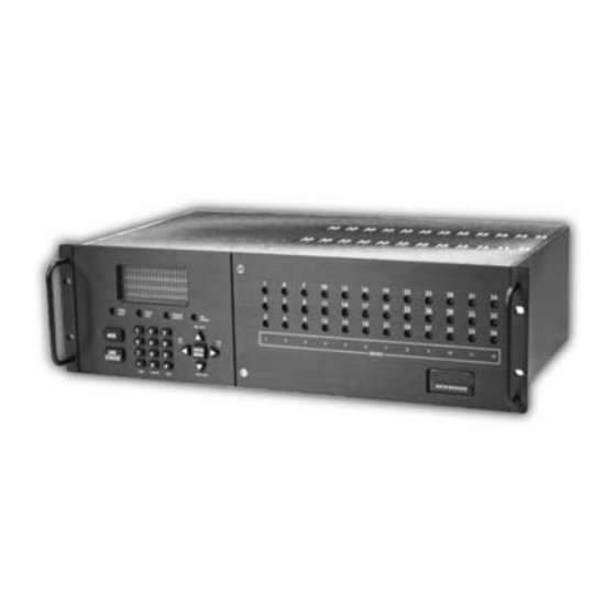
MX8000-3EX Installation and Operation Guide Overview The MX8000–3EX is assembled at the factory. One MX8000-LC3 tri-line card is shipped with the MX8000– 3EX receiver. Follow the procedures described in Section 3.7 to install additional line cards. SYSTEM SYSTEM OPERATOR CALL POWER FAULT LOGGED IN... -
Page 23: Rack Mounting
Section 3 – Installation Rack Mounting This diagram shows how to mount the MX8000–3EX in a rack enclosure. Model MX8000-3EX SYSTEM SYSTEM OPERATOR CALL POWER FAULT LOGGED IN PENDING Receiver PREV EVENT PREV NEXT CALL CALL DEVICE ENTER MENU STATUS Receiver NEXT EVENT HOME... -
Page 24: Hot Swapping Of Line Cards
MX8000-3EX Installation and Operation Guide Power/Non-power limited and High/Low Voltage Wiring must be separated by 1/4 inch spacing 120 VAC ± 10% Model MX8000-3EX 240 VAC ± 10% 50-60 Hz FUSE 100 VA 2.5A SLOW BLOW WARNING! This device has been verified to comply with FCC Rules Part 15. REPLACE ONLY HIGH VOLTAGE PRESENT WITH A FUSE... -
Page 25: Line Card Installation
Section 3 – Installation 5. From the front side of the receiver pull the line card straight back. This will pull the card free from the connector. A message similar to the following will be printed on the MX8000–3EX printer. 05/21/2004 11:42:53AM System Receiver #: 1 Reference #: 772 Expander Trouble #7... -
Page 26: Removing Line Cards
MX8000-3EX Installation and Operation Guide Top of Line Card Rear of Card Front of Card Line Card Insert From Line 2 Model MX8000-LC3 Display LEDs Front of MX8000 In This Direction Phone Line Connectors (Power Limited and Supervised) Figure 3–7: Line Card Position and Components 5. -
Page 27: Telephone Line Connection
Section 3 – Installation Telephone Line Connection See Figure 3–6 for the location of the phone line inputs. Connections to the MX8000–3EX phone jacks are made with a standard 7-foot phone cord. Use the following procedure to connect phone lines to the MX8000–LC3 line cards: 1. -
Page 28: 3.10.1 Printer Cable Pin-Outs
MX8000-3EX Installation and Operation Guide 3.10.1 Printer Cable Pin-Outs 25 pin printer cables are standard items at most electronic stores; however, if you create your own cable, use the pin description in Table 3–1. Table 3–1: External Printer Cable Pin Description MX8000–3EX Pin # Signal Direction... -
Page 29: 3.10.3 Remote Alert Output
Section 3 – Installation 3.10.3 Remote Alert Output 1. Plug the Battery/Relay wiring harness onto the connector on the back of the MX8000–3EX receiver. (See Figure 3–10.) Note: The remote alert output is a form C relay with a normally open or a normally closed wire. 2. -
Page 30: 3.13 Automation Computer Connection
MX8000-3EX Installation and Operation Guide 115 VAC ± 10% 240 VAC ± 10% 50-60 Hz FUSE 100 VA T630mAL 250 VAC WARNING! REPLACE ONLY HIGH VOLTAGE PRESENT WITH A FUSE DISCONNECT AC LINE AND OF SAME TYPE ALL OTHER CONNECTORS PROIR TO SERVICING RELAY RATING 2.5A 48VAC/VDC... -
Page 31: 3.13.1 Computer Port Baud Rate Selection
Section 3 – Installation MX8000 9-PIN DTE 9-PIN DTE 4 DTR DTR 4 DSR 6 6 DSR RTS 7 7 RTS CTS 8 8 CTS DCD 1 1 DCD TXD 3 3 TXD RXD 2 2 RXD GND 5 5 GND Figure 3–13: 9-Pin Null Modem Cable Connection 3.13.1 Computer Port Baud Rate Selection The computer port baud rate is selectable from 110 to 38400 (See Section 5 –... -
Page 32: Figure 3-14: Mx8000-3Ex Master/Slave Receiver Linking Cabling Connections
MX8000-3EX Installation and Operation Guide SLAVE SLAVE MASTER 115 VAC ± 10% 115 VAC ± 10% 115 VAC ± 10% PRINTER 240 VAC ± 10% 240 VAC ± 10% 240 VAC ± 10% 50-60 Hz 50-60 Hz 50-60 Hz FUSE FUSE FUSE 100 VA... - Page 33 Section 3 – Installation b. From the “Installer/Program Menu/General Options” display, select “1 Operation Mode” and configure for “Automatic.” From the “3 Communications” display, select “1 Port Functions” and configure COM1 for “Automation” and parallel port for “Auto Bkp Prn.” Note: If a serial printer is being used as a automation backup printer, configure COM2 as the “Auto Bkp Prn”...
- Page 34 MX8000-3EX Installation and Operation Guide 3–14...
-
Page 35: Section 4 Operation
Section 4 Operation This section covers information on how to operate the MX8000–3EX Receiver. Touchpad Function Buttons The front panel of the MX8000–3EX is made up of; a touchpad, containing numbers, arrows and buttons; a VFD display; and an array of LED indicators. (See Figure 4–1.) VFD Display SYSTEM SYSTEM... -
Page 36: Displays
MX8000-3EX Installation and Operation Guide Normal Programming Up Arrow Display previous item in the Call Go back to previous choice or History or System History. character. Down Arrow Display next item in the Call History Move to next choice or character. or System History. -
Page 37: Vfd Status Display
Section 4 – Operation Call Pending The acknowledge key No calls pending or all Calls pending. was pressed at least calls have been once, but not all the acknowledged. events in a call were acknowledged. Line Port LED The line card is (MX8000-LC3 operating normally. -
Page 38: Initial System Power Up
MX8000-3EX Installation and Operation Guide User Number User Area Number Area Initial System Power Up Apply power to the MX8000–3EX by plugging in the AC power cable. (See Figure 3–3.) When the MX8000– 3EX powers up, the display will go through the routine shown in Figure 4–4. Powerup Screen 123123C 11/13/00 Internal Keypad... -
Page 39: Default User Codes
Section 4 – Operation ✔ ✔ System Info ✔ ✔ Set Time & Date ✔ ✔ System Restart ✔ Printer Menu ✔ Program Menu ✔ Diagnostics Note: See Section 4.6 for detailed information on the main menu options. You must have at least one Installer Profile Code programmed in the system at all times. 4.4.3 Default User Codes At initial power up, the system provides two default user codes. -
Page 40: Modes Of Operation
MX8000-3EX Installation and Operation Guide ENTER 3. Press the button. MENU If the correct PIN is entered the VFD will display User Name Logged out . The “Operator Logged In” LED will also turn off. If an invalid code is entered the VFD will display Access code not verified. Modes of Operation This section describes the different modes of operation for the MX8000–3EX Receiver (normal mode and programming mode) and the options available in them. -
Page 41: How To Display The Main Menu
Section 4 – Operation 4.6.1 How to Display the Main Menu Once a user has logged on to the system (see Section 4.4.4), follow these steps to view the main menu options: ENTER 1. Press the button. MENU The VFD display will show the main menu options.... -
Page 42: Call History
MX8000-3EX Installation and Operation Guide Menu Controls ENTER To accept a menu item press MENU Or press Or press the number key Number can also corresponding be used to enter to the desired numeric information menu option where needed To Choose the next menu item press Go back to previous choice... -
Page 43: System History
Section 4 – Operation 4.6.4 System History System history displays any eventsthat are stored in the history buffer. 2=System History System events are any events related 3 System Info ¯ to the receiver operation such as line Event Number 4 Set Time &... -
Page 44: System Restart
MX8000-3EX Installation and Operation Guide Set Time and Date 1. Press the Menu button. 2. Press the 4 button. 3. Set the Hour (1 to 12). Time: 12:00AM 7. Set the Day. Time: 12:00AM The field to be Date: 01/01/01 Date: 01/01/01 The field to be changed flashes. -
Page 45: Printer Menu
Section 4 – Operation ENTER 5. Press . Users with an operator profile are done at this point. MENU The display reads Do you wish to set to factory default settings? Note: This display will only appear if the logged on User has an Installer Profile (see section 4.4.1). 6. -
Page 46: Figure 4-13: Print Report Menu Items
MX8000-3EX Installation and Operation Guide Table 4–6: Printer Menu Choices (cont’d) Printer Menu Choice 1 Choice 2 Comments Date/Time Y or N Indicates that this item will print on a report. Format Type Y or N Indicates that this item will not print on a Ref Number Y or N report. -
Page 47: Figure 4-15: System Configuration Print Items
Section 4 – Operation ENTER 2. Press the button to view the main menu items. MENU 3. Press for the printer menu. (See Figure 4–12.) 4. Press for print report menu. (See Figure 4–13.) 5. Press to print the system history. 6. -
Page 48: Table 4-7: Event Format Choices And Meaning
MX8000-3EX Installation and Operation Guide How to Print Line Card Statistics Follow these steps to print line card statistics: 1. Log on to the receiver (see Section 4.4.4 for log on procedure). ENTER 2. Press the button to view the main menu items. MENU 3. -
Page 49: Configure Printer
Section 4 – Operation EXAMPLE OF THE EVENT PRINTOUT For this example example, a yes answer was entered in the event format options for Date/Time, Format Type, Reference Number, Call Separator, and Device Number. Example of Print in Normal Mode 05/25/2004 02:53:37PM Device #: 1-34 Format #: 50 Reference #: 62 Account #: 1000... -
Page 50: Program Menu
MX8000-3EX Installation and Operation Guide 9. Enter the desired time (from 01-99 seconds). ENTER 10. Press MENU 11. Press to exit menu. 4.6.9 Program Menu If program is selected from the main menu thesystem will enter into “Program Mode”. (See Section 1=General Options 2 Line Device Menu 4.5 for information on modes of operation.) In... -
Page 51: Figure 4-19: Message Queue Level
Section 4 – Operation 4.6.10.2 Message Que Message Que gives a visual indication of how full the message queue is. It does this with 2=Message Que 3 Event Log both a percentage indication and a bar graph ¯ 4 Format-Raw Hex (made of *’s). -
Page 52: Figure 4-23: Line Statistics Display
MX8000-3EX Installation and Operation Guide 4.6.10.6 LC (Line Card) Statistics LC (Line) statistics allows you to view the call statistics of a specific Line in comparison to the total number of calls -
Page 53: Listen-In And Hang Up
Section 4 – Operation Table 4–9: Abbreviation Display Character Meanings/High Low Status ↑ ↑ ↑ ↑ (Bit High) ↓ ↓ ↓ ↓ (Bit Low) Abbreviated Character Meaning Serial Port (Com 1 & Com 2) Data Set Ready Ready Not Ready Data Terminal Ready Ready Not Ready... -
Page 54: Pbx Operation
MX8000-3EX Installation and Operation Guide 5 Listen-In Ring 2 Listen-In Tip 1 Manual Answer 6 Manual Answer Phone Line Connectors Figure 4–26: Phone Connector Pin-Out and Listen-in Wiring Diagram 4.7.2 PBX Operation Prior to performing listen-in functions on a PBX phone line system the receiver must be set up with the proper listen-in mode and PBX string. -
Page 55: Section 5 Programming
Section 5 Programming This section lists the programmable features in programming mode and the procedures for each of them. The options available are general options, line card options, and user options. NOTE After you complete your programming of the receiver, it is recommended that you make a printout of the programmed values for reference. -
Page 56: Programming Choices
MX8000-3EX Installation and Operation Guide Menu Controls ENTER To accept a menu item, press MENU Or press Or press the number key corresponding Number can also be used to enter to the desired menu option numeric information where needed To Choose the next menu item, press Go back to the previous choice Exit current menu or menu item. -
Page 57: Table 5-2: General Options Items And Description
Section 5 – Programming Table 5–2: General Options Items and Description The below table is organized into the order that menu items are displayed when General Options has been selected from the Program Menu. The first column reflects the first menu displayed, followed by the subsequent menu displays based on the item selected. - Page 58 MX8000-3EX Installation and Operation Guide Table 5–2: General Options Items and Description (cont’d) General Options Level 1 Choices Level 2 Choices Level 3 Choices Comments Items Packed (default) Each data packet to the automation computer contains multiple events. SK9000 Unpacked Each data packet to the automation computer contains a single event.
- Page 59 Section 5 – Programming Table 5–2: General Options Items and Description (cont’d) General Options Level 1 Choices Level 2 Choices Level 3 Choices Comments Items Term = 013, Head = Only visible if ADEMCO 685, FBII220, 010, ACK = 006, or CAPS ONLY format is selected.
-
Page 60: Operation Mode
MX8000-3EX Installation and Operation Guide Table 5–2: General Options Items and Description (cont’d) General Options Level 1 Choices Level 2 Choices Level 3 Choices Comments Items If this is selected an indicator will be sent to the automation computer that Strip Bad indicates a bad data block was Bad Data Blocks... -
Page 61: Display Options
Section 5 – Programming 5.3.1.1 How to change the operation mode Follow these steps to change the operation mode of the receiver: 1. Log on to the receiver. (See Section 4.4.4 for log on procedure.) ENTER 2. Press button. MENU 3. -
Page 62: How To Change Language Display
MX8000-3EX Installation and Operation Guide Table 5–4: Display Options and Descriptions (cont’d) Display Menu Choices Default Comments Items Attempts See Section 5.3.2.5 for step-by-step instructions. CPU Time ITI (Edit Options) CPU Type Panel Rev Arming Level FSK1 English If “English” is selected then the printer and VFD output for calls of these formats will be text descriptions. - Page 63 Section 5 – Programming 5.3.2.2 How to Change Time Format Display 1. Enter program mode. (See Section 5.1.) 2. Press for general options. 3. Press for display options. 4. Press until the display flashes on the time format field. 5. Press the button until the display flashes on the desired setting.
- Page 64 MX8000-3EX Installation and Operation Guide 10. Press the button until the display flashes on the desired month for daylight savings time to take effect. 11. Press to advance to the start week field. 12. Press the button until the display flashes on the desired week for daylight savings time to take effect.
- Page 65 Section 5 – Programming ENTER 7. Press to change the setting of that option. MENU Note: Additional presses of the enter button will toggle the setting between Yes and No. 8. Repeat steps 6 and 7 for any other ITI display options you wish to edit. 5.3.2.6 How to Edit Format Options To set these display options follow these steps:...
-
Page 66: Communications
MX8000-3EX Installation and Operation Guide 4. Press until the display flashes on the bright field. 5. Press the button until the display flashes on the desired setting. ENTER 6. Press MENU 5.3.3 Communications In the communication option the installer can configure the... - Page 67 Section 5 – Programming Table 5–5: Communications Options and Description (cont’d) Communications Choices Options Default Comments Menu ✔ 38400 19200 9600 7200 4800 Baud 2400 1200 D (# Data Bits) ✔ Com Port 1 ✔ S (# Stop Bits) Even P (Parity) ✔...
- Page 68 MX8000-3EX Installation and Operation Guide Table 5–5: Communications Options and Description (cont’d) Communications Choices Options Default Comments Menu Ack Timeout 1-120 seconds 4 sec See Section 5.3.3.5 for programming steps. Term=013 Only visible if ADEMCO 685, FBII220 or CAPS ONLY Head=010 format is selected.
- Page 69 Section 5 – Programming Table 5–5: Communications Options and Description (cont’d) Communications Choices Options Default Comments Menu ✔ Yes = will annunciate if an event, trouble or fault Printer condition occurs. ✔ No = no annunciation if an event, trouble or fault Bkp Printer condition occurs.
-
Page 70: Table 5-6: Initialization String Characters
MX8000-3EX Installation and Operation Guide 5. Press the button until the display flashes on the desired port setting. ENTER 6. Press MENU Note: See “How to Edit Init String (Com 1, Com 2, and Parallel Port)” in Section 5.3.3.4. 7. Repeat steps 5 through 6 until all parameters are set. 8. -
Page 71: How To Set Automation Communication
Section 5 – Programming Character Description Numeric characters, which can be entered from the touchpad or up/down arrows. a-z and A-Z Alpha characters entered with the up/down arrows. Special Characters entered with the up/down arrows. : _ - . , & * # ? C and space bar. - Page 72 MX8000-3EX Installation and Operation Guide Note: This feature should be disabled if the automation software package that you are using does not recognize Hex data. Follow these steps to enable or disable hex mode: 1. Enter program mode. (See Section 5.1.) 2.
-
Page 73: Table 5-7: Iti Automation Format Options
Section 5 – Programming 5. Press until the time field is flashing. 6. From the number keypad enter the desired number or press the button until the display flashes on the desired setting. ENTER 7. Press MENU 8. If you wish to exit, press until you exit this menu. - Page 74 MX8000-3EX Installation and Operation Guide N (No) Y (Yes) Extended panel Identification code. See 8.9.2.2. N (No) SupCh Supervisory Character is sent from the automation computer. The receiver will respond with an OKAY or supervisory record. See Sections 8.9.5 and 8.10.5. No Data Identifies the no data character in the log record.
-
Page 75: Table 5-8: On-Board Annunciator And Auxiliary Relay Options
Section 5 – Programming 5. Press the button to move through the annunciator output options. ENTER 6. When the equal sign highlights the option you wish to change, press MENU Note: Additional presses of the enter button toggle the setting between “yes” or “no”. See Table 5–8. 7. -
Page 76: System Options
MX8000-3EX Installation and Operation Guide 5.3.4 System Options In system options you can configure the backup battery configuration, the receiver ID number, and the normal state 4=System Options 5 Msg Queue Opt. of the auxiliary relay. ¯ 6 Slave List No Batt Bkp Single Rcvr ID=01 Strip Bad... -
Page 77: Table 5-10: 685, Caps, And Cp-220 1-9/A-Z Entries
Section 5 – Programming 5.3.4.2 How to Set the Receiver as a Single, Slave, or Master In large central stations, it may be desired to set up receivers in a master/slave relationship for reporting to a printer. To set the receiver to act as a single receiver, master receiver, or slave receiver, proceed as follows: 1. - Page 78 MX8000-3EX Installation and Operation Guide 5.3.4.4 How to Configure Output for Bad Data Blocks This feature selects how bad data blocks will be sent from the receiver to the automation computer. If Strip Bad is selected then an indicator will be sent to the automation computer when a bad data block is received, but the actual bad data block will not be sent.
-
Page 79: Message Queue Options
Section 5 – Programming 5. Press the button until the display flashes on the desired setting. ENTER 6. Press MENU To Exit: Press until you return to the main menu. 5.3.5 Message Queue Options Set the percentage of how full the message queue must... -
Page 80: Slave List
MX8000-3EX Installation and Operation Guide 5.3.5.3 Set the Event Release Time Used to define the maximum amount of time (in seconds) that the receiver will hold an event in memory prior to sending it to automation, VFD, and printer. The time begins at the beginning of the call or on an acknowledgement. -
Page 81: Virtual Receiver/Line Numbers
Section 5 – Programming 5.3.6.2 View Slave To view a slave to a master receiver: 1. Enter program mode. (See Section 5.1.) 2. Press for general options. 3. Press for slave list options. 4. Press to select view slave. 5. The receiver will display a listing of slave receivers assigned. To Exit: Press until you return to the main menu. -
Page 82: Line Device Menu
MX8000-3EX Installation and Operation Guide Notes: • If virtual receiver/line numbers are being used, DO NOT assign a hunt group number to a line. If a hunt group number is assigned, it takes precedence and the virtual number will not be used. •... -
Page 83: Table 5-11: Line Device Menu Options
Section 5 – Programming Table 5–11: Line Device Menu Options Select Line Device Device Type Menu Choice Choice Choice Choice Default Comments Defaults Enter Device Device # Copy Existing See the The order in which the corresponding Line will output numbers different handshakes. - Page 84 MX8000-3EX Installation and Operation Guide Table 5–11: Line Device Menu Options (cont’d) Select Line Device Device Type Menu Choice Choice Choice Choice Default Comments This feature selects the time period Inter-digit 0 or 1 ms to 2 between data blocks. Tm (ms) Sec.
- Page 85 Section 5 – Programming Table 5–11: Line Device Menu Options (cont’d) Select Line Device Device Type Menu Choice Choice Choice Choice Default Comments ✔ Caller ID to Caller ID Automation: When enabled, Caller ID information is output to the automation system only in the event that no alarm data is received from a...
- Page 86 MX8000-3EX Installation and Operation Guide Table 5–11: Line Device Menu Options (cont’d) Select Line Device Device Type Menu Choice Choice Choice Choice Default Comments In High Speed, messages with event codes of B, C, E, and BFSK Auto F are translated to ADEMCO High Speed messages.
-
Page 87: Add Line Device
Section 5 – Programming Table 5–11: Line Device Menu Options (cont’d) Select Line Device Device Type Menu Choice Choice Choice Choice Default Comments Used to set Caller ID Norm, Pream, detection methods, CID Monitor DTMF, or Norm gain, and impedance. Marks See Section 5.4.2.7 –6, –2, 0, 2,... -
Page 88: Edit Line - Mx8000-Lc3 (3 Line)
MX8000-3EX Installation and Operation Guide 5.4.2 Edit Line – MX8000–LC3 (3 Line) To edit an existing Line, follow these steps: 1. Log on to the receiver. (See Section 4.4.4 for log on procedure.) ENTER 2. Press button. MENU 3. Press for program menu. -
Page 89: Figure 5-14: Mx8000-Lc3 Handshake Order Number
Section 5 – Programming 2. Press for handshake sequence menu. Hs=1 Gr=1400_2225–2 Dur=0100 When display flashes on the Hs# (see Figure 5–13). Wait=1250 AckDur=08003. Press the button to change the ordered handshake number. Figure 5–14: MX8000–LC3 Handshake Order 1 = the first handshake tone sent 2 = the second Number... - Page 90 MX8000-3EX Installation and Operation Guide ENTER 5. When the desired wait time is flashing press MENU To Change the Acknowledgment Tone Duration Time: The acknowledgment tone duration time is the amount of time the receiver will send an acknowledgment tone to the reporting panel. See Table 5–11 for valid entries. 1.
-
Page 91: Figure 5-15: Mx8000-Lc3 Line Options Menu
Section 5 – Programming ENTER 5. When the desired wait time is flashing press MENU Set for 2300 and 1400 formats that require Acknowledgements on Even Rounds: 1. Follow the procedures in Section 5.4.2. 2. Press for pulse format menu. 3. - Page 92 MX8000-3EX Installation and Operation Guide To Change the Number of Rings, Follow These Steps: This controls the number of rings the line device needs to see before it will answer the call. 1. Follow the procedures in Section 5.4.2. 2. Press for Line Options menu.
-
Page 93: Figure 5-16: Mx8000-Lc3 Listen Mode Menu Display
Section 5 – Programming 2. Press for Line Options menu. 3. Press until the display flashes on the Sample field. 4. Enter the desired value from the keypad or press the button to change the line sample rate. Values range from 00 to 90 in 1 second increments (0=Line monitor disabled, 1=1 second, 2=2 seconds, 3=3 seconds and so on). -
Page 94: Table 5-13: Valid Programmable String Characters
MX8000-3EX Installation and Operation Guide Table 5–13: Valid Programmable String Characters Character Description Flash hook. Delay 500ms Delay 2 seconds Force a hang up of the line. Detect dial tone. Check to see if the line is busy by looking for a busy tone. 0-9, *, #, A, B, C, D DTMF digits. -
Page 95: Table 5-14: Account Characters
Section 5 – Programming Figure 5–17 shows the next display. Mode=Not Used Timeout=000 ENTER To Add a Listen-In Account MENUNote: Panels that send listen-in commands (Contact ID E606 or SIA LF and LE) as part of their message do not need their account number in an account list. -
Page 96: Figure 5-18: Mx8000-Lc3 Miscellaneous Phone Line Options
MX8000-3EX Installation and Operation Guide ENTER 5. Press MENU 5.4.2.5 Misc. Line Opt. Some phone lines may use echo suppression, a billing delay feature, a hunt group or you may need to set 5 Misc. Line Opt. various ring options. -
Page 97: Figure 5-19: Mx8000-Lc3 Ring Options
Section 5 – Programming 3. Press until the display flashes on the BillDly field. 4. Press the button to toggle the billing delay between “Yes” or “No”. ENTER 5. When the desired setting is flashing press MENU To Change the Hunt Group: Note: If a Hunt Group number is assigned to a line that has a virtual line number assigned, the Hunt Group Number will take precedence and the virtual line and receiver numbers will be ignored. - Page 98 MX8000-3EX Installation and Operation Guide Minimum Ringer Off Time is used to determine what the minimum interval is between rings so that the system will treat two burst separated by a brief pause as one ring. RErr (Ringer Off Error) – To determine when a new call is received, the system will add the value of ROff, Min, and this value.
-
Page 99: Figure 5-20: Mx8000-Lc3 Ademco Auto Output Options
Section 5 – Programming 3. Press until the display flashes on the HngUp field. 4. Enter the desired value from the keypad or press the button to change the number of seconds. ENTER 5. When the desired number of seconds is flashing press MENU 6. - Page 100 MX8000-3EX Installation and Operation Guide 4. Press the button to change the option from HiSpeed to Normal or vice versa. ENTER 5. When the desired setting is flashing press MENU 6. To exit press How to Set FBII Out 1. Follow the procedures in Section 5.4.2. 2.
-
Page 101: Figure 5-21: Mx8000-Lc3 Line Gain Options
Section 5 – Programming 5.4.2.7 Line Gain Opt. This selection is used to select the gain for transmit andreceive for a line. 7 Line Gain Opt. How to Set Transmit Gain < Exit Menu 1. Follow the procedures in Section 5.4.2. 2. - Page 102 MX8000-3EX Installation and Operation Guide 6. To exit press How to Set CID Gain Caller ID gain sets the gain of the Caller ID receive logic. Note: This option is will only be applicable when Caller ID has been selected. 1.
-
Page 103: Copy Device(S)
Section 5 – Programming 4. Press the button to change the Ringer Impedance. ENTER 5. When the desired setting is flashing press MENU 6. To exit press 5.4.3 Copy Device(s) Copy Device(s) allows you to either program a line to defaults or copy the programming of an existing line. 5.4.3.1 To Program the Default Settings Into a Device 1. -
Page 104: Clear Device
MX8000-3EX Installation and Operation Guide 7. Press the button until the equal sign highlights the desired Source Device number. ENTER 8. Press MENU 9. Press the button until the equal sign highlights the desired Target Device number. ENTER 10. Press the button to toggle between Y (yes) and N (no). -
Page 105: User List
Section 5 – Programming 3. Press (MX8000–LC3) to select your line card type. 4. Press to view Devices. 5. When display shows the list of Devices (see Figure 5–22) press the to scroll through the list of Devices. 6. To exit press User List User List is used to program and store the information on the... -
Page 106: Editing A User
MX8000-3EX Installation and Operation Guide 5. Press to add a user. The user number to be programmed will appear in the display for one second. This user number will always be the lowest available user number. 6. Press the arrow buttons to move through the available characters. Table 5–16: Available Characters Characters Comments... -
Page 107: Clearing A User Out Of The Receiver
Section 5 – Programming ENTER 7. When the equal sign highlights the user you wish to edit press MENU ENTER 8. If you do not want the user name changed, press MENU To change the user name, press the arrow buttons to move through the available characters. - Page 108 MX8000-3EX Installation and Operation Guide 5–54...
-
Page 109: Section 6 Compatible Reporting Formats
Section 6 Compatible Reporting Formats This section lists all the reporting formats that are compatible with the MX8000–3EX receiver. Table 6–1 shows the formats that the MX8000–3EX receiver can decode and handshake frequency format group that accommodates that format (see Section 5.3.6 for line card programming). Each line card can decode every format listed below;... - Page 110 MX8000-3EX Installation and Operation Guide (cont’d) Table 6–1: Formats compatible with the MX8000–3EX Communication Handshake Format Name Description Group Format Group SX-III, SX-IVA Sends a 5-digit account code in a Bell 103 format 2225 Hz with checksum. The data is decoded into English SX-IVB account information.
-
Page 111: Format Numbers Used In Printer Output
Section 5 – Programming Format Numbers Used In Printer Output In a printed report the format used by a calling panel is listed as a number, that number represents a particular format. Table 6–2 lists these numbers along with the corresponding format. Table 6–2: Formats By Report Number Format Format... - Page 112 MX8000-3EX Installation and Operation Guide Important! Due to the increasing number of formats a single line can accept and the wide variety of manufacturer’s specifications for handshake/acknowledgement tones required for their digital dialers to communicate, we strongly recommend observing the following rules for handshake tone order.
-
Page 113: Section 7 Troubleshooting
Section 7 Troubleshooting This section contains a list of possible error messages and a troubleshooting process for each. Error Messages Table 7–1 lists the error messages that are displayed on the VFD of the receiver as well as the message sent to the printer. - Page 114 MX8000-3EX Installation and Operation Guide Table 7–1: Error Messages (cont’d) VFD Messages Printer Message Description What to Do Error Error ✔ Expander Expander Trouble Trouble with a device connected to the Trouble SBUS. ✔ Expander Trbl Expander Trouble The trouble condition of a SBUS device was Restore corrected.
- Page 115 Section 7 – Troubleshooting Table 7–1: Error Messages (cont’d) VFD Messages Printer Message Description What to Do Error Error ✔ Bkup Computer Bkup Computer A communication problem exists between Check cable Trbl Trouble the backup automation software and the connections. Verify receiver.
-
Page 116: Unrecognized Reports
MX8000-3EX Installation and Operation Guide Table 7–1: Error Messages (cont’d) VFD Messages Printer Message Description What to Do Error Error ✔ Line Fault Line Fault Restore Phone line voltage has been restored to Restore normal parameters. ✔ LinePort LinePort Record A line card has been deleted. -
Page 117: Removing The Cpu, Ps, User Interface Assembly
Removing the CPU, PS, User Interface Assembly Once Technical Support has determined that a problem exists with either the CPU, Power Supply, or the User Interface, use the following procedure to remove the assembly and return it to Honeywell for repair. 1. Disconnect AC power Cable. - Page 118 MX8000-3EX Installation and Operation Guide ✶ ✶ ✶ ✶ 3. Press the button, then the button. STATUS Safe Mode Activated The display will read ENTER 4. Press MENU 5. Enter the default Installer code or 8000. 7–6...
-
Page 119: Section 8 Automation Communication Formats
Section 8 Automation Communication Formats Introduction The receiver supports several automation communication formats that are used to communicate with an automation computer. The supported formats are Silent Knight’s proprietary protocol. The ADEMCO protocol is described in Section 8.2. !WARNING! • If you are receiving Contact ID ® 10 format on your MX8000–3EX receiver, your automation software must be compatible with 10-digit account numbers, you must not use SK9000, ITI Generic, or ITI Enhanced automation protocols. -
Page 120: Reporting Formats And Automation Protocol Support
MX8000-3EX Installation and Operation Guide Reporting Formats and Automation Protocol Support Table 8–2 provides a listing of the reporting formats supported by each type of automation protocol in the MX8000–3EX. Table 8–2: Reporting Formats and Automation Protocol Support Automation Protocol Reporting Format ADEMCO ADEMCO... -
Page 121: Ademco 8000
Section 8 – Automation Communication Formats ADEMCO 8000 Because of the additional features and program capabilities of the MX8000–3EX receiver over its predecessor the 9000 receiver, it was necessary to develop a new automation protocol. ADEMCO 8000 protocol addresses these needs. The following sections describes the three different types of data blocks (system message, heart beat message, and call message) that the ADEMCO 8000 will send to the automation computer, and the components of these data blocks. -
Page 122: Table 8-5: Dialer Format Types By Code
MX8000-3EX Installation and Operation Guide 8.4.2.1 Dialer Format The ADEMCO 8000 format takes advantage of additional format numbers and outputs information with greater detail about the dialer format. Table 8–5 lists the dialer format code and indicates the type of dialer associated with that number. Table 8–5: Dialer Format Types By Code Code Dialer Type... -
Page 123: Table 8-7: Call Message Components
Section 8 – Automation Communication Formats Note: Caller ID to Automation – When enabled, Caller ID information is output to the automation system only in the event that no alarm data is received from a security system control panel. Example: <$26><“051697”><$22><“081356”><$22><“01”><$22><“0001”><$22><“004”><“01”> <12h><“1-800-328-0103”><11h><“ADEMCO”><$05><“123456”><$22><“BA01”>... -
Page 124: Table 8-8: Call Message With Listen-In Data
MX8000-3EX Installation and Operation Guide The following is an example of a call message containing a listen-in indicator: Example:<$2A><“060”> <$0D> Table 8–8 describes the components of a call message containing a listen-in indicator. Table 8–8: Call Message With Listen-in Data Character Description ... -
Page 125: System Message Block
Section 8 – Automation Communication Formats Table 8–9: Bad Data Field Indicator Components Character Description <$23> Bad data indicatorBad data ASCII hex data dump. <$23> Bad data indicator Bad data ASCII hex data dump. <$05> Account number field indicator <“123456”>... -
Page 126: Heart Beat Message Block
MX8000-3EX Installation and Operation Guide Table 8–11: System Messages System Message Description Hex Code to ASCII Character <$41><2 ASCII Byte LC #> Common Listen-in Begin, followed by the line card number. <$41> = A <$42><2 ASCII Byte LC #> Common Listen-in End, followed by the line card number. <$42>... -
Page 127: Validation Byte (V-Byte)
Section 8 – Automation Communication Formats Table 8–12 lists the components shown in the above example and gives a description for each of them. Table 8–12: Link Test Components Component Description <$03> Message type identifier. <“051997”> Date information, consisting of six ASCII bytes. <$22>... -
Page 128: Table 8-13: Response Messages By The Mx8000-3Ex Receiver
MX8000-3EX Installation and Operation Guide Table 8–13: Response Messages by the MX8000–3EX Receiver ASCII Hex Character Name Description Character The request is granted. NACK The request is unrecognized because of one of the following reasons: • Checksum error • Invalid request code/format ESC (Escape) The request is refused because of one of the following:... -
Page 129: Table 8-16: Log-Off Request Components
Section 8 – Automation Communication Formats Table 8–16: Log-off Request Components Component Description <$4B> Command request identifier. See Table 8–14.Receiver ID number. 1 or 2 ASCII digits. <$22> Separator The user’s PIN code. Validation Byte (V-byte). See 8.4.5. <$0D>... -
Page 130: Table 8-20: Extend Listen-In Period Request Components
MX8000-3EX Installation and Operation Guide 8.4.7.4 Common Listen-in Extend/End Request During a listen-in operation if the call requires additional time you can extend the listen-in period by sending an extend request. At the end of a listen-in call you can end the session by sending an end request. Some control panels send a listen-in period included in the reported message to the receiver. -
Page 131: Link Test Request
Section 8 – Automation Communication Formats 8.4.7.6 Link Test Request The automation computer can send a link test request to the MX8000–3EX receiver to test the communication link between the receiver and the automation computer. The automation computer simply sends a <$0D> and the MX8000–3EX receiver will respond. ADEMCO 685 Automation Protocol 8.5.1 Low Speed 3x1, 4x1, and 4x1 Express Automation Protocols... -
Page 132: 685 Contact Id
MX8000-3EX Installation and Operation Guide LFRG 1234 NNNN NNNN NCR TERMINATOR (ASCII CARRIAGE RETURN - HEX 0D) CHANNEL REPORT CODE, CHANNEL 9 SPACE (ASCII SPACE CHARACTER - HEX 20) CHANNEL REPORT CODE, CHANNELS 5-8 SPACE (ASCII SPACE CHARACTER - HEX 20) CHANNEL REPORT CODE, CHANNELS 1-4 SPACE (ASCII SPACE CHARACTER - HEX 20) ACCOUNT NUMBER... -
Page 133: Table 8-23: Contact Id Event Definition Codes
Section 8 – Automation Communication Formats Table 8–23: Contact ID Event Definition Codes EVENT DATA TYPE ALARMS Medical Alarms -100 100 Medical Zone 101 Personal Emergency Zone 102 Fail to report in Zone Fire Alarms -110 110 Fire Zone 111 Smoke Zone 112 Combustion Zone... - Page 134 MX8000-3EX Installation and Operation Guide Table 8–23: Contact ID Event Definition Codes (continued) EVENT DATA TYPE 158 High temp Zone 159 Low temp Zone 161 Loss of air flow Zone 162 Carbon Monoxide detected Zone 163 Tank level Zone SUPERVISORY Fire Supervisory -200 and 210 200 Fire Supervisory Zone...
- Page 135 Section 8 – Automation Communication Formats Table 8–23: Contact ID Event Definition Codes (continued) EVENT DATA TYPE Communication Troubles -350 and 360 350 Communication trouble Zone 351 Telco 1 fault Zone 352 Telco 2 fault Zone 353 Long Range Radio xmitter fault Zone 354 Failure to communicate event Zone...
- Page 136 MX8000-3EX Installation and Operation Guide Table 8–23: Contact ID Event Definition Codes (continued) EVENT DATA TYPE 463 Re-arm after Alarm User 464 Auto-arm Time Extended User 465 Panic Alarm Reset Zone 466 Service On/Off Premises User Remote Access -410 411 Callback request made User 412 Successful download/access User...
- Page 137 Section 8 – Automation Communication Formats Table 8–23: Contact ID Event Definition Codes (continued) EVENT DATA TYPE 574 Group bypass User 575 Swinger bypass Zone 576 Access zone shunt Zone 577 Access point bypass Zone 578 Vault Bypass Zone 579 Vent Zone Bypass Zone TEST / MISC.
-
Page 138: Mx8000-3Ex/685 System Messages
MX8000-3EX Installation and Operation Guide Table 8–23: Contact ID Event Definition Codes (continued) EVENT DATA TYPE 913 Supervisory Point test Start/End User 914 Hold-up test Start/End User 915 Burg. Test Print Start/End 916 Supervisory Test Print Start/End 917 Burg. Diagnostics Start/End Zone 918 Fire Diagnostics Start/End Zone... -
Page 139: Table 8-24: Mx8000-3Ex/685 System Messages
Section 8 – Automation Communication Formats Table 8–24: MX8000–3EX/685 System Messages Printer Message 685 Automation Output MX8000–3EX INITIATED MESSAGES LC Line Fault Event LINE XXXX XXXX 7 (5 = normal, 1 new fault, 3 = line restore, 6 = previously reported) LC Line Fault Restore Event LINE XXXX XXXX 7 (5 = normal, 1 new fault, 3 = line restore, 6 =... -
Page 140: Fbii Cp-220 Automation Protocol
MX8000-3EX Installation and Operation Guide FBII CP-220 Automation Protocol 8.7.1 3x1, 4x1, and 4x2 Automation Protocols When the MX8000–3EX receives a 3x1, 4x1, and 4x2 transmission operating in the CP-220 mode, the output protocol to the computer is as shown in Figure 8–6. HRG123422T PROGRAMMABLE TERMINATOR EVENT CODE... -
Page 141: Cp-220/Silent Knight
Section 8 – Automation Communication Formats SPACE -ASCII (20HEX) LFRG 1234 18 QXYZ GG FCCC CR PROGRAMMABLE HEX TERMINATOR (USUALLY CARRIAGE RETURN) 3 DECIMAL DIGITS REPRESENTING CONTACT OR USER DEFINES CCC. C = CONTACT, U = USER. 2 DIGIT GROUP NUMBER EVENT DEFINITION CODE EVENT CHARACTER WHERE E = EVENT, NEW ALARM/OPENING... -
Page 142: Mx8000-3Ex/Cp-220 System Messages
MX8000-3EX Installation and Operation Guide A space will be sent as the zone digit any time that the MX8000–3EX receives a zero or letter a for the zone digit. FORMAT 6 When the MX8000–3EX receives a Silent Knight Format 6 (FSK 2) transmission, the output protocol to the computer is as shown in Figure 8–12. -
Page 143: Sk9000 Protocol
Section 8 – Automation Communication Formats SK9000 Protocol The following sections describe the computer protocol. 8.8.1 Data String Description And Special Characters Table 8–26: Data String Description Byte(s) Data Element Description Occupied Identifier The first byte of a message is the identifier. This byte is always $01 or $27. $01 = a system message $27 = a call from a panel Date... -
Page 144: Calls From Panels
MX8000-3EX Installation and Operation Guide 8.8.2 Calls From Panels The basic format of a message is shown in the example below. For a complete description of each data element, see Table 8–26. Indicates whether message is a call New Message Indicator from a panel or a system message. -
Page 145: Bad Data
Section 8 – Automation Communication Formats Message 1 $27 $30 $36 $32 $37 $39 $34 $22 $30 $33 $34 $35 $22 $35 $31 $05 $30 $32 $33 $34 < Event Data > $2C $XX $OD Separator Date Separator Time Account # Up To 51 Bytes More Data to Separator... -
Page 146: System Messages
MX8000-3EX Installation and Operation Guide 8.8.7 System Messages The character $01 at the beginning of a data string indicates that the MX8000–3EX is reporting its internal status. A sample system message is shown in Figure 8–15. Table 8–28 lists the possible system messages and what format the data can take. -
Page 147: Iti Generic Computer Format
Section 8 – Automation Communication Formats The MX8000–3EX ignores any other communication from the computer when it is awaiting ACKing or NACKing. Generally, after two NACKs or two timeout periods of no response from the computer, the MX8000–3EX generates a “computer trouble” message. •... -
Page 148: Table 8-31: Upper Nibble Description
MX8000-3EX Installation and Operation Guide 8.9.2.1 Control Panel Type and Zone Attribution Byte Byte 4 (see Table 8–30) of the report record is divided into upper and lower nibbles. The upper nibbles (4 most significant bits) contain the code indicating the panel type. Table 8–31: Upper Nibble Description Upper Nibble Description... -
Page 149: Log Record
Section 8 – Automation Communication Formats 8.9.2.3 Alarm Codes Table 8–34 lists the alarm codes used in byte 13 of the report record, and a description of the alarm codes. Table 8–34: Alarm Code and Description Alarm Codes Description Alarm Bypass Closing Report Dial out audio alarm... -
Page 150: Test Record
MX8000-3EX Installation and Operation Guide 8.9.4 Test Record A test record is sent when panel date/time is updated. The following is an example of a test record: <$0A><"IT IRCV 234A"><$0D> Table 8–36: Test Record Components and Description Character Description <$0A> Start of record (line feed). -
Page 151: 8.10.2 General Record Structure
Section 8 – Automation Communication Formats Table 8–38: Number and ITI Digit Equivalent Represented by Number ITI Digit 0 - 9 0 - 9 10 - 35 A - Z 36 - 61 a - z 8.10.2 General Record Structure Each record begins with <"|[">... -
Page 152: Table 8-41: Report Record Components And Description
MX8000-3EX Installation and Operation Guide Table 8–41: Report Record Components and Description Character Description <"|["> Start of record indicator. Report record identifier.Unit ID = A, followed by receiver ID = 1. <"|IA1"> <"|LB"> Line Card #, B = 11. Acceptable values are 0-9, A (= 10), B (=11), C (=12). Account Number. -
Page 153: Table 8-43: Panel Type Characters
Section 8 – Automation Communication Formats Table 8–42: Information Field Identifiers (cont’d) Field Identifier Description Acceptable Values Panel type and revision. One panel type code byte followed by a 4-digit revision number. See Table 8–43. Group and attribute information. Contact ITI for group and attribute information. -
Page 154: 8.10.4 Test Record
MX8000-3EX Installation and Operation Guide 8.10.3.3 Condition Codes Condition codes are a one-digit character that indicates the nature of the call from a control panel to the receiver. Table 8–44 lists the different condition codes and their descriptions: Table 8–44: Condition Codes and Descriptions Condition Code Description Alarm... -
Page 155: 8.10.5 Supervisory Record
Section 8 – Automation Communication Formats 8.10.5 Supervisory Record When the automation computer sends a supervisory character to the receiver, the receiver will answer with a supervisory record. A supervisory record (heartbeat) is sent periodically to the automation computer. How often the supervisory record is sent is set through programming (see Section 5.3.3.5 page 5–18). -
Page 156: 8.11 Us Ascii Character Code
MX8000-3EX Installation and Operation Guide Table 8–47: Checksum Verification Process Character ASCII Code Additive Checksum XOR Checksum 00 + 7C = 7C FF ^ 7C = 83 7C + 5B = D7 83 ^ 5B = D8 D7 + 58 = 12F D8 ^ 58 = 80 12F + 7C = 1AB 80 ^ 7C = FC... -
Page 157: Appendix A Programming Quick Chart
Appendix A Programming Quick Chart Table A–1: Programming Quick Chart Program Mode Choices Choices Choices Choices Comments Options Manual See Section 4.5 for description of modes of operation. See also Section 5.3.1. Operation Mode Automatic Log Only English See Section 5.3.2 for details. Language español Not available at this time. - Page 158 MX8000-3EX Installation and Operation Guide (cont’d) Table A–1: Programming Quick Chart Program Mode Choices Choices Choices Choices Comments Options 0 .. 9 PULSE 0 .. F Packed SK9000 Unpacked Format Config. (continued) Zero ACRON Space HISPEED Display Options Hispeed (continued) See Section 5.3.2.7.
- Page 159 Appendix A – Programming Quick Chart (cont’d) Table A–1: Programming Quick Chart Program Mode Choices Choices Choices Choices Comments Options CAPS, SK9000, ADEM See Section 5.3.3.5 for details. Format 8000, ADEM 685, FBII 220, ITI Gen, ITIComp Feature is only available if ADEM 8000 or Y (yes) SK9000 automation protocol is selected.
- Page 160 MX8000-3EX Installation and Operation Guide (cont’d) Table A–1: Programming Quick Chart Program Mode Choices Choices Choices Choices Comments Options No Battery Bkp Yes or No See Section 5.3.4.1 for details. Battery Backup Battery Bkp Yes or No See Section 5.3.4.1 for details. DC Bkp Yes or No No charging current.
- Page 161 Appendix A – Programming Quick Chart (cont’d) Table A–1: Programming Quick Chart Program Mode Choices Choices Choices Choices Choices Comments Options Use Defaults See Section 5.4.1 for details. Device # Device Copy Existing Handshake 1 through 6 See Section 5.4.2.1 for details. Sequence Format 1400_2300–2, 1400Hz,...
- Page 162 MX8000-3EX Installation and Operation Guide (cont’d) Table A–1: Programming Quick Chart Program Mode Choices Choices Choices Choices Choices Comments Options See Section 5.4.2.6 for details BFSK Auto HiSpeed or 4/2 3/1 Restore HiSpeed or 3/1 Ademco 4/2 Out Normal or HiSpeed Auto Opt S/Fast or LAR300 Pulse Extended...
-
Page 163: Appendix B Receiver Update Procedure
Appendix B Receiver Update Procedure A receiver update may be issued by when necessary. These updates are supplied either as a download from a web site or on floppy disk. !WARNING! • It is recommended that you make a printout of your programmed values for reprogramming after the update is complete. - Page 164 MX8000-3EX Installation and Operation Guide EDITING THE BAT FILE You must edit the “bat” file supplied with your upgrade software if you are not able to use the COM 1 port on your computer. To edit the bat file: 1. In Windows, load Notepad. 2.
-
Page 165: Appendix C Index
Appendix C Index Disable Line Device .............5–37, 5–38 240 VAC ................. 3–9 Display options ................5–7 3/1 Restore Out Edit Line Device MX8000-LC3..............5–45 MX8000-LC3 ..............5–34 4/2 Out Event Release ...............5–26 MX8000-LC3..............5–45 Extended Out Accessories................1–1 MX8000-LC3 ..............5–46 ACKing FBII Out ADEMCO 8000 .............. - Page 166 MX8000-3EX Installation and Operation Guide model number ................. 4–9 5–22 Receiver ID............4–9, , 5–23 NACKing Receiver Master..............5–23 ADEMCO 8000 ..............8–9 Receiver Single..............5–23 ITI Generic................ 8–32 Receiver Slave...............5–23 SK9000................8–28 Record Structure..............8–33 No Data Received ..............7–4 Report Record ...............8–33 Normal mode ................
- Page 167 For the latest warranty information, please go to: www.honeywell.com/security/hsc/resources/wa...
- Page 168 2 Corporate Center Drive, Suite 100 P.O. Box 9040, Melville, NY 11747 Copyright © 2010 Honeywell International Inc. www.honeywell.com/security ÊK5982-1=Š K5982-1 1/10 Rev. A...